sewerin COMBIPHON User manual
Operating
Instructions
COMBIPHON®
EDENBROS, LLC

Measurable success by Sewerin equipment
Congratulations. You have chosen a quality instrument manufactured
by Hermann Sewerin GmbH.
Our equipment will provide you with the highest standards of perfor-
mance, safety and efciency. They correspond with the national and
international guide-lines.
Please read and understand the following operating instructions before
using the equipment; they will help you to use the instrument quickly and
competently. If you have any queries we are available to offer advice
and assistance at any time.
Yours
Hermann Sewerin GmbH
Robert-Bosch-Straße 3
33334 Gütersloh, Germany
Tel.: +49 5241 934-0
Fax: +49 5241 934-444
www.sewerin.com
info@sewerin.com
EDENBROS, LLC
PO BOX 247
ST. JAMES, MO 65559
Phone: +1
800-526-5246
Fax:
+1 800-807-9368
www.
edenbros.com

Operating Instructions
11.10.2010 – V 1.X – 103411 – en
COMBIPHON®
For your safety
This product may only be operated by appropriately-trained persons who
are familiar with the relevant operating manual.
It may only be used for its designated purpose, i.e. for industrial and com-
mercial use.
Repair work may only be carried out by specialists or by persons who have
undergone appropriate training.
Any alterations or modications to the product require the prior approval of
Hermann Sewerin GmbH. In the event of unauthorised alterations to the
product the manufacturer accepts no liability for damage.
Only Hermann Sewerin GmbH accessories may be used with the product.
Only spare parts approved by us may be used for repairs.
Hermann Sewerin GmbH accepts no liability for damage resulting from
non-compliance with the foregoing. The guarantee and liability provisions
in the Hermann Sewerin GmbH terms of sale and supply are not extended
by the foregoing.
We reserve the right to make changes in the context of continued techni-
cal development.
In addition to these instructions, please comply with generally applicable
safety and accident-prevention regulations!
Symbols used:
CAUTION!
This symbol warns of dangers that may threaten
the safety of the user or maty damage or destroy
the product.
Note:
This symbol ags information and hints extending
beyond the actual operation of the product.

I
Contents Page
1 System overview .....................................................................1
2 Intended usage and principle of operation...........................3
3 COMBIPHON system ..............................................................5
3.1 Generator G5 ............................................................................6
3.2 Loading the Battery ...................................................................7
3.3 Generator G5 – Radio...............................................................7
3.4 AC/DC adapter L.......................................................................8
3.5 Car cable L................................................................................9
4 Knocker..................................................................................10
4.1 Knocker – Starting and operating ........................................... 11
4.2 Working with the Knocker........................................................ 11
4.3 Maintaining the Knocker..........................................................12
5 Stopper...................................................................................13
5.1 Stopper – Starting and operating ...........................................14
5.2 Working with the Stopper ........................................................15
5.3 Maintaining the Stopper ..........................................................16
5.4 Important notes on use and care ............................................18
6 Troubleshooting ....................................................................19
6.1 General ...................................................................................19
6.2 Knocker ...................................................................................19
6.3 Stopper....................................................................................20
7 Technical data........................................................................21
7.1 Generator G5 and G5 Radio ...................................................21
7.2 AC/DC adapter L.....................................................................21
7.3 Knocker ...................................................................................22
7.4 Stopper....................................................................................22
7.5 Radio remote control (Option).................................................22

II
Contents Page
8 Appendix................................................................................23
8.1 EC-Declaration of conformity ..................................................23
8.2 Advice on disposal ..................................................................23
8.3 Modication History - Software ...............................................24
9 Index.......................................................................................25
1
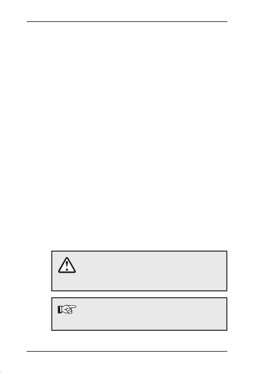
1 System overview
1 System overview
COMBIPHON system
1Foam insert for
accessories
1
4
2
3
6
78
5
2 AC/DC adapter L
3Car cable L
4 Knocker
5Remote control
6 Generator G5 with
control panel
7Connection for an
external power source
8Connection for
oscillator Picture 1: COMBIPHON system
9Stopper
10 Standpipe
Picture 2: Stopper and accessories
9
10

2
1 System overview
Generators G5 control panel
Knocker LED
COMBIPHON
G5
Stopper LED
Booster LED
ON/OFF switch /
Intensity adjuster*
Battery LED
Frequency LED
Frequency adjuster
(Knocker/Stopper)
Picture 3: Control panel
* Intensity adjuster for Knocker only. The intensity of the Stopper
is set via a valve.

3
2 Intended usage and principle of operation
2 Intended usage and principle of operation
Plastic pipes cannot be located using traditional electromagnetic
methods as they are not electrically conductive.
The acoustic method uses a different principle for locating pipes:
The pipes propagate mechanical oscillations better than the sur-
rounding earth. If the pipe is subject to the right oscillations, they
are transferred along the pipe and via the earth to the earth’s sur-
face. These oscillations can be detected according to the principle
of electro-acoustic leak detection by a ground microphone and
receiver equipped with headphones. The AQUAPHON System,
for example, is ideally suited for this task.
Picture 4: Acoustic leak detection
Similar to the acoustic detection of water leakages, the pipeline
is generally located where the highest intensity is detected. This
is how bre cement and metal pipes are principally detected.
The COMBIPHON system consists of the Generator G5 central
control unit, the AC/DC adapter L, a car cable L as well as vari-
ous oscillators (Knocker, Stopper).
The Knocker places the service pipes (water or gas) under oscil-
lation by knocking on the outside of the pipeline like an electric
hammer. Gas or air-lled pipes are sometimes difcult to detect
since the conductive water column is missing.

4
2 Intended usage and principle of operation
The Stopper creates a pressure wave by rapidly opening and clos-
ing the ow to the pipe. Main pipes (water) require more energy
to be placed under oscillation. The water column is set in motion
by extracting water from a hydrant. A special shut-off element
known as the Stopper slows down the motion of the water col-
umn at regular intervals. The resulting pressure waves propagate
along the pipeline and can be detected over long distances. The
intensity of the generated pressure wave can be adjusted via the
valve on the device.
5
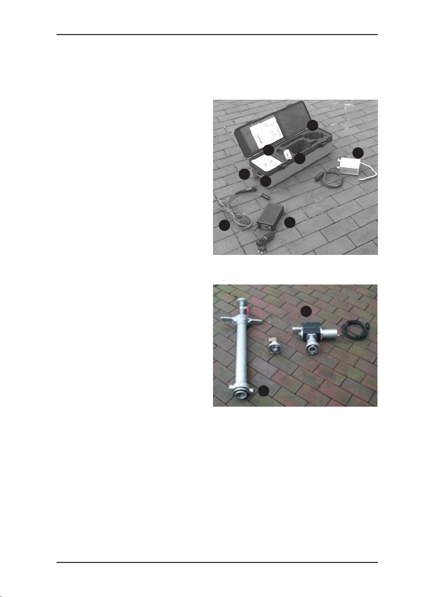
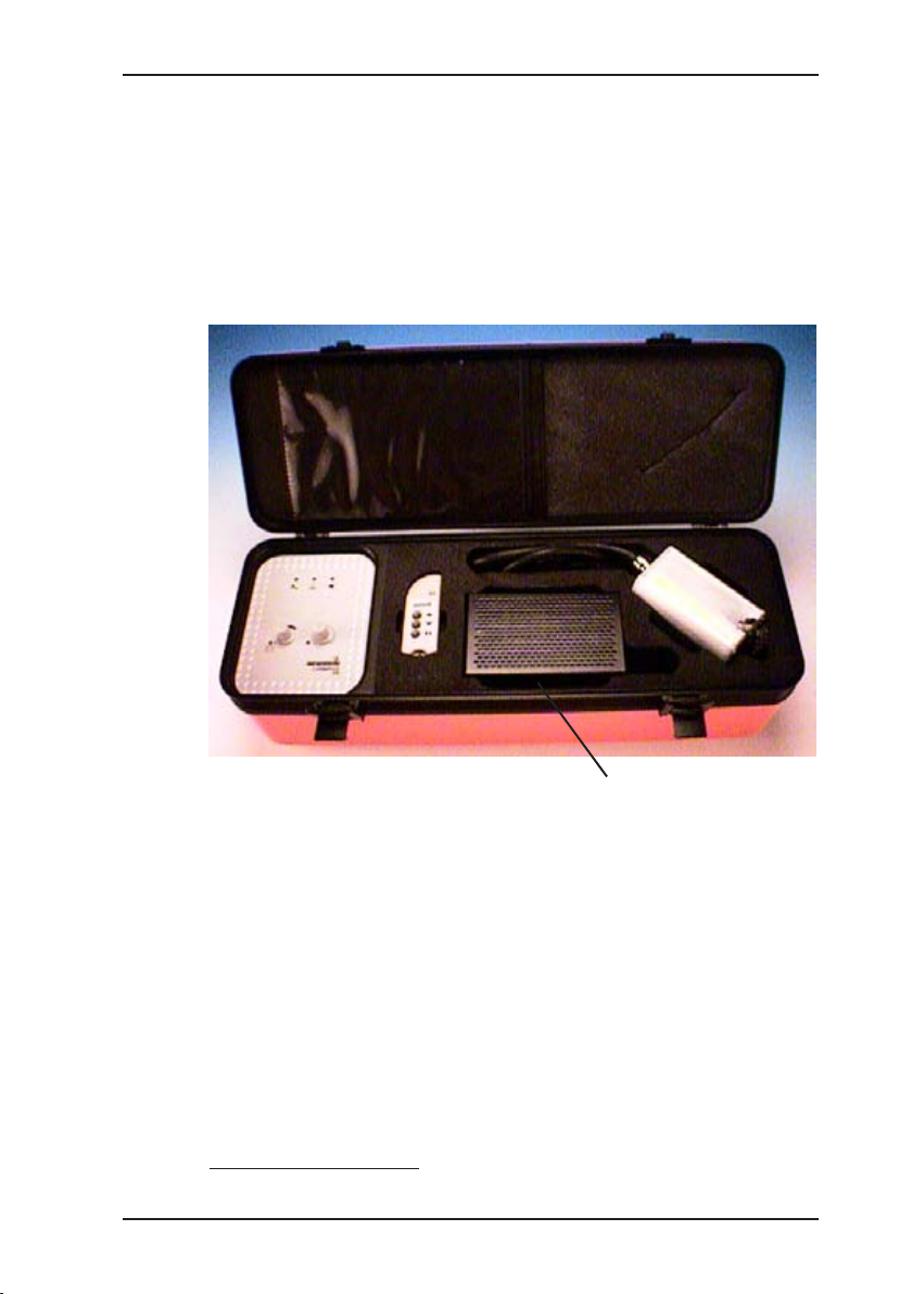
3 COMBIPHON system
3 COMBIPHON system
The following describes the various system components as well
as their intended usage.
The described system elements are laid out in the carrying case
so that they can be easily removed for use and stowed away as
well as operated from the case itself.
* see note on page 23
Adhesive label showing software version (e.g., 1.1)*
Picture 5: Generator G5 and its components in the carrying
case
6
3 COMBIPHON system
3.1 Generator G5
The Generator G5 is located on the left of the carrying case. It is
an integral part of the carrying case and cannot be removed. The
control elements of the generator are used to set the frequency
(see Picture 3) and the intensity of the impulse used for detec-
tion. In addition, the control panel is tted with a number of LEDs,
which indicate the following statuses:
Knocker LED LED is lit when the Knocker is connected
to the system and switched on.
Stopper LED LED is lit when the Stopper is connected
to the system and switched on.
Booster LED without function
Battery LED This LED indicates the following ope-
rating states:
green (on): normal operation
red, ashing: under voltage
green, ashing: charging
green, double ashing: buffering

7
3 COMBIPHON system
3.2 Loading the Battery
Note:
To maintain the device in continuous operation, it
should always be connected to an external power
source (e.g., via the car cable L).
Detailed information
In buffer mode the battery is not charged, only monitored.
The battery is charged
once per week,z
when the battery voltage falls below 12 V or z
when the Generator G5, e.g., after use, remains connected to z
an external power source.
Charging is complete when the battery voltage has reached 14.5 V.
If the battery voltage falls below 10 V, the Generator G5 switches
to “standby mode” (all LEDs extinguish; the quiescent current
equals < 7 mA).
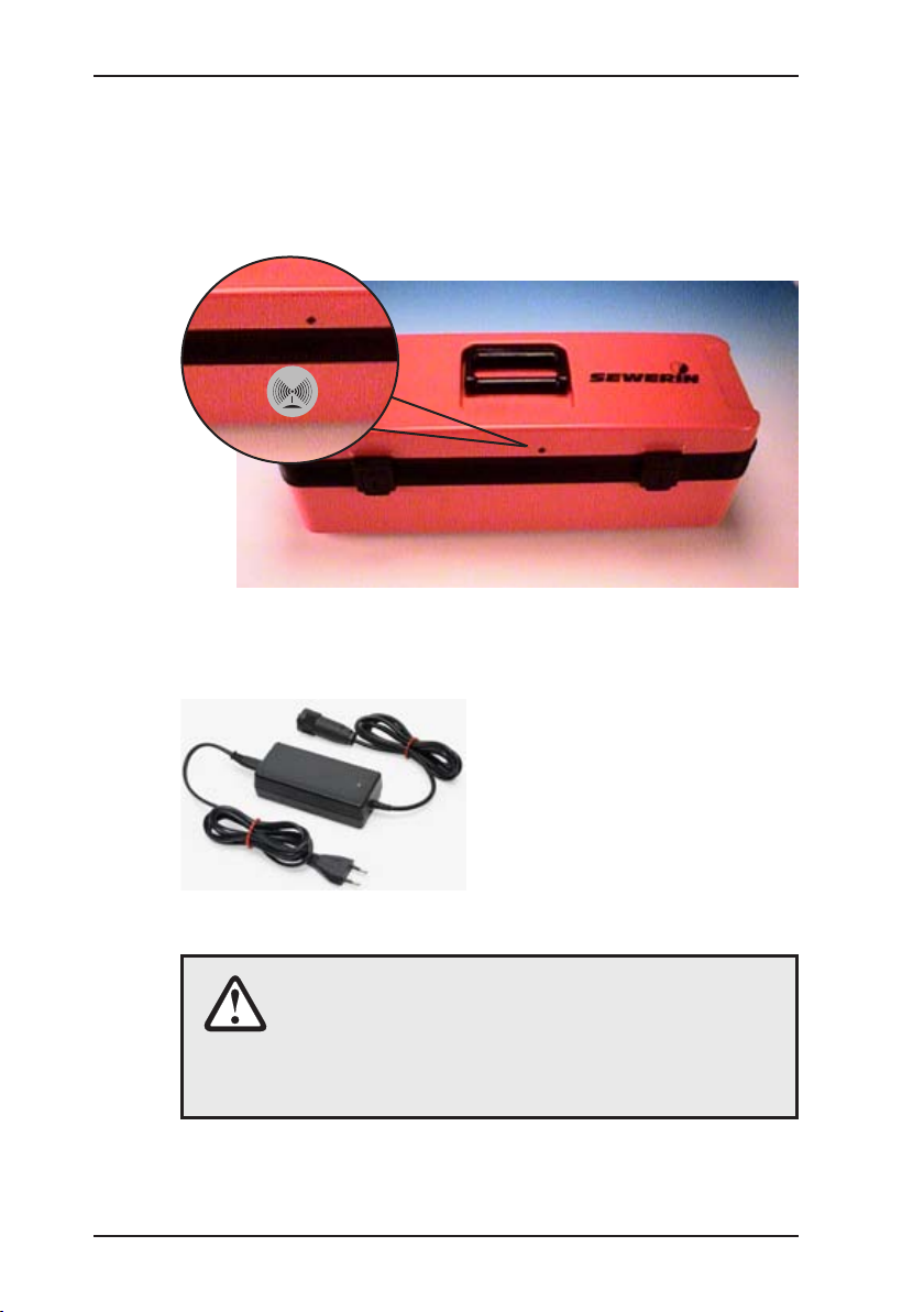
3.3 Generator G5 – Radio
The COMBIPHON Generator
G5 radio is to a great extent
identical to the standard version
described in Chapter 3.1.
The only difference is the sup-
plied remote control and the
corresponding receiver element
on the generator.
With the Stopper, only the
“Pause” key has a function.
Picture 6: Remote control
Increase intensity
Decrease intensity
Pause
SVS
8
3 COMBIPHON system
The remote control allows the intensity (Knocker) to be adjusted.
It is not possible to adjust the intensity beyond that dened by the
position of the adjuster on the generator. Therefore, to achieve
the maximum intensity at the Knocker via the remote control, the
intensity adjuster must also be rotated fully clockwise.
Picture 7: Generator G5 – Radio
3.4 AC/DC adapter L
The AC/DC adapter L is used to
operate or charge the Generator
G5. Comply with the minimum
requirements listed in the techni-
cal data to ensure that the device
operates correctly.
Picture 8: AC/DC adapter L
CAUTION!
When operating the device outdoors, ensure
that the AC/DC adapter L is sufciently protected
against moisture. Otherwise, there is a risk of elec-
tric shock.
9
3 COMBIPHON system
3.5 Car cable L
The car cable L is located in the carrying case in the compartment
to the right of the generator (see Picture 1), below the AC/DC
adapter L. It is used to supply the Generator G5 via the supplied
AC/DC adapter L or a car battery.
Picture 9: Connection to mains supply or car battery
Note:
Before connecting the cable to the AC/DC adapter L,
unscrew the red adapter cap on the cable connector.
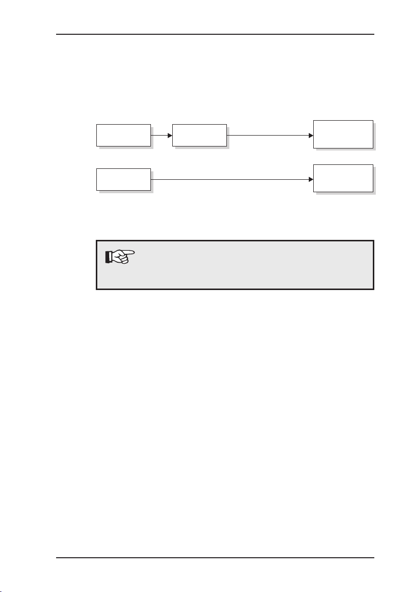
230V~
Mains supply
~
12 V
Car battery
Car cable L
Car cable L
Generator
G5
Generator
G5
AC/DC
adapter L
10
4 Knocker
4 Knocker
The Knocker is located on the right-hand side of the carrying case.
This device is an oscillator which places service pipes under os-
cillation. For more detailed information about pipe and leakage
detection, refer to the operating instructions of the receiver (e.g.,
AQUAPHON).
The Knocker can be attached to pipes with a diameter up to
120 mm using the supplied chain attachment.
Picture 10: Knocker

11
4 Knocker
4.1 Knocker – Starting and operating
Carry out the following steps to put the Knocker into operation.
Using the chain attachment, attach the Knocker to the pipe1.
whose course is to be located.
Connect the Knocker to the Generator G5.2.
Switch on the Generator G5 using the ON/OFF switch (see 3.
Picture 3) on the generator’s control panel.
Take the device you want to use for electro-acoustic water leak 4.
detection (e.g., AQUAPHON), and put it into operation.
Use the adjuster on the Generator G5 to control the transmit-5.
ted knock impulse. We recommend to rotate both adjusters to
the central position, and then adjust the knock impulse to the
local conditions.
4.2 Working with the Knocker
The following provides a few instructions and tips that will make
your work with the Knocker easier.
Detection can be signicantly inuenced by the following fac-
tors:
Ground surfacez
Soil densityz
Background noisesz
When adjusting the intensity of the impulse, take the local condi-
tions into consideration.
After switch-on, rotate both adjusters to the central position.
Then adjust the impulse step-by-step until it suits the local con-
ditions.
For detection in the close vicinity of the Knocker, we recommend
that you do not select a too high frequency or intensity since, for
example, house walls transmit the oscillations, thus making pre-
cise detection difcult.
12
4 Knocker
4.3 Maintaining the Knocker
Note:
Repairs* to the device should be performed by
SEWERIN Service or by a competent person. Re-
habilitation* are to be carried out using only original
SEWERIN spare parts.
CAUTION!
The connectors of the oscillator and the AC/DC
adapter L are to be connected to the Generator
G5 in a dry and clean state. Disregarding this can
cause malfunctions and high wear and tear of the
contacts.
Note:
If the inside of the case becomes damp, store the
device with the case open. Rising damp can cause
damage.
* According to DIN 31051:
Servicing: Determining the actual state
Maintenance: Measures for ensuring the should-be state
Repairs: Measures for restoring the should-be state
Rehabilitation: Servicing, maintenance and if necessary repairs

13
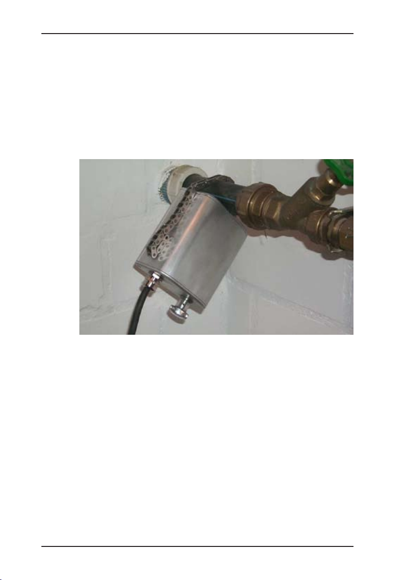
5 Stopper
5 Stopper
The Stopper is a separate system component that is not stored
in the carrying case (see Picture 2).
The Stopper creates a pressure wave by rapidly opening and
closing the pipe. Main pipes (water) require more energy to be
placed under oscillation. The water column is placed in motion
by extracting water from a hydrant. A special shut-off element
known as the Stopper slows down the motion of the water col-
umn at regular intervals. The resulting pressure waves propagate
along the pipeline and can be detected over long distances. The
intensity of the generated pressure wave can be adjusted via the
valve on the device.
CAUTION!
If the set pressure waves are too large, damage to
the pipeline can occur.
Always begin operation with the lowest intensity.
Then increase the intensity as required step-by-step
keeping the local conditions in mind.
Picture 11: Stopper, stand pipe, ushing adapter
14
5 Stopper
5.1 Stopper – Starting and operating
Note:
Comply fully with the following instructions when
starting and operating the Stopper. Note that Her-
mann Sewerin GmbH cannot be held liable for dam-
age caused by non-compliance.
Connect the standpipe with the ushing adapter to the hydrant 1.
under professional guidance. Always ush out the hydrant
and the pipeline to prevent contamination and foreign particles
from collecting inside the device.
After ushing, close the shut-off valve, and remove the ush-2.
ing adapter.
Connect the Stopper to the standpipe3. under professional
guidance.
Connect the connection cable of the Stopper to the Generator4.
G5 (Oscillator connection, see Picture 1).
Rotate the intensity adjuster (see Picture 13) fully clockwise, 5.
i.e., to the lowest intensity.
CAUTION!
Always begin operation with the lowest intensity.
Then increase the intensity as required step-by-step
keeping the local conditions in mind (e.g., state of
the pipelines). The manometer on the standpipe indi-
cates the actual pressure for monitoring purposes.
6. Open the shut-off valve on the standpipe, thus opening access
to the Stopper.
7. Switch on the Generator G5 using the ON/OFF switch (see
Picture 2) on the generator’s control panel.
8. The device is now operating. Adjust the intensity carefully to
suit the local conditions.
9. Take the device you want to use for electro-acoustic water leak
detection (e.g., AQUAPHON), and put it into operation.
Other manuals for COMBIPHON
1
Table of contents
Popular Industrial Equipment manuals by other brands


Festo
Festo Distributing Pro Station operating instructions

ERICO
ERICO TDSGAPC14 quick start guide

Master
Master MS Seeds Instructions for use and maintenance

Hanskamp
Hanskamp MultiFill 003-561-005 Installation and operating instructions

Enerpac
Enerpac Pull-pac BRP106C instruction sheet

Siemens
Siemens 3VA913-0QA00 Series operating instructions


