pozyx Enterprise Anchor V2.1 User manual
1
Accurate Positioning
Enterprise Anchor V2.1
USER MANUAL
v1.5, 2022-06-28

2
Contents
Contents .................................................................................................................................... 2
1 Foreword ............................................................................................................................ 3
2 Disclaimer .......................................................................................................................... 3
3 Note to Operator .............................................................................................................. 3
4 Safety ................................................................................................................................. 3
5 About this Manual ............................................................................................................ 4
5.1 Audience ................................................................................................................................................... 4
5.2 Copyright .................................................................................................................................................. 4
5.3 Revision History ...................................................................................................................................... 4
6 Overview ............................................................................................................................ 5
7 General Technical Specifications ..................................................................................... 6
8 Installing the Anchor ........................................................................................................ 6
8.1 Mounting Anchors ................................................................................................................................ 6
8.2 Connecting Cables ................................................................................................................................ 8
8.3 Powering the Anchor ............................................................................................................................ 9
8.4 Anchor Headers ................................................................................................................................... 10
8.4.1 Mounting the IP66/67 header .............................................................................................. 11
8.4.2 Mounting the IP20 header ..................................................................................................... 12
8.5 Best Practices for Anchor Placement ........................................................................................... 12
8.5.1 Specific guidelines for 2D positioning: .............................................................................. 13
8.5.2 Specific guidelines for 3D positioning: .............................................................................. 13
8.6 Anchor Activation ............................................................................................................................... 14
8.6.1 UWB functionality ...................................................................................................................... 14
8.6.2 Bluetooth functionality ............................................................................................................ 14
9 Troubleshooting .............................................................................................................. 15
10 Ordering information ..................................................................................................... 15
11 Disposal ............................................................................................................................ 16
12 Regulatory information .................................................................................................. 16
12.1 CE Compliance Statement ............................................................................................................... 16

3
1 Foreword
Please read this manual carefully before using the product. Do also read and follow
instructions from “operator” or “licensee” applicable to the specific installation.
For best possible performance, continuous satisfactory safe operation, read and understand
these instructions thoroughly before operating your equipment.
2 Disclaimer
The information, instruction, and parts listed are applicable and current on the date when
issued. Pozyx reserves the right to make changes without prior notice.
3 Note to Operator
It is the operator’s responsibility to see that any person involved with the use or operation of
this equipment follows all safety and operational instructions. Under no circumstances
should this equipment be used if the equipment is faulty or the operator does not
completely understand the operation of the equipment.
4 Safety
All Pozyx equipment should be used with the greatest care and in accordance with all local
safety regulations. It is prohibited to modify, open up, replace or exchange parts, change
factory settings or perform any other action on Pozyx equipment that deviates from the way
it was delivered. Doing so may present a hazard and will void any warranties.
Under no circumstances can Pozyx be held liable in any way shape or form for any defects,
damages, injuries, direct or indirect, that are the result of handling, using, installing or any
other use of the equipment and failure to observe all necessary safety guidelines.
4
5 About this Manual
5.1 Audience
This manual is intended for users of the Enterprise Anchor V2.1 in conjunction with the Pozyx
Enterprise System. Any other use outside of the system is deemed incompliant and will void
any warranties of the anchor, tag, system, or any Pozyx hardware.
5.2 Copyright
All rights reserved. No part of this document may be reproduced or transmitted in any way
or shape be it, electronic, mechanical, photocopying, recording, or otherwise, without the
express prior written permission of the publisher.
For information on getting permission for reprints and excerpts, contact POZYX NV. The
content and illustrations are subject to change without prior notice.
5.3 Revision History
Release Date Revision Remarks
202
2
-
0
1
-
25
1.0
Initial release
2022-02-25 1.1 Update of regulatory information
2022
-
03
-
01
1.2
Update of the ISED regulator
y information
2022-03-04 1.3 Update of the FCC regulatory information
2022-05-12 1.4 Update technical specification
2022-06-28 1.5 Update technical specification
5
6 Overview
The Enterprise Anchor captures, preprocesses, and sends location data from tags to the
Positioning Server. It has been designed for optimal Ultra-Wideband performance and
comes with robust casing options (IP20 or IP66/67), making it ideal for industrial
environments. Mounting the Anchor is straightforward with the help of three mounting
brackets.
The Anchor works within the Pozyx Enterprise system and requires an infrastructure of tags,
anchors, switches, and a Positioning Server to accurately and correctly translate tag positions
in a stream of real-time coordinates.
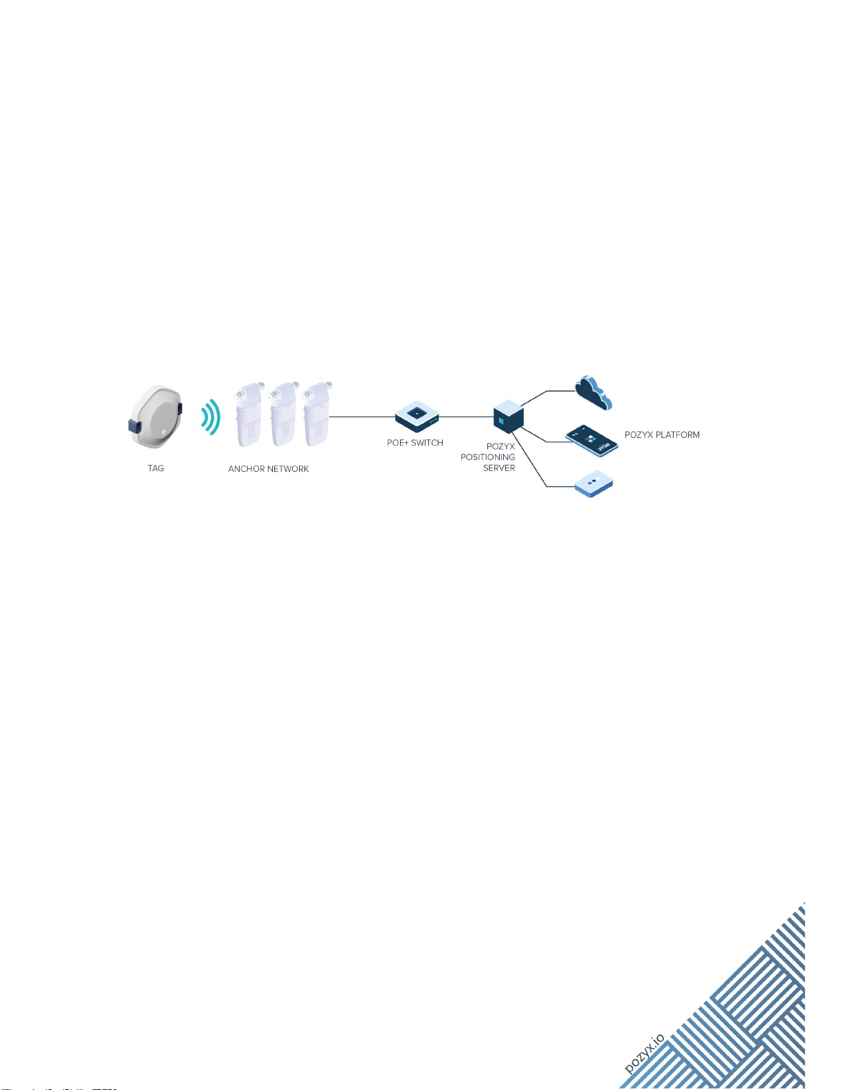
Figure 1 Pozyx Enterprise System Architecture
The Pozyx RTLS architecture comprises three main parts:
• A network of anchors and tags. This network consists of two types of devices:
tags and anchors. The tag is a mobile device used to track the positions of an
asset or person in real time. An anchor is a signal capturing device on a fixed,
well-known position.
• A Positioning Server. This device connects to the anchors via Ethernet. It gathers
all the data received from the anchors and transforms it into a position. By
connecting to the Positioning Server, users can receive the real-time positioning
data.
• The Pozyx web application. The web application is a visual interface to configure
and manage the Pozyx RTLS system. It can be run locally from the Positioning
Server itself or from the Pozyx cloud.
6
7 General Technical Specifications
Parameter
Information
Supported UWB channels
Channel 5, Channel 2 (for licensed customers in Europe)
Bluetooth Bluetooth Low Energy V5.1 ready
Sensors Acceleration, Air Pressure, Supply Voltage, Temperature
Power supply POE/POE+, 3.5W typ, 4.5W max
Certifications
CE
Operating conditions -25 °C to +55 °C
Storage conditions
-
3
0
°
C to +70
°
C
Standard version
Industrial version
Dimensions
158 x 98 x 53 mm 229 x 98 x 59 mm
Weight
170
g
2
7
0 g
Ingress protection IP20 IP66/67
8 Installing the Anchor
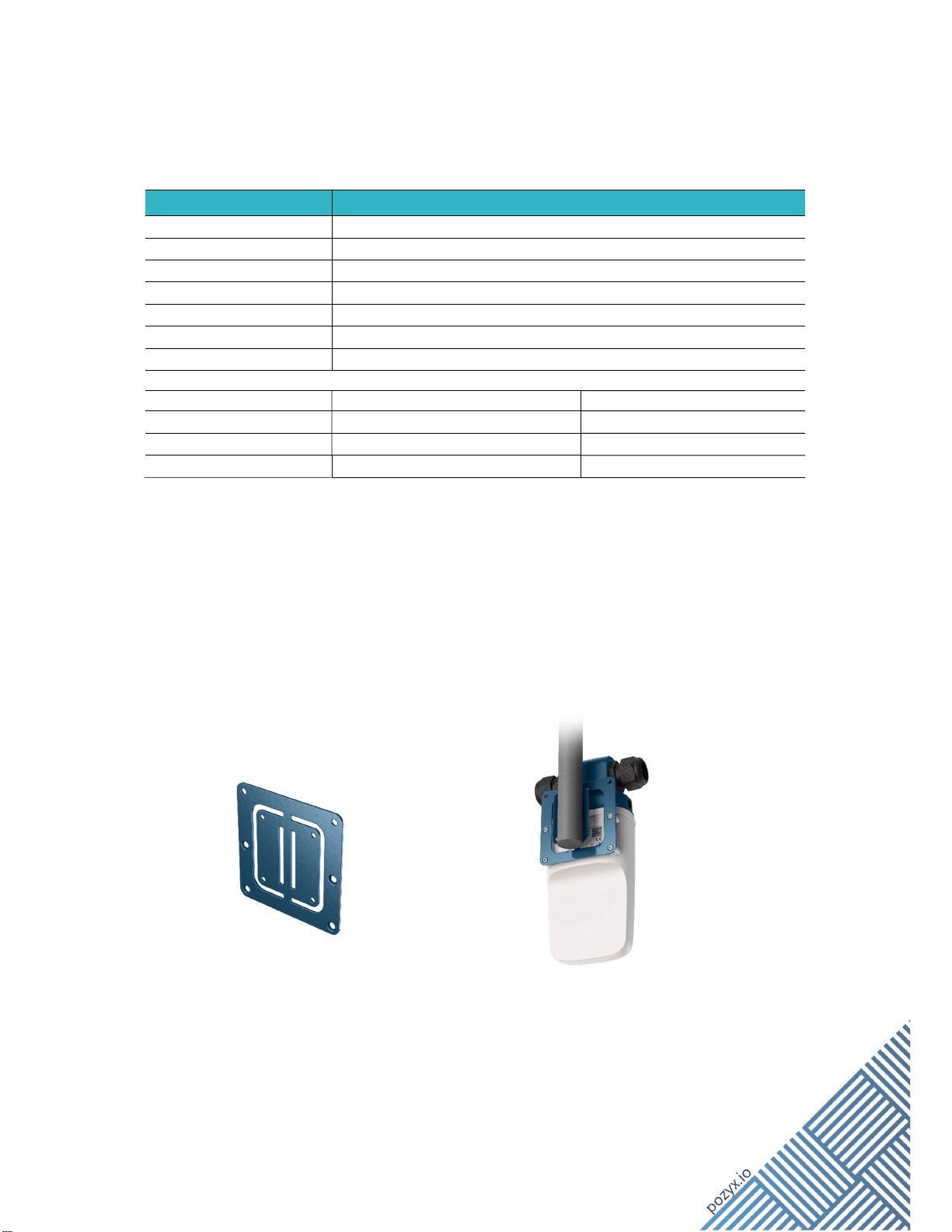
8.1 Mounting Anchors
Mounting brackets allow users to install the Enterprise Anchor V2.1 to a pole, wall or ceiling.
Three types of mounting brackets are available to mount an Enterprise Anchor V2.1:
VESA pole mount (90-020-0001)
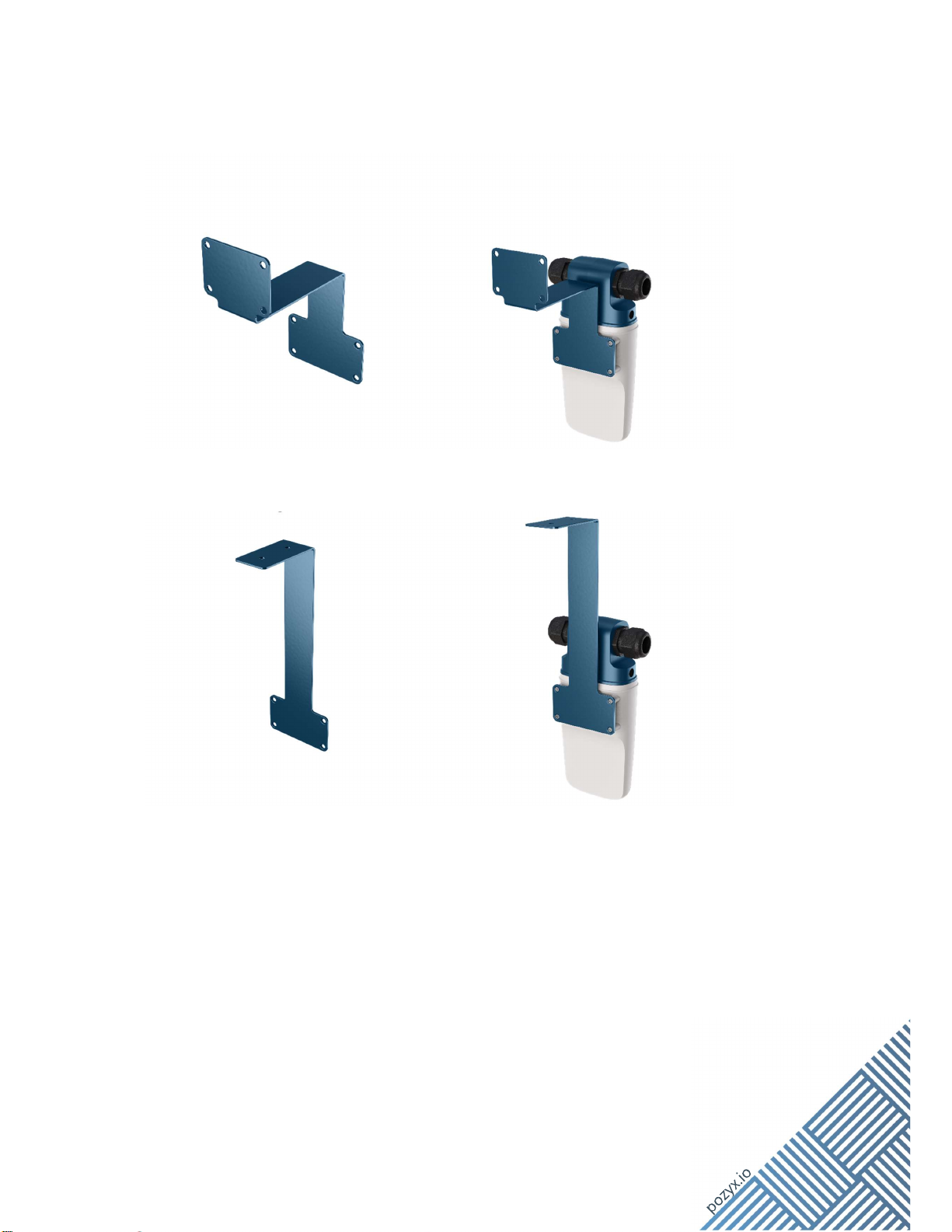
7
VESA wall mount (90-020-0002)
VESA ceiling mount (90-020-0003)
The Anchor is mounted with 4 M4 screws on the mounting bracket.
8
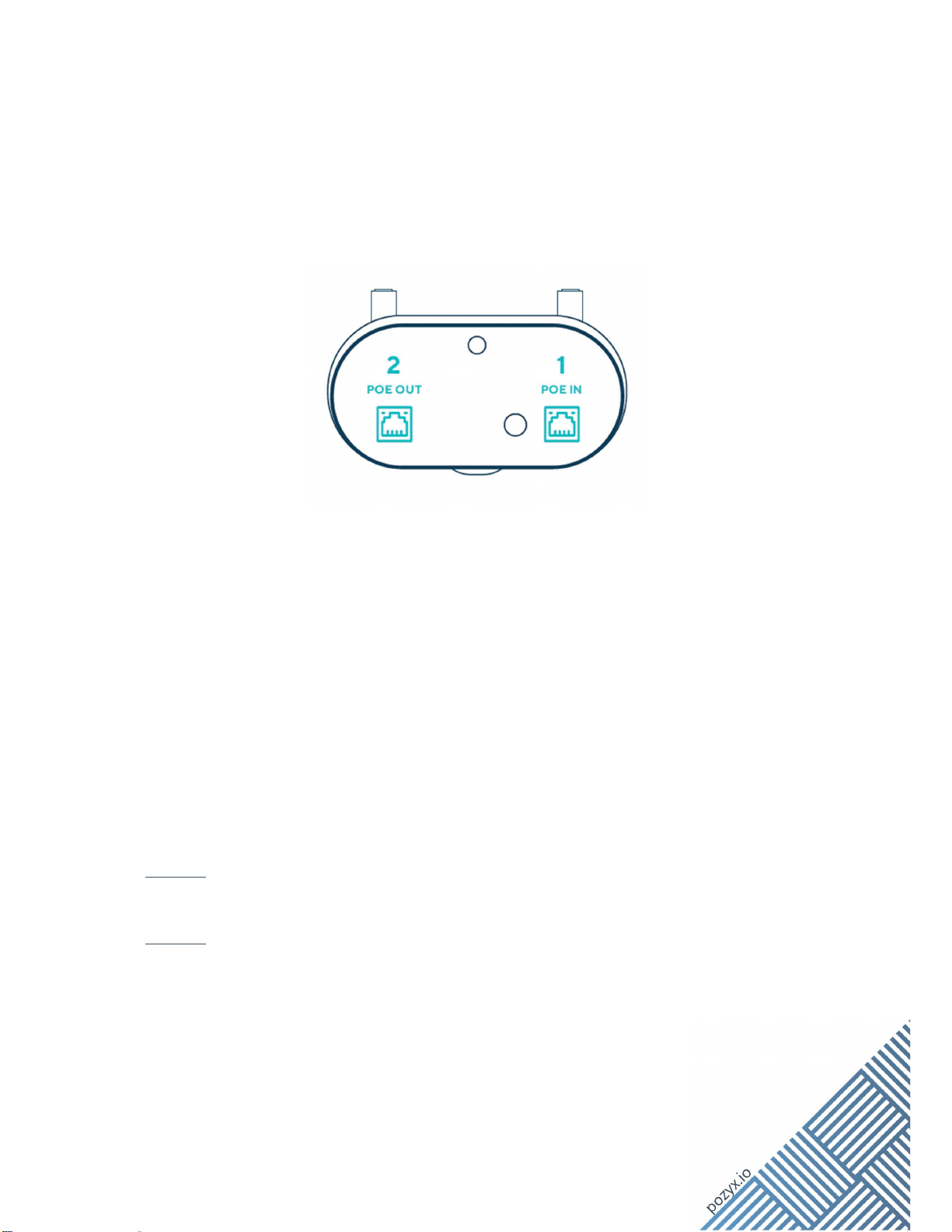
8.2 Connecting Cables
Enterprise Anchors can be connected through Ethernet. Each Enterprise Anchor has 2 RJ45
100Base-T ports. They can be used to link up anchors in sequence which reduces the total
amount of wiring required. We call this Daisy Chaining of Anchors.
Figure 2 Pozyx Anchor PoE ports
The port labeled “1”should be connected to the Positioning Server. This can
implemented either by a direct connection to one of the Anchor ports on the
Positioning Server or by a connection through an Ethernet switch for large setups.
The port labeled “2”can be used to connect anchors in a daisy-chain.
To create a chain of anchors connect the port “2” (OUT in the figure below) of an anchor to
the port “1” (IN in the figure below) of the next anchor in the chain.
Pozyx recommends using Ethernet cables that:
Are Pure Copper (Cu). Do not use Copper Clad Aluminum (CCA)
Are Shielded Foil Twisted Pair (S/FTP)
Are Cat5e (or better)
Are AWG24 (or better). Both AWG 24/1 and AWF24/7 are suited.
Warning: It is advised not to use crossover Ethernet cables: all Ethernet cables should use
the T568B wiring specified in the TIA/EIA-568 standard.
Warning: For system stability it is advised to connect only anchors (and network switches
solely used to aggregate Anchors) to the ports labeled “Anchor network” on the Positioning
Server.
9
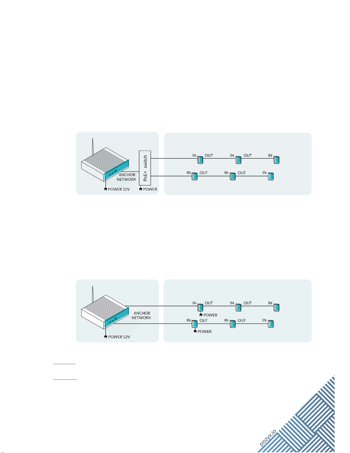
8.3 Powering the Anchor
There are two options to power an Enterprise Anchor:
Using Power-Over-Ethernet (PoE/PoE+). This option requires that an Ethernet
switch with PoE capability is placed between the Positioning Server and the first
anchor in a daisy-chain. Each anchor will provide power on the outgoing Ethernet
cable for the next anchor in the chain. The Ethernet cable that provides power to the
anchor must be connected to the port labeled “1”.
Remark: In general, 4-5 anchors (depending on the installation cabling and taking the
environmental conditions into consideration) is the maximum for a chain when powered
through a PoE+ Switch, more could cause networking issues. Be sure to use shielded
Ethernet cables to eliminate cross talk.
Local power DC jack: This option uses an external AC/DC convertor to power the
first anchor in a daisy-chain.
Warning: It is not allowed to power an Enterprise Anchor through the Ethernet Port 2.
Warning: Make sure that you use the correct ports to connect the incoming and outgoing
Ethernet cables on the Enterprise Anchor.
10
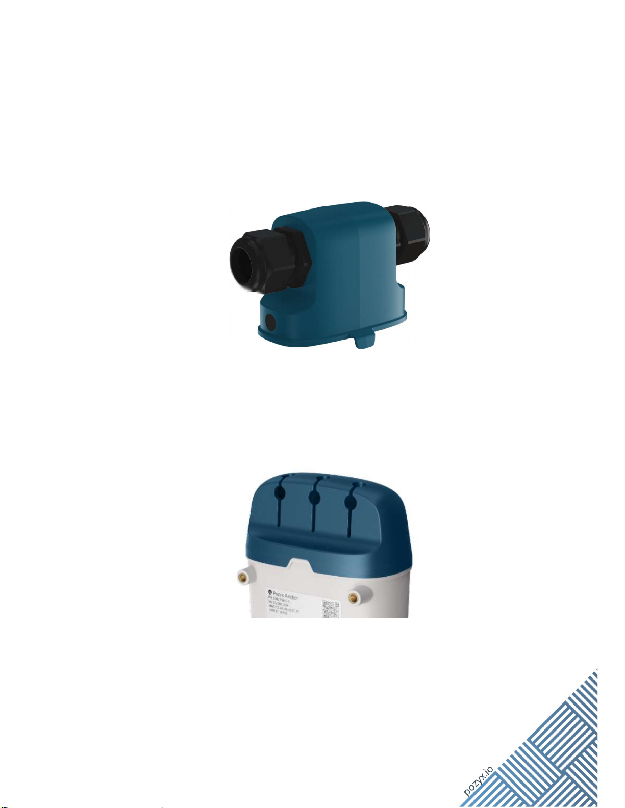
8.4 Anchor Headers
Two types of headers are available for the Enterprise Anchor:
The header 90-010-0101 provides IP66 and IP67 ingress protection to the
Enterprise Anchor. The Ethernet cables enter the header sideways.
The header 90-011-0001 can optionally be used to guide the external cables. The
ingress protection level of this solution is IP20. The header allows users to route the
cabling upwards from or to the backside of the Enterprise Anchor.
11
8.4.1 Mounting the IP66/67 header
1. Place the RJ 45 connector on the Ethernet cable according to the T568B convention
when using an Ethernet cable without pre-confectioned connectors.
Warning: Make sure that the RJ45 connectors are suited for the deployed Ethernet cable.
2. Place the tightening nut over the Ethernet cable.
3. Place the grommets over the Ethernet cable.
4. Pull the Ethernet cable thru the cable glands.
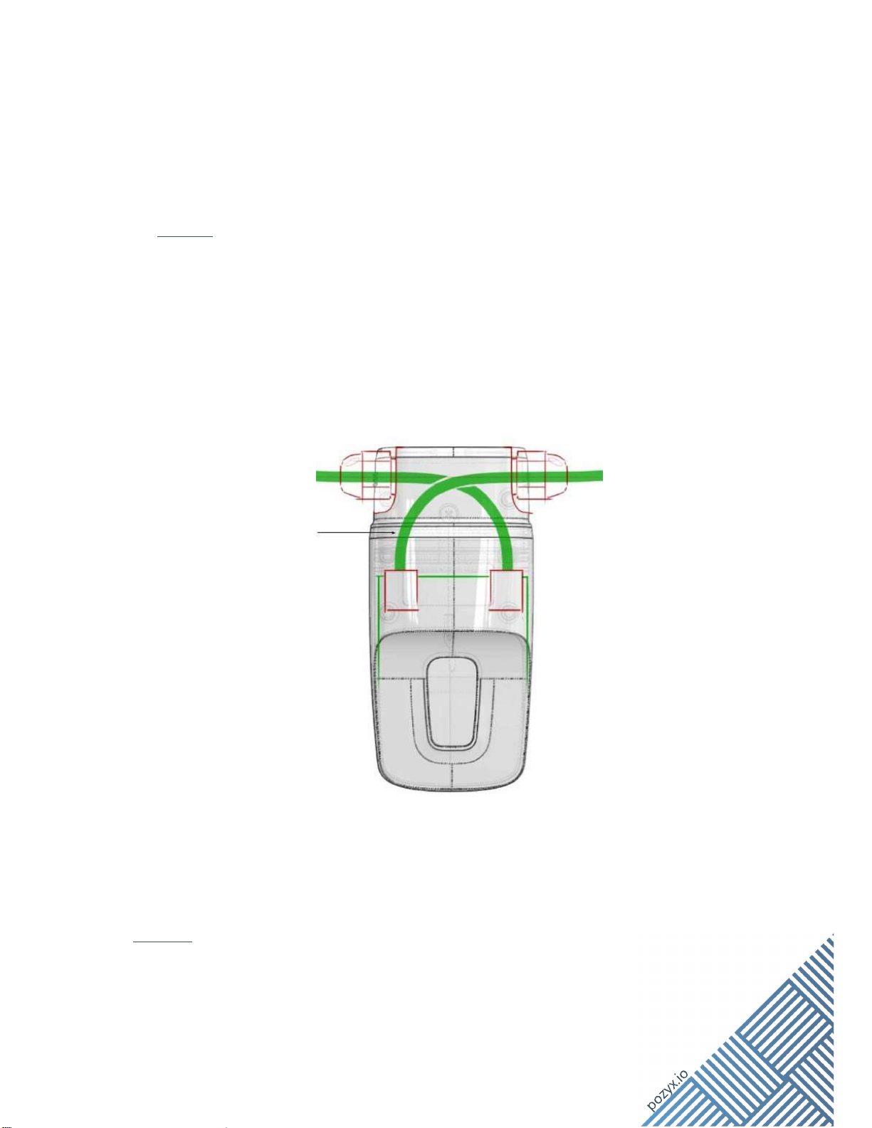
5. Plug the Ethernet connectors into the correct RJ45 jack. Route the Ethernet cables in
a crossed way inside the header as illustrated below.
Figure 3 Anchor Ethernet cable connection
6. Apply the provided lubricant on the O-rings of the IP66/67 header.
Warning: Use only lubricants based on silicone or PTFE.
7. Push the IP66/67 header onto the Enterprise Anchor base module, until the clips snap
on the base module.

12
8. Push the grommets in the cable glands.
9. Screw the tightening nut onto the cable glands until fixed. The maximum torque is
6.0 Nm.
If the header needs to be unmounted, follow the above steps in reverse order.
Warning: To provide IP66/67 protection, the diameter of the Ethernet cables must be tailored
to the grommets provided with the header. The standard cable diameter should be 7 mm
±10%. Contact Pozyx for other options.
Warning: Make sure that the blind grommet, that is provided with the IP66/67 header, is
placed in the right side cable gland if the anchor is the last in an anchor daisy-chain.
8.4.2 Mounting the IP20 header
To mount the IP20 header follow the steps below:
1. Place the RJ45 connector on the Ethernet cable according to the T568B convention
when using an Ethernet cable without pre-confectioned connectors.
Warning: Make sure that the RJ45 connectors are suited for the deployed Ethernet cable.
2. Pull the Ethernet cables and the DC power cable (if used) through the appropriate
holes in the header. Make sure that the cables will not cross after mounting the
header on the Enterprise Anchor base module.
3. Plug the Ethernet connectors into the correct RJ45 jack. When used, also plug the DC
plug into the DC Jack of the Enterprise Anchor
4. Push the header onto the Enterprise Anchor base module.
5. Push the cable into the top or rear exit holes in the header.
6. Readjust the header if it moved during Step 5.
8.5 Best Practices for Anchor Placement
For the most accurate positioning the following generic guidelines apply:
The anchors should have line-of-sight to each other.
An anchor should be placed each 10 m (1 anchor/100 m²). However, this can vary
depending on the environment. In some occasions it can be more or fewer, but we
recommend a maximum anchor separation of 20 m.

13
A tag should be surrounded by anchors in all directions. This can be achieved by
placing an anchor in each corner of the room in which tags are to be positioned.
8.5.1 Specific guidelines for 2D positioning:
• Place the anchors high and in line-of-sight of the user.
Placing the anchor high (on the ceiling or on the walls) increases the chance of
receiving a good signal because there are fewer obstructions. Obstructions generally
have a negative influence on the accuracy of the range measurements which has a
direct effect on the positioning accuracy.
• Spread the anchors around the user. Don't place them on a straight line.
• For range-based systems, single range measurements will only give information in a
single direction. This direction is exactly the direction from the user to the anchor.
Because of this, it is best to spread the anchors such that they cover all directions. If
the anchors are all on a straight line, the positioning error will be very large: A small
change in radius (for example due to noise), will result in a very large change in the
position of the intersection(s). In other words, the error on the range measurements is
amplified! This is the same principle as in GPS, where it is called the geometric dilution
of precision (GDOP).
• Make sure each anchor sees at least two, but preferably more neighboring
anchors at a distance of not more than 15 to 20 meters, or even less in environments
with many obstacles. It’s very important that the clocks of the anchor are accurately
synchronised with each other, and this happens through UWB. It’s therefor important
that not only the tags have line-of-sight to the anchors, but also that the anchors have
a line-of-sight with each other.
• Place anchors vertically, with the connectors at the top. This keeps the antenna at
the bottom.
• Materials like metal, water and wires should stay away from the anchors,
especially the antenna: Within a few centimeters from the antenna, there should be no
metal at all, not even small screws.
• It is recommended to have a separation of 20 cm between the anchor and walls.
Our mounting equipment can be used to achieve this.
8.5.2 Specific guidelines for 3D positioning:
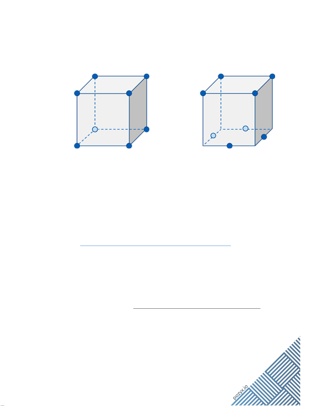
• Keep to the guidelines from above but place anchors at different heights:
The accuracy of the z coordinate will highly depend on the spread in heights of your
anchors. Ideally, it is advised to place your anchors in the shape of a cube around your
positioning zone as shown below. Try to maximize the distance between the lower and
higher anchors.
14
• Twist the base surface of your cube 45 degrees as compared to the top surface:
Twisting the base surface will reduce the 3D convex hull of the anchors (e.g. the
bottom corners of the cube are outside of the convex hull), but it will generally give
you a higher chance of line-of-sight between a tag and the anchors. E.g. when your
body is blocking 1 corner of the room it will just block line-of-sight with 1 anchor
instead of 2. Furthermore its better for the tag to be surrounded by anchors from as
much directions as possible.
Place the bottom anchors upside down as this will point the antenna upwards
(= towards the tags).
Always check https://docs.pozyx.io/enterprise/choosing-the-anchors-locations for the latest
guidelines.
8.6 Anchor Activation
8.6.1 UWB functionality
The general description of the Enterprise Anchor setup and configuration and as part of a
positioning system can be found at https://docs.pozyx.io/enterprise/installing-the-anchors.
8.6.2 Bluetooth functionality
The use of the BLE functionality is not supported yet.
15
9 Troubleshooting
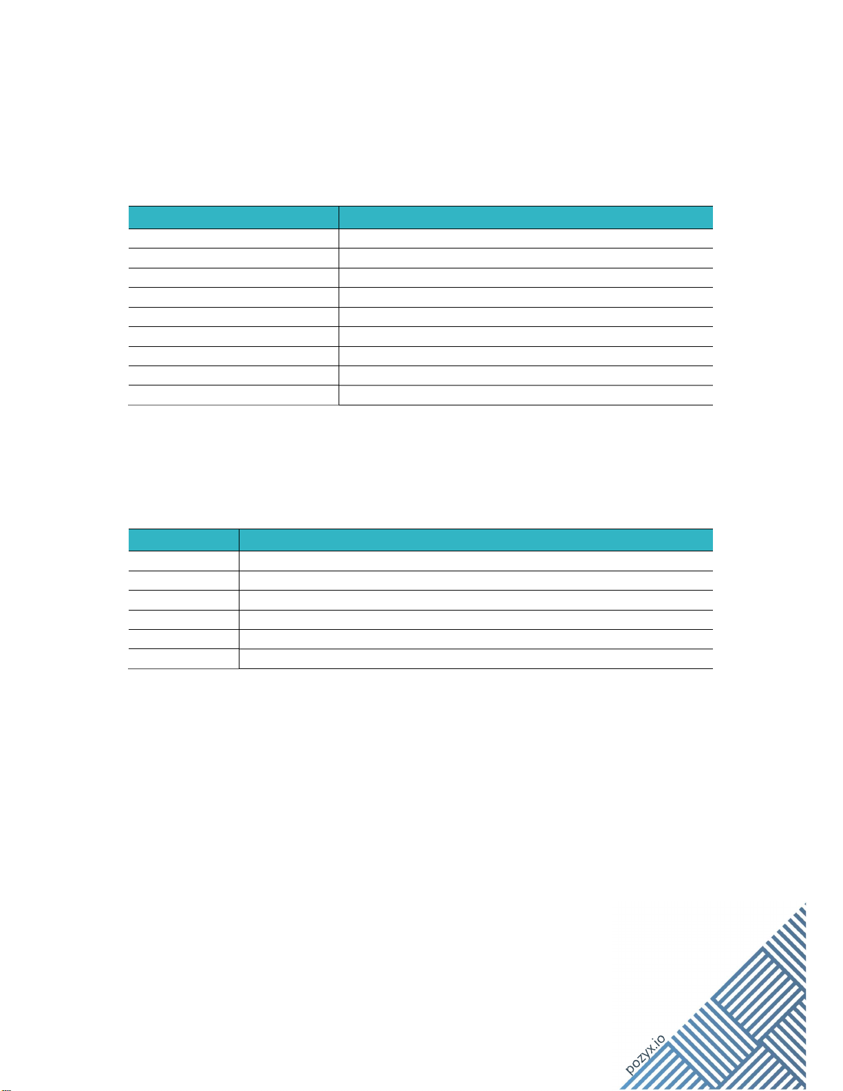
The Enterprise Anchor has a LED with 3 color options with the following state indications:
Parameter Information
LED off Anchor powered off or general malfunction
Solid blue
Startup
or Maintenance
mode
Solid red No Ethernet link
Blinking orange
Link
on Ethernet interface
established
Solid orange IP address obtained
Blinking Green
Anchor
o
perational,
no UWB activity
present
Solid Green Anchor operational, UWB activity present
Blinking red
General malfunction
Blinking blue Pozyx reserved mode
10 Ordering information
Par
t Number
Description
10-002-0012 Enterprise Anchor V2.1
90-010-0101 IP66/67 cover for the Enterprise Anchor
90-011-0001
IP20 header for the
Enterprise Anchor
90-020-0001 VESA pole mount (screws & washers included)
90
-
020
-
0002
VESA wall mount (screws & washers included)
90-020-0003 VESA ceiling mount (screws & washers included)

16
11 Disposal
When the product reaches end of life, dispose it properly in accordance with local laws and
regulations.
Disposal of the packaging material
(EU directive 94/62/EC on packaging and packaging waste)
This marking indicates that the product’s packaging material can be
recycled.
Disposal of this product
(EU directive 2012/19/EU on Waste Electrical & Electronic Equipment)
This marking on the product, accessories or literature indicates that the
product and its electronic accessories (e.g. AC/DC convertors) should not be
disposed of with other household waste at the end of their working life. To
prevent possible harm to the environment or human health from
uncontrolled waste disposal, please separate these items from other types
of waste and recycle them responsibly to promote the sustainable reuse of
material resources.
Household users should contact either the supplier where they purchased
this product, or their local government office, for details of where and how
they can take these items for environmentally safe recycling.
Business users should contact their supplier and check the terms and
conditions of the purchase contract. This product and its electronic
accessories should not be mixed with other commercial wastes for disposal.
Please contact the local municipal office for information on the nearest recycling station.
12 Regulatory information
12.1 CE Compliance Statement
The manufacturer, Pozyx NV, Vrijdagmarkt 10/201, 9000 Gent, Belgium declares that the
product:
10-002-0012: Pozyx Anchor V2.1 with BLE
is conform to the following Directives:
2014/53/EU (Radio Equipment Directive)
2011/65/EU (ROHS), amended by 2017/2102/EU and 2015/863/EU
See the CE Declaration of Conformity for full details on the applied standards.
This manual suits for next models
1
Table of contents
Popular Industrial Equipment manuals by other brands


NuAire
NuAire ES-ISCT installation manual

Siemens
Siemens SITRANS LG Series Firmware update

Panblast
Panblast BB120S-2 CORSA II Owner’s Operation and Safety Manual

MBO
MBO SVC 525C Translation of the original operating manual

Panblast
Panblast BP600-3 Product Operating Manual

Indexator
Indexator LINK Series user manual