SF SF-540A User manual

·
SF-540A
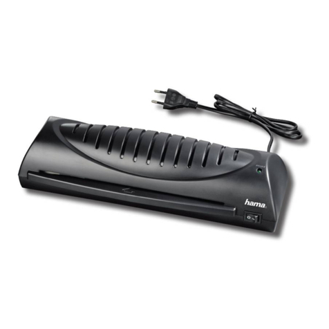
Laminator
Operating Manual

SF-540A 202205
1
Instructions of the operation manual:
★Before operating the laminating machine, please read and
understand the contents described in the manual carefully.
★Please keep this instruction manual for future reference.
★Please pay special attention to the sections marked with warning
symbols in the manual, which are very important for the correct use
and maintenance of the machine and the safety of users.
★With the improvement of product function and software upgrade,
the information of operation manual will be constantly changed and
perfected without further notice. The description and image
involved shall be subject to the actual contents in the packing box.
The company reserves the right to modify and interpret this
instruction manual. We strive to ensure the accuracy of the
instructions and the product functions and features described, but
we do not assume any responsibility for any differences between the
user manual and the product.

SF-540A 202205
2
Contents
1. Safety Precautions ............................................................................... 3
2. Application and characteristics of SF-540A ....................................... 4
3. Schematic diagram of the whole machine .......................................... 5
4. Operating instructions for operation panel ..........................................7
5. Main technical parameters .................................................................11
6. Operating cautions .............................................................................12
7. Assembly of machines .......................................................................13
8. Operating procedure and method of machine...................................18
9. How to use the slitter mechanism ..................................................... 37
10.Application method of upper point line cutter mechanism ............. 38
11. How to use aluminum foil mechanism ............................................39
12.Work to be done after operation ....................................................... 42
13.Film covering process guidance .......................................................43
14.Common problems in operation and solutions................................45
15.Technical service .............................................................................. 47

SF-540A 202205
3
1. Safety Precautions
1.1 Before operation of this machine, please note if the supply voltage
used matches the rated operating voltage of the machine. Use the supply voltage
consistent with the rated operating voltage of this machine. Never misuse the
supply voltage;
1.2 Please do not use damaged power cord or broken power socket;
1.3 The power supply should provide reliable grounding protection;
1.4 In order to avoid electric shock accident or machine failure, please do not
spray water or other liquids on the machine;
1.5 Please do not touch the surface of the steel roller with your hands to
avoid scalding skin;
1.6 Be aware not to entangle clothes, necktie, hair, necklace, cuffs and
the like into the running machine during the operation, which may cause
unnecessary damage to the machine;
1.7 In the process of film covering operation, please do not put any items other
than the coating on the working panel or the boxes on both sides, so as to avoid
accidental involvement of the articles and damage to the machine;
1.8 In case of fault, people other than professionals shall not attempt to
dismantle the machine for repair. Repair shall be conducted by professionals or
organized by local dealer. Dismantling and repair by unauthorized persons will
adversely affect the normal service and maintenance of the machine;
1.9 The environment for the operation of the unit shall range 10℃—40℃.
Ideal humidity: 55%. The unit should stay away from locations with high

SF-540A 202205
4
temperature (e.g. by air-conditioner), and damp and dusty locations;
1.10 When the machine is running, the operator should not leave his post;
1.11 Please prevent children from using or touching the machine;
1.12 When the machine is out of service for a long time, please cut off
the power supply;
1.13 Please do not change the original configuration of this machine. If the user
makes any changes, we will not take any responsibility for safety.
2. Application and characteristics of SF-540A
2.1 Application of SF-540A:
SF-540A fast laminator laminates printed matter, spray-drawing products,
packing boxes, books and the like, allowing them to resist water, stain and
damage, and providing durability. Featuring compact size, fast and continuous
lamination, automatic parting cut, easy operation, economics and utility, this
unit is ideal for the post production of various types of printed and packing
products.
2.2Performance characteristics
2.2.1Mirror chrome plating roller, oil heating;
2.2.2 Touch screen human-computer interaction display system;
2.2.3 Frequency control system;
2.2.4Electric hydraulic pressure system, film pressure adjustable;
2.2.5 Full automatic paper feeding control system, can overlap;
2.2.6Pneumatic automatic cutting system;
2.2.7Curling-preventing device, preventing laminated paper from curling;
2.2.8Film slitting device;

SF-540A 202205
5
2.2.9Air inflation shaft material roller device;
2.2.10Bronzing winding device;
2.2.11Upper point thread cutter device;
2.2.12Automatic stop function for paper shortage.
3. Schematic diagram of the whole machine
1.Feeder 2.Lifting paper feeding table 3.Foot switch 4. Upper left box
5.Operation display screen 6.Pressure regulating valve 7.Anti roll handle
8.Air expansion shaft and film winding shaft
9.Point line cutter mechanism 10.Slitter mechanism
11.Front guard 12.Vacuum pump switch
3
6
7
8
9
11
1
2
10
12
4
5

SF-540A 202205
6
13.Slitter support plate 14.Emergency stop switch 15.Castor wheel
16.Power switch 17.Power cord 18.Rear receiving tray
19.Right box 20. Tin foil winding mechanism
21. Laminating tension adjusting handle 22. Roll film damping device
19
13
15
16
17
18
20
21
14
22

SF-540A 202205
7
4. Operating instructions for operation panel
4.1 Main page
4.1.1Temperature setting display
temperature value of the laminating roller; the set value adjustment range is "80 ~
140 ℃", and if it is lower than 80 ℃, it will be displayed as "---"; when the button
"+" is pressed, the value of 80 will appear, and the machine will start to heat up.
Press "+" temperature setting value "+ 1" again, and press "+ 5" continuously; press
"- 1" for temperature setting value and "- 5" for a long time. When the machine
starts to heat up, the actual display temperature value changes with the actual
temperature of the laminating roller surface.
1. Temperature setting key 2. Speed setting area 3. Paper length setting key
4. Setting area of cutting value adjustment 5. Laminating roller lifting button
6. Lifting button of traction roller 7. Operation key 8. Stop key
9. Pedal forward button 10. Pedal reverse button 11. Foil 12. Set
5
6
7
8
10
11
3
1
9
12
4
2

SF-540A 202205
8
Note: (1) laminating can be carried out when the actual surface temperature of the
laminating roller reaches ± 5 ℃;
(2) when the heating function needs to be turned off, the set temperature
value should be reduced to 80 ℃ first, and then press the button "-" again.
When "-" appears, it means that the heating function of the machine has been
turned off;
(3) The temperature overshoot will appear in the initial heating, and the
overshoot is about 10 ℃and stable at the set value for about 15 minutes.
Please wait until the temperature value is stable, so as not to affect the film
quality.
4.1.2 Display of set speed value
The speed adjustment range of main roller is 1-20m / min, and the speed of each
gear is 0.5m/min, increasing or decreasing. Press the icon "+" to increase the speed
value, otherwise, press the icon "-" to decrease the speed value;
Note: the speed of slitting roller is not adjustable;
4.1.3 Paper length adjustment setting area
The adjustment range of paper length is 200-1200mm. Press the "+" or "-" button
to change the value by one digit, increase or decrease by 1 mm, and press for a long
time, and the value will increase or decrease in 20 units;
4.1.4 Setting area of cutting value adjustment
Press the "+" or "-" button to change the value by 1 bit, increase or decrease by 1
mm, and long press, the value will increase or decrease in 5 units;
4.1.5 Laminating roller lifting button
The icon is on, the icon is light, and the roller is closed. When the icon is under, the
roller is opened and the icon is dark ;
Note: when the laminating roller is not closed, the machine will not move after

SF-540A 202205
9
pressing the operation button
4.1.6 Lifting button of traction roller
The icon is at the top, the icon is light, the roller is closed, the icon is at the bottom,
the roller is open, and the icon is dark;
4.1.7 Run button
After pressing, the machine starts to work in linkage (i.e. both the cardboard baffle
and the cutting roller can act); when pressed, the icon is light in normal operation,
while it is dark in standby.
4.1.8 Stop button
This button controls the stop of the machine in the linkage state; after pressing the
button, the machine stops working, the icon is light , and the icon is dark during the
operation of the machine.
4.1.9 Pedal forward button
This button is used with the foot switch. Press this button to turn light. At this time,
the machine starts to run when you step on the foot switch (only the main motor
drives the rollers to run at the set speed). Release the foot switch and stop running.
The icon will be dark if you don't press the button. What is the speed setting value
of forward rotation, the actual machine will operate according to this set speed;
Note: (1) this button is usually used when the machine is preheated or debugged;
(2) if the foot switch is used, the cutting roller of the machine will not work;
(3) When the pedal forward rotation button is on, press the operation switch
to start the machine.
4.1.10 Pedal reverse button
This button is used with the foot switch. Press this button to turn light At this time,
the machine starts to run when the foot switch is stepped on (only the rollers driven
by the main motor run). After the foot switch is released, the icon will be dark;

SF-540A 202205
10
Note: there is no speed regulation for pedal reversal, and the maximum speed is 3m
/ min;
4.1.11 Foil
This button can be used when there is no need to cut the coated finished product or
add the gilding device without the action of the slitting roller. If it is pressed down,
it will turn light and the cutting roller will not act; otherwise, it will be dark, and
the cutting roller will work normally;4.1.12 Set button
This button is used to enter the secondary interface. Click once to enter the
secondary page;
Note: this key is invalid during normal operation of the machine. If there is no need
to move the slitting roller, please press this key before running the machine.
4.1.12 Set
This button is used to enter the secondary interface. Click once to enter the
secondary page;
4.2 Setup page
4.2.1 Paper length
It is used to adjust the error between the paper length value recognized by the
system and the actual measured paper length value. The factory setting of this
parameter has been completed, and the operator does not need to adjust it;
4.2.2 count
Record the total number of paper and the operator can read it;
1
2

SF-540A 202205
11
4.2.3 home button
This button is used to return to the home page. Click to return;
5. Main technical parameters
Model
Technical
parameters
SF-540A
Max. size of roll film
0.53m ×3000 m
Film thickness range
17Mic~42Mic
Applicable dimension of reel
for roll film
Φ75mm
Max. O.D. dimension of roll
film
Φ260mm
Applicable thickness of paper
core
Laser printing paper
128~450g/㎡
Printing paper
157~350g/㎡
Max. applicable size of printed
matter
540×760mm
Min. applicable size of printed
matter
297×420 mm
Capacity of paper table
500mm
Speed regulation range
1~20m/min
Temperature regulation range
80~140℃
Preheating time
20℃At room temperature 10min(100℃)
Operation and display system
Touch screen
Pressurization mode
Hydraulic pressure
Heating mode
Oil heating
Laminating roll diameter
Upper roll
High gloss chromium plating
160mm
Lower roll
Silicon rubber 100mm

SF-540A 202205
12
Paper overlap accuracy
±2mm
Rated input power
7000W
Rated input voltage
AC 3P/N/PE 400V,50/60Hz
Net weight of complete machine
445Kg
Gross weight of machine
540Kg
Physical dimensions of machine
(L×W×H)
2150×960×1500 mm
Machine transport dimensions
(L × W × H)
1500×1180×1350 mm
※Recommended specifications of air pump: air storage tank volume: ≥ 50L,
exhaust capacity: ≥ 80L / min, power: ≥ 1000kW
6. Operating cautions
6.1 The surface of the hot steel roll of the machine should be kept clean and
frequently wiped in alcohol of high purity, thus eliminating the effect on the
lamination.
6.2 When cleaning the machine, never wipe this machine with corrosive liquid to
avoid damaging the machine body. Use soft dry cloth to wipe the machine.
6.3 After the lamination, cool the surface of the steel roll before
stopping the machine, and lift the front steel roll and the rear rubber roll to avoid
the deformation of the rubber roll surface.
6.4 Never use this machine for other purposes than film overlay. Otherwise, it
may cause accidents or damage to the machine.
6.5The pressure setting value of the pressure gauge of the laminating roller should
not be over 0.6MPa;
6.6When the machine is under 2m / min, the normal working speed should be

SF-540A 202205
13
higher than 2m / min;
6.7When heating, please ensure that the machine is running at a low speed, so as
to ensure that the temperature of the hot roll is uniform;
6.8When the actual temperature reaches the set temperature, please do not rush to
wear the film. Wait about 10 minutes before wearing the film, because there is a
temperature shock.
6.9After laminating, please lower the laminating roller to avoid the deformation
of COTS caused by long-term closure;
6.10High temperature lubricating oil should be applied at intervals between
temperature sensor and steel roller.
6.11 the oil window of negative pressure vacuum pump should be observed
regularly. When the oil level drops, vacuum oil should be added; (as shown in the
figure)
6.12This machine is equipped with the function of automatic stop for paper
shortage. The detection sensor is as shown in the following figure. If there is a
stop during the paper feeding process, please check whether there is no paper here
first;
7. Assembly of machines
7.1Packing box disassembly:
7.1.1Remove the baffle, upper cover and fixed wood strips around the packing box
in turn;
Paper sensor

SF-540A 202205
14
7.1.2Open the plastic cover;
7.1.3Remove the pressing plate and wood strip fixing the fuselage;
7.1.4Remove the machine from the bottom bracket (use forklift, lifting screw and
lifting belt);
7.1.5Place the machine on the flat ground and lock the caster;
7.2Installation of rear paper receiving station
7.2.1Install the tray support rod, as shown in the following figure:
7.2.2Fix the rear paper receiving platform on the support plate as shown in the
figure with hand screws, then turn it over along the direction as shown in the
figure, and support the support plate on the support rod of the machine (the angle
can be adjusted as required);
Paper
receiving
platform
Hand screw
Buttress
Bearing
Strut

SF-540A 202205
15
7.2.3As shown in the figure below, install the side baffle board on the paper
receiving platform with M5 stainless steel hand screw and butterfly nut;
7.2.4As shown in the figure below, install the rear baffle board on the paper
receiving platform with M5 plastic hand screw and baffle mounting rod;
Cardboard
side
M5 plastic hand screw
Butterfly nut
Back board
M5 plastic hand
screw
Baffle mounting rod

SF-540A 202205
16
7.3Installation of material roller support plate and material roller
7.3.1Use M5*20 hexagon socket head screws to install the support plate of the air
inflation shaft feed roller mechanism on the right support plate as shown in the
figure;
7.3.2Install the slitting knife support plates on the left and right support plates of
the machine respectively;
M5*20 socket
head cap screw
Air expansion
film winding
shaft
Slitter support
plate

SF-540A 202205
17
7.4Installation of slitting cutter and upper point line cutter mechanism
7.4.1As shown in the figure, insert the slitting cutter mechanism and the upper
point line cutter mechanism into the support rod respectively;
7.4.2String the support rod into the slitter support plate hole, then install the baffle
and fasten it with m5*16 socket head cap screws;
Cutter
device
M5 Socket head cap screw
Dotted line
knife
Support rod
Slitting knife
Note: two people are required for this installation

SF-540A 202205
18
7.5 Installation of auxiliary working platform;
7.5.1As shown in the figure below, install the auxiliary working platform on the
main paper table;
7.6 Connect the power line of the machine to the power distribution box;
8. Operating procedure and method of machine
8.1 Connect the air supply: turn on the φ6mm compressor air pipe and φ8mm
vacuum pump air pipes are respectively inserted into the air source interface of the
machine (as shown in the following figure):
Socket head cap screw
Air compressor interface
Vacuum pump air source

SF-540A 202205
19
8.2 Connect the power supply of air compressor and vacuum pump.
8.3Turn on the host power switch. (the display is on at this time);
8.4Set temperature and speed
8.4 .1First press the pedal forward button, and then step on the foot switch to make
the machine run;
※Now, the speed shall be set below 2m/min.
8.4.2 Set the required temperature value for operation, and the machine will start to
warm up.
※The temperature value should be set according to the thickness of the coating,
the color of the printed matter on the surface and the working speed. The setting
value should not be too high at the beginning, so as not to affect the laminating
effect.
Vacuum pump power supply
Table of contents


