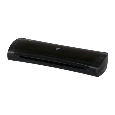
MyBinding GBC Aquila User manual

© 2002 GENERAL BINDING CORPORATION. A L L RIGHTS RESERVED.
Do not duplicate without written permission.
Part number : 930 - ???
AQUILA LAMINATOR
OPERATION & MAINTENANCE
MANUAL

The information in this publication is provided for reference and is believed to be
accurate and complete. General Binding Corporation is not liable for errors in this publication
or for incidental or consequential damage in connection with the furnishing or use of the
information in this publication, including, but not limited to, any implied warranty of fitness or
merchantability for any particular use.
General Binding Corporation reserves the right to make changes to this publication
and to the pr oducts described in it without notice. All specifications and information concerning
products are subject to change without notice.
Reference in this publication to information or products protected by copyright or
patent does not convey any license under the rights of General Binding Corporation or others.
General Binding Corporation assumes no liability arising from infringements of patents or any
other rights of third parties.
This publication is copyrighted © 2002 by General Binding Corporation. All rights
reserved. The information contained in this publication is proprietary and may not be
reproduced, stored, transmitted, or transferred, in whole or in part, in any form without the
prior and express written permission of General Binding Corporation.

Page I© 2002 General Binding Corporation
Operations Manual Aquila
Table of contents
1.0 Safety
1.1 Explanation of symbols 1-1
1.2 General Rules of safety 1-1
1.3 Labels 1-3
Figure 1.3.1 Safety label placement 1-4
2.0 Warranty
2.1 Limited warranty 2-1
2.2 Exclusions to the warranty 2-1
3.0 Specifications
3.1 Film capacity 3-1
3.1 Film core 3-1
3.2 Operating speed 3-1
3.3 Weight 3-1
3.4 Dimensions 3-2
3.5 Electrical requirements 3-1
4.0 Installation
4.1 Setting up the laminator 4-1
4.2 Know your laminator 4-2
5.0 Operations
5.1 Components on the laminator 5-1
5.2 Control panel 5-6
Figure 5.2.1 Control panel 5-5
5.3 Feed table 5-7
5.4 Supply shaft 5-7
5.5 Film alignment 5-8
5.6 Tension knobs 5-8
6.0 Applications
6.1 Film loading and threading 6-1
6.2 Starting an application 6-4
6.3 Speed and temperature guide 6-5
Figure 6.3.1 Chart for degrees Fahrenheit 6-6
Figure 6.3.2 Chart for degrees Celsius 6-6
6.4 Web diagrams 6-7
6.5 Helpful hints 6-8
6.6 Important points to remember 6-9

Page II © 2002 General Binding Corporation
Operations ManualAquila
7.0 Maintenance and troubleshooting
7.1 Cabinets, cover and stand 7-1
7.2 Clean the rollers 7-1
7.3 Troubleshooting 7-2
Figure 7.3.1 Troubleshooting guide 7-3
8.0 Recommended spares
8.1 Spare parts list 8-1

Page 1-1© 2002General Binding Corporation
Operations Manual Aquila
1.0 Safety
CAUTION: Do not attempt to operate your Aquila
Laminator until you completely read and understand
this Operations Manual.
Your safety, as well as the safety of others, is important to
General Binding Corporation. This section contains
important safety information which must be adhered to
while operating, cleaning and performing basic
maintenance in and around the machine.
1.1 Explanation of symbols
INFORMATION: [This symbol is used prior to,
during and/ or after a step. Following this symbol is
important information pertaining to current
subject.]
CAUTION: [This symbol is used prior to a step. The
information following this symbol is to inform you
of how to avoid harm to you, others around you or
to the equipment.]
WARNING: [This symbol is used prior to a step.
The information following this symbol is to inform
you of how to avoid a dangerous situation.]
ELECTRICAL HAZARD: [This symbol is used prior
to a step. The information following this symbol is
to prevent an electrical shock condition that may be
caused by an operators action or machine function.]
1.2 General rules of safety
ELECTRICAL HAZARD: Do not operate the
laminator if power cord is damaged or frayed. You
can be severely shocked, electrocuted or cause a
fire.
WARNING: Do not operate this laminator if you
are not physically, psychologically or emotionally fit.
Do not operate this machine until you have been
trained and read this manual in it’s entirety.
WARNING: Do not wear ties, loose fitting clothes
or dangling jewelry while operating or servicing the
laminator. These items can get caught in the nip and
choke you or you can be crushed or burned.
WARNING: Never tamper with the safety devices
to increase the laminator’s production capacity. In
the event a safety device should fail, never attempt
to bypass it for operation. Consult a service
representative immediately.

Page 1-2 © 2002 General Binding Corporation
Operations ManualAquila
WARNING: Never use this machine for any other
purpose than its intended design and function.
WARNING: Do not make any modifications to this
laminator. Unauthorized changes will void your
warranty and may cause extensive repairs or create
poor output quality.
WARNING: Do not attempt to repair or service the
laminator. Disconnect the plug from the power
receptacle and contact your local sales/ service
representative.
CAUTION: Only use acceptable materials through
this laminator. Unacceptable materials may cause
damage to the rollers or cause poor output quality.
CAUTION: Always observe all warning labels placed
at various points on the laminator. If you do not
completely understand a label, contact your local
service representative for further explanation.
CAUTION: Avoid contact with the heat roller during
operation or shortly after power has been removed
from the laminator.
CAUTION: Do not place the laminator on an
unstable cart, stand or table. An unstable platform
may cause the laminator to fall resulting in serious
bodily injury.
CAUTION: When moving the laminator on a cart
or stand, avoid quick stops, excessive force and
uneven floor surfaces.
INFORMATION: Always disconnect the power
plug from the receptacle to which it is connected and
keep the power supply cord in your possession when
moving the laminator.
INFORMATION: Any concerns for safety or
operation should be brought to the attention of your
local service representative immediately.

Page 1-3© 2002General Binding Corporation
Operations Manual Aquila
1.3 Labels
Safety warning labels are placed at various locations on
the laminator. Do not remove any of these labels. They
are placed for your safety as well as the safety of those
working around you.
Below are illustrations of the safety labels and a description
of their meanings.
Hot rollers
– The safety label below means that you could be burned
and your fingers and hands could be trapped and crushed
in the rollers. Jewelry and long hair could be caught in the
rollers and you could be pulled into them.
CUIDADO!ATTENTION!CAUTION
!WARNUNG
!
RODILLOS
CALIENTES.
PUNTO DE
PINCHAMIENTO.
Mantener manos y
ropa a dis tancia.
ROULEAUX
CHAUDS.
POINT DE
PINCEMENT.
Tenir mains et
vetements a l'ecant.
HOT ROLLS.
PINCH POINT.
Keep hands and
clothing away.
HEISSE
ROLLEN
Klemmgefahr
zwischen Rollen
Hande und
Kleidung ferhalten
One label is placed on each side from the front operating
position just in front of the heat rollers nip.
Electrical hazard
– The safety label below means that you could be seriously
hurt or killed if you open the product and expose yourself
to hazardous voltage.
MUCHO
CUIDADO
!
Riesgo de
choque
e ectrico
No abra
Adentro, no hay
p ezas
reparables
para el usua io.
Mantenimiento
solamente para
personal
cali icado
MUCHO
CUIDADO
!
R sque de
secousse
electrique.
Ne pas ouvrir.
Pas de pieces
reparables par
l'util sateur.
Entret en par
personnel
qua ifie.
WARNING
!WAARSCHUWING
!A ENZIONE
!WARNUNG
!
Electrical shock
hazard.
Do not open.
No user
serviceable
parts ins de.
Refer serv cing to
qual fied se vice
personnel.
Kans op
elektr sche
schok.
Niet openen
Bevatgeen door
gebruik te
repareren
onderdelen.
Door bevoegd
serv ce personeel
la en repareren
Pericolo di
scarica
elettrica.
Nessuna par e
riparab le
da l' utente.
Chiamare un
servizio
di riparaz oni
qualif ca o.
Spannungs fU hre nd
e
Te le.
N cht offnen.
Entha t keine vom
Enduerbraucher zu
warte nde Te le.
Fur servce bitte an
qual fizie rtes
Service-Personal
wenden.
This label is located on the rear panel in the center of the
laminator just below the film supply shaft between the pull
rollers and decurling bar.
Pinch point
– The safety label below means use extreme caution when
placing your hands in the proximity of the pull rollers nip.
You should never place your fingers or other items in this
area while the machine is running.
Use caution in proximity of
pull rollers.
This label is located between the pull rollers and the
decurling bar center of the rollers.
Refer to Figure 1.3.1 Safety label placement for
illustration.

Page 1-4 © 2002 General Binding Corporation
Operations ManualAquila
Figure 1.3.1 Safety label placement
(1) Between pull rollers and decurling bar
CUIDADO!ATTENTION
!CAUTION
!WARNUNG
!
RODILLOS
CALIENTES.
PUNTO DE
PINCHAMIENTO.
Mantener manos y
ropa a distancia.
ROULEAUX
CHAUDS.
POINT DE
PINCEMENT.
Tenir mains et
vetements a l'ecant.
HOT ROLLS.
PINCH PO NT.
Keep hands and
clothing away.
HEISSE
ROLLEN
Klemmgefahr
zwis chen Rollen
Hande und
Kleidung ferha ten
MUCHO
CUIDADO
!
Riesgo de
choque
elect ico
No abra
Adentro, no hay
piezas
reparables
para el usuario.
Mantenimiento
so am ente para
personal
ca if cado
MUCHO
CUIDADO
!
Risque de
secousse
electr que.
Ne pas ouvri .
Pas de pieces
repa ab es par
l'ut lisa eu .
Entre ien par
personnel
qua if e.
WARNING
!WAARSCHUWING
!A ENZ ONE
!WARNUNG
!
Electrical shock
hazard.
Do not open.
No user
serviceable
parts ins de.
Re er serv cing to
qua if ed serv c e
personnel.
Kans op
e ektrische
schok.
Niet openen
Bevatgeen door
gebruik te
repareren
onderdelen.
Door bevoegd
service personeel
laten repa eren
Pe icolo di
scar ca
e ett i ca.
Nessuna parte
riparabi e
dall' utente.
Ch amare un
servizio
di riparaz oni
qual fica o.
Spa nnungs U hrend
e
Te i e.
Nicht offnen.
Entha t keine vom
Endue rb auc her zu
wartende Tei e.
Fur serv ce bi te an
qual fiz er es
Service-Personal
wenden.
Use caution in proximity of
pull rollers.
(2) One on each side of the laminator
(1) Center rear panel below film unwind.

Page 2-1© 2002 General Binding Corporation
Operations Manual Aquila
2.0 Warranty
General Binding Corporation warrants the equipment to
be free from defects in material and workmanship for a
period of 90 days for parts and labor from the date of
installation. This warranty is the only warranty made by
General Binding Corporation and cannot be modified or
amended.
General Binding Corporation’s sole and exclusive
liability and the customer’s sole and exclusive
remedy under this warranty shall be, at General
Binding Corporation’s option, to repair or replace
any such defective part or product. These remedies
are only available if General Binding Corporation’s
examination of the product discloses to General
Binding Corporation’s satisfaction that such defects
actually exist and were not caused by misuse,
neglect, attempt to repair, unauthorized alteration
or modification, incorrect line voltage, fire, accident,
flood or other hazard.
2.1 Limited Warranty
This warranty specifically does not cover damage to the
laminating rollers caused by knives, razor blades, other
sharp objects, failure caused by adhesives or improper
use of the machine. Warranty repair or replacement does
not extend the warranty beyond the initial 90 day period
from the date of installation.
CAUTION: Unauthorized customer alterations will
void this warranty.
THE WARRANTY MADE HEREIN IS IN LIEU
OF ALL OTHER WARRANTIES, EXPRESSED
OR IMPLIED, INCLUDING ANY WARRANTY
OR MERCHANTABILITY OR FITNESS FOR A
PARTICULAR PURPOSE. GBC FILMS GROUP
WILL NOT BE LIABLE FOR PROPERTY
DAMAGE OR PERSONAL INJURY (UNLESS
PRIMARILY CAUSED BY ITS NEGLIGENCE),
LOSS OF PROFIT OR OTHER INCIDENTAL OR
CONSEQUENTIAL DAMAGES ARISING OUT
OF THE USE OR INABILITY TO USE THE
EQUIPMENT.
2.2 Exclusions to the Warranty
This warranty specifically does not cover;
1. Damage to the laminating rolls caused by knives, razor
blades, other sharp objects or failure caused by adhesives.
2. Damage to the machine caused by lifting, tilting and/
or any attempt to position the machine other than rolling
on the installed castors on even surfaces.
3. Improper use of the machine.
4. Damage due from unqualified person(s) servicing the
machine.
Qualified;
•Any engineer that has experience with electrical
and mechanical design of lamination equipment. The
engineer should be fully aware of all aspects of safety
with regards to lamination equipment.
•Any commissioning or service engineer must be
of competent nature, trained and qualified to General
Binding Corporation standards to fulfill that job. This
person will have completed and passed the full service
training course from General Binding Corporation.
•Any General Binding Corporation Technician
and/ or General Binding Corporation Specialist that has
been through the General Binding Corporation service
training course.


Page 2-2 © 2002 General Binding Corporation
Operations ManualAquila
This page intentionally left blank.

Page 3-1© 2002 General Binding Corporation
Operations Manual Aquila
3.0 Specifications
This section provides specific information regarding the
laminator. Any specification not provided must be
requested from GBC.
3.1 Film and sheet size
Film – 1.2, 1.7, & 3 Mil
Core – 1 in. (2.54 cm)
Sheet Size – Min. Width 2 in. (5 cm)
– Max. Width 25 in. (64 cm)
– Min. Length 4 in. (10 cm)
– Max. Length unlimited
3.2 Functions
Speed – 1.0 - 5.0 fpm (30.5 cm - 1.5 m)
Temperature – 32 - 326 OF (0 - 163 OC)
Cooling fans – 5 fan bank system
3.3 Weight
Unpacked – 132 lbs. (60 kilograms)
Shipping Weight – 143 lbs. (64.4kilograms)
3.4 Dimensions (W x H x D)
Refer to Figures 3.4.1 Dimensions.
Machine – 23.75 x 24 x 12 in.
– (60 x 61 x 31 cm)
3.5 Electrical requirements
INFORMATION: Refer to the serial plate located
on the rear of the laminator for specific electrical
ratings applicable to the unit.
Serial plate
Voltage – 110V ~ 60Hz
Current – 10A
Power – 1100 W

Page 3-2 © 2002 General Binding Corporation
Operations ManualAquila
Figure 3.4.1 Dimensions
36.5 in
(94 cm.)
12 in.
(31 cm)
23.25 in.
(60 cm)

Page 4-1© 2002 General Binding Corporation
Operations Manual Aquila
4.0 Installation
This section will guide you through the installation process
of the laminator.
INFORMATION: Shipping damage should be
brought to the immediate attention of the delivering
carrier.
4.1 Setting up the laminator
1. Place the Aquila laminator on a stable flat surface
capable of supporting at least 95 lbs. (45kgs).
The surface should be at least 30 inches high to assure
comfortable positioning during operation.
CAUTION: Too high or too low of an operating
position can lead to serious bodily injury and or cause
poor output quality.
All four rubber support feet should be positioned
completely on the supporting surface.
CAUTION: The laminator is a heavy piece of
equipment and may cause injury and/ or require
extensive repair work if it falls.
The supporting surface may also be large enough to hold
the material being laminated.
2. The laminator should be positioned to allow exiting
film to drop freely to the floor. The drop rollers should
hang over the edge of the table.
CAUTION: Accumulation of laminate immediately
behind the laminator as it exits the equipment may
cause the film to wrap around the pull rollers,
resulting in a “jammed” condition.
3. Avoid locating the laminator near sources of heat or
cold.Avoid positioning the laminator in the direct path of
forced heated or cooling air.
INFORMATION: This effects the performance of
the heating system and could result in poor output
quality.
CAUTION: The stand and laminator should only be
moved across even flat surfaces by two or more
people. Do not turn the laminator on its side or up
side down to move.
4. Connect the attachment plug provided with the
laminator to a suitably grounded outlet only.
Refer to Section 3.6 Electrical Requirements
CAUTION: Avoid connecting other equipment to the
same branch circuit to which the laminator is
connected, this may result in nuisance tripping of
circuit breakers or blowing fuses.

Page 4-2 © 2002 General Binding Corporation
Operations ManualAquila
4.2 Know your laminator
This section will assist you in understanding what and
where items are when referred to in the manual.
Rear
Control Side
Front
Drive Side
Table Interlock Latch
Cabinets
Feed Guide
Control Panel
Feed Table
Heat Rollers
Tension Knobs
Upper Film Supply
Safety Shield
Pull Rollers (Rear)
Idler
Circuit Breaker
Power Cord
On/Off
Fan Switch
Drop Roller Pressure HandleDrop Rollers
Fan Bridge
Decurling Bar
Roller Pressure Handle
Core adapters
Thumb screws
Supply shaft

Operations Manual Aquila
Page 5-1© 2002 General Binding Corporation
5.0 Operation
This section covers the components of the laminator, the
control panel, feed table, supply shaft, film alignment and
tension knobs.
5.1 Components on the laminator
(1) POWER ON/ OFF: This is located at the back of
the control side cabinet. When set to the “I” position,
applies power to the laminator. When set to the “O”
position, removes power from the laminator.
(2) CIRCUIT BREAKER: Electrical safety device,
located under the drive side cabinet cover, can be reset
by the operator if tripped.
CAUTION: If the circuit breaker trips a second time
after being reset, contact your service representative
for assistance.
(2) Circuit Breaker
(1) On/Off
(3) Fan Switch
(3) FAN ON/ OFF: This is located at the back of the
control side cabinet near the drop rollers. When set to the
“I” position with motor engaged, applies power to the fan
bank. When set to the “O” position, removes power from
the laminator.
(4) MAIN ROLLER SAFETY SHIELD: Prevents
entanglement, entrapment and inadvertent contact with
the heat rollers.
INFORMATION: The laminator will operate only
when the safety shield is located in the fully down
position. Power to the motor is removed when the
safety shield is in the raised position.
(5) MAIN ROLLER SAFETY SHIELD INTERLOCK
LATCH: Used to lock the safety shield into position and
activate an interlock switch. This interlock latch is located
on the drive side from the front operateing position.
To raise the main roller safety shield, retract the interlock
latch and lift. Once the interlock latch has been retracted,
power to the motor is removed.
Closed
(4) Main roller safety shield
To close the the safety shield, lower and align the interlock
latch with its locked position. If the motor will revert to its
condition prior to the safety shield being raised.
Raised
(5) Main roller safety shield interlock latch

Page 5-2 © 2002General Binding Corporation
Operations ManualAquila
(6) DROP ROLLER SAFETY SHIELD: Prevents
entanglement, entrapment and inadvertent contact with
the drop rollers.
CAUTION: Never force the pressure handle down.
If the handle does not move smoothly, contact your
local service representative.
(7) DROP ROLLER LEVER: Lever located at rear of
machine,next to drop rollers. Used to engage drop rollers.
Used to pull image over decurling bar to ensure flat output.
(8) FANS: The fan bridge is located in the back of the
machine. The fans are used to cool the finished material.
(7)Drop Roller Lever(14)Drop Rollers
(8)Fan Bridge
(15)Decurling Bar
(9) FEED TABLE: The feed table is used to position
items for lamination.
(10)Table Interlock Latch
(11)Feed Guide
(9)Infeed Table
INFORMATION: The laminator will operate only
when the feed table is installed and the table
interlock latch is properly engaged.
(10) TABLE INTERLOCK LATCH: Used to lock the
feed table into position and activate an interlock switch.
This interlock latch is located on the underside of the feed
table on the drive side from the front operating position.
The table can not be removed without retracting the latch
(11) FEED GUIDE: The feed guide permits alignment
of the item(s) to be laminated and is used to keep longer
items straight.
To position the adjustable guide, loosen the knob on the
top of the guide, slide it to the desired position and tighten
the knob to secure in place.
Knob
Feed guide
CAUTION: The feed guide should be set outside
the width of the film. The film should be completely
inside the sgeet being fed.

Operations Manual Aquila
Page 5-3© 2002 General Binding Corporation
(12) MAIN ROLLER: Teflon coated steel tube. Used
to heat the laminating film and compress the film to the
items being laminated. Heat is provided by an internal
infrared element.
WARNING: Avoid contact with the heat roller. Direct
contact with the heat roller can burn you.
(13) PULL ROLLERS: The bottom pull roller, located
in the middle of the laminator, is motor driven.When Rollers
are in the down position, they simultaneously pull the film
and improve the quality of the laminated item.
(14) DROP ROLLERS: One of the drop rollers, located
at the back of the laminator is also motor driven. They
pull the laminate over the decurling bar correcting any
curl to the finished product.
Motor Driven
(15) DECURLING BAR: The curling bar is located in
the middle of the machine, just past the pull rolls. Each
side of the curling bar has a differant radius to ensure the
output of the finished product lays flat.
(16) IDLER BAR: The idler bar, located near the supply
roll, is used to direct the film to the heat rollers.
(17) SUPPLY SHAFT: The supply shaft holds the film
supply and the core adapters hold the rolls of film on the
film shaft.

Page 5-4 © 2002General Binding Corporation
Operations ManualAquila
(18) COREADAPTERS: The film shaft holds the supply
roll while the core adapters hold the rolls of film on the
shaft.
Core adapters
Locking collars
(19) FILM WEB: Laminating film loaded into the machine
(20) PRESSURE HANDLE: Located on the control
side cabinet. Used to adjust the amount of roller pressure
needed for various laminating applications.
Mounting-
3/16in./ 5mm.
1/8in./ 3mm.
1/16in./ 2mm.
1/32in./ 1mm.
Laminating –
1.5mil/38mic.
Heavy Gauge – laminating films thicker than 1.5
mil (38 mic)
(20)Roller Pressure Handle
CAUTION: Never force the pressure handle down.
If the handle does not move smoothly, contact your
local service representative.
(21) NIP POINT: The point at which two rollers come
into contact. The nip point of the heat rollers is the place
at which the items for lamination are introduced into the
laminator.
CAUTION: Only feed acceptable materials through
the nip of the rollers. Unacceptable materials may
cause damage to the rollers.
Nip Point
(22) FILM TENSION KNOB:Allows the operator to
increase or decrease film web tension as necessary to
reduce curl and wrinkles. Refer to Section 4.6Adjusting
film tension for more information on tension.

Operations Manual Aquila
Page 5-5© 2002 General Binding Corporation
PRESET TEMP SPEED
1.5
3
COLD
C / F
MEASURE
REVERSE
RUN
STOP
(1)
(2)
(3)
(4)
(5)
(6)
(9)
(10)
(11)
(12)
(13)
(14)
(7)
(8)
Figure 5.2.1 Control panel
Table of contents
Other MyBinding Laminator manuals

MyBinding
MyBinding Royal Sovereign CL-923 User manual

MyBinding
MyBinding Dry-Lam Element Series User manual

MyBinding
MyBinding MY2700 User manual

MyBinding
MyBinding GBC Pinnacle 27 User manual

MyBinding
MyBinding RSC 1650C User manual

MyBinding
MyBinding AKILES PROLAM 100 User manual

MyBinding
MyBinding Ultima 65 User manual

MyBinding
MyBinding Element Series User manual

MyBinding
MyBinding GBC H535 Turbo User manual