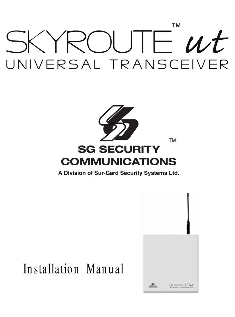
SG Security Communications SKYROUTE User manual

Installation
Manual
Version 1.O

FCC COMPLIANCE STATEMENT
CAUTION: Changes or modifications not expressly approved by Sur-Gard Security Systems Ltd. could void your authority to use this equipment.
This equipment has been tested and found to comply with the limits for a Class B digital device, pursuant to Part 15 and Part 22 of the FCC Rules. These
limits are designed to provide reasonable protection against harmful interference in a residential installation.This equipment generates, uses and can radiate
radio frequency energy and, if not installed and used in accordance with the instructions, may cause harmful interference to radio communications.
However, there is no guarantee that interference will not occur in a particular installation. If this equipment does cause harmful interference to radio or
television reception, which can be determined by turning the equipment off and on, the user is encouraged to try to correct the interference by one or more
of the following measures:
• Re-orient the receiving antenna.
• Increase the separation between the equipment and receiver.
• Connect the equipment into an outlet on a circuit different from that to which the receiver is connected.
• Consult the dealer or an experienced radio/television technician for help.
The user may find the following booklet prepared by the FCC useful: “How to Identify and Resolve Radio/Television Interference Problems”. This booklet
is available from the U.S. Government Printing Office, Washington D.C. 20402, Stock # 004-000-00345-4.
INDUSTRY CANADA COMPLIANCE STATEMENT
This Class B digital apparatus meets all requirements of the Canadian interference-causing equipment regulations.
Cet appareil numérique de la Classe B respecte toutes les exigences de règlement sur le matériel brouilleur du Canada.

Table of Contents
Programming Sections 3
Zone Definition - Sections [01]to[05] ........................... 3
Configuration Options - Section [06]............................ 3
Skyroute Transceiver SID (System ID) - Section [07] ..... 4
Skyroute Test Time - Section [10] ................................ 4
Test Transmission Day Mask - Section [11] .................. 4
Skyroute Transceiver Test Rates - Section [13] ............. 4
Transmission Options [22] ........................................... 4
Individual Event - Transmission Toggle -
Sections [30] to [78].................................................... 4
Activating the Skyroute Transceiver 5
Calling Connect24........................................................ 5
Skyroute Transceiver Trouble Supervision 5
Skyroute Transceiver Trouble Shooting 5
[803] Skyroute Programming
(PC5010/580/1555/5015) 6
For Your Records 13
Appendix A – SIA Reporting Codes 15
Antenna Relocation Diagram 17
Supervised Power Supply Connection 18
Standard Connection with DSC Control 19
Contents
Important Information......................... Inside front cover
Skyroute Transceiver Glossary of Terms... Inside front cover
Introducing the Skyroute Transceiver 1
Specifications............................................................... 1
RF Power Output.......................................................... 1
Power Supply ............................................................... 1
Dimension ................................................................... 1
How the Skyroute Transceiver Works 1
Cellemetry Communication .......................................... 1
Installation 2
Mounting the Skyroute Transceiver............................... 2
Mounting the Antenna.................................................. 2
Wiring Connections ...................................................... 2
Keybus Connection ...................................................... 2
Bell IN Terminal............................................................ 2
Bell OUT Terminal ........................................................ 2
Tamper Terminal .......................................................... 2
Secure Installation ........................................................ 2
Connection Diagram .................................................... 2
Relocating the Antenna 3
Relocating the Skyroute Transceiver 3

Contents
Important Information
Thismanualisbasedontheproductionversionoftheincluded
wireless device. Software changes may have occurred after
the revision of this manual.
Caution
Anychangesormodificationsnotexpresslyapprovedinthis
document could void your warranty for this equipment and
void your authority to use this equipment.
Warning
Only use the antenna provided by DSC / Sur-Gard. The use
of any other type will invalidate the warranty and may be
dangerous.
Customer Service
ForcustomersupportpleasecallSur-Gardtechnicalsupport
at416-665-4494 ext.1, tollfree at1-800-503-5869ext.1,
Skyroute Transceiver Glossary of Terms
The following is a description of various terms used with
regards to cellemetry technology.
Electronic Serial Number (ESN)
The ESN is used to carry data information in a Cellemetry
Network
Mobile Identification Number (MIN)
A10digit decimal numberusedfor registrations andpages.
Page
A transmission that is sent from the Cellemetry Gateway to
the Cellemetry radio.
Registration
A transmission that is sent from the Cellemetry radio to the
Cellemetry Gateway.
System Identification Number (SID)
Identification of the Cellemetry Provider.
Switch Number (SNO)
Switch number the Cellemetry radio uses to transmit pages
to the Cellemetry gateway.
Clearing House
The Clearinghouse is a routing center that automatically
forwards data between Skyroute transmitters and central
stations.

1
Introducing the Skyroute Transceiver
The Skyroute transceiver offers a new wireless communica-
tion method for the transmission of event information using
theCellemetryservice.EventsaretransmittedfromtheSkyroute
transceiver via the Cellemetry network to the Clearing House
and then to the Central Station in a fast, reliable manner.
Skyroute has been designed for simple and straightforward
installation. Using the Keybus technology, wiring connections
are made directly between Skyroute and the security control
panel.
Specifications
Compatible Control Panels
• DSC PC5010 software version v1.XX; v2.02
• DSC PC1555 software version v2.XX
• DSC PC580 software version v2.XX
• DSC PC5015 software version v1.XX; v2.2X
Communication Method
• AMPS Control Channel
Dual Path Communications
• The system can be used as the sole method of
communication to the monitoring station or as a dual
transmission path with the standard land line.
Please contact your monitoring station on
dual signal communication.
Antenna
• 3 – 5 dB gain, TNC connector
• Extension Kits available:
LAE – 3 The 3 Foot Antenna Kit for Skyroute Transceiver
LAE – 15 The 15 Foot Antenna Kit for Skyroute Transceiver
LAE – 25 The 25 Foot Antenna Kit for Skyroute Transceiver
RF Power Output
• 3.0 Watts maximum
Power Supply
• 12 VDC @30mA, from Panel Keybus, DSC keybus
control panel required
• 12 VDC, from Bell Circuit
Current in Standby 90mA
Current when Receiving 135mA
Current when Transmitting 1.3A
Dimension
• 3.5” x 4.6” x 1.8” (85 mm x 115 mm x 45 mm)
Weight
• 0.5 lbs. (0.2 kg)
How the Skyroute Transceiver Works
Cellemetry Communication
The Skyroute transceiver communicates using the control chan-
nel of the existing cellular network. Signals are routed to the
Cellemetry gateway via the SS7 cellular network. A Clearing
Housethenreceivesthesignalswhich forwardstheeventstothe
centralstation.Uponreceivinganacknowledgementsignalfrom
the central station, the Clearing House then returns a confirma-
tion of delivery signal to the Skyroute transceiver over the
network. For transmission sequence see drawing below:
Existing

2
Installation
Keybus Connection
TheSkyroutetransmitter has4terminals marked red,black,
yellow and green. Connect these four terminals to the 4
terminals on the main control panel marked KEYBUS (red,
black, yellow and green).
Bell IN Terminal
This terminal is used to power the cellemetry modem. This
connects to the BELL + on the control panel. No other wire
should be connected to the Bell+ of the control panel.
An extra power supply can be used to power the modem if
it is not located near the main control panel or where the
systemcannotprovideenoughpowerforthetransmissions.
ConnectthepositiveofthepowersupplytotheBELLIN and
the negative to the COM to ensure proper grounding.
Bell OUT Terminal
Thisterminal isused topower thesirenoranyother devices
that would usually connect to the control panel Bell+
terminal. This output is powered throught the 5A fuse (F1)
for protection of the radio transmitting power.
Tamper Terminal
Connect TMPandCOMtoanormallyclosedswitchthatwill
be used to monitor tamper. If no tamper switch is desired
place a wire between TMP and COM.
Secure Installation
Forasecure installation,theSkyroute Transceivermodule and
itshost panelmustbe locked and protected.Aninstanttrip IR
sensor would be the most appropriate for supervision of the
panel. AcabinettamperswitchconnectedtotheTMPterminal
of the Skyroute Transceiver is also suggested.
Itismandatory thatthepower beremoved from thesystem
before any wiring changes are performed on the Skyroute
module. Neglecting to do so will result in damage to the
Cellemetry modem.
Mounting the Skyroute Transceiver
TheSkyrouteTransceiver canbemounted inthe upper right
hand corner of the panel’s cabinet through the knock out.
The Skyroute Transceiver case attaches to the panel’s
cabinet through the use of clips and two screws.
Mounting the Antenna
NOTE: The antenna should always be attached to theNOTE: The antenna should always be attached to the
NOTE: The antenna should always be attached to theNOTE: The antenna should always be attached to the
NOTE: The antenna should always be attached to the
SkSk
SkSk
Skyroute Tyroute T
yroute Tyroute T
yroute Transceiver for proper operation. The unitransceiver for proper operation. The unit
ransceiver for proper operation. The unitransceiver for proper operation. The unit
ransceiver for proper operation. The unit willwill
willwill
will
notnot
notnot
not function properly if the antenna is not installed.function properly if the antenna is not installed.
function properly if the antenna is not installed.function properly if the antenna is not installed.
function properly if the antenna is not installed.
The antenna attaches to the TNC connector of the Skyroute
Transceiver. The antenna should be mounted as high above
ground level as possible while at the same time taking care
not to place the antenna under a Radio frequency shield of
any kind. For example do not mount the antenna directly
below a metal roofing overhang. The Skyroute Transceiver
functions best when installed in an unobstructed “line of
sight” to the cellular antenna site.
Wiring Connections
Connection Diagram

3
Relocating the Antenna
If a suitable location is not available for proper Cellemetry
coverage,obtainanAntennaExtensionBracketkitfromyour
DSC/Sur-gardsupplier.Eachkitcontainsanextensioncable,
amountingbracket,instructions,and allrequiredhardware.
Three lengths of extension cable are available:
Extension Kit Length of cable
LAE-3 3 feet (0.91 m)
LAE-15 15 feet (4.57 m)
LAE-25 25 feet (7.62 m)
Relocating the Skyroute Transceiver
The Skyroute transceiver being a keybus accessory, it is possible to relocate the module up to 1000 feet from the main control
panel when it is not located in a good cellemetry coverage. (A control panel installed in a vault for example). When relocating
the module, follow theses rules:
• Maximum of 1000 feet from the main control. Keybus (Red,Black,Yellow,Green) from the panel to the Skyroute
transceiver.
• A supervised power supply 12V@1A like the PC5204 must be used.
• The power supply (+ positive) is connected to the Skyroute transceiver (BELL IN) terminal and the power supply
(–negative) to the Skyroute transceiver (COM) terminal.
• The cabinet must be installed in a secure location and should have a tamper circuit connected to the Skyroute (TMP
and COM) terminals.
Programming Sections
AllprogrammingontheSkyroutetransceiverisdoneintheinstaller’sprogrammingmode.Refertothecontrolpanel’sInstallation
Manual for instructions on how to enter into installer’s programming. From Installer’s programming, enter section [803] to go
to the Skyroute programming sections.
Zone Definition……………………………………………Sections [01] to [05]
These sections must be programmed exactly the same as the main control panel. This allows the Skyroute Transceiver to
translate information sent along the keybus and identify the proper event.
Configuration Options……………………………………Section [06]
Channel A enable/disable…………..option [1]
This option must be selected when the Cellemetry provider is a “A” side carrier.
Channel B enable/disable…………..option[2]
This option must be selected when the Cellemetry provider is a “B” side carrier. All Canadian providers are B carriers.
Home System only enable/disable…..option[3]
This option must be programmed to ensure that the Skyroute transceiver is communicating using the proper carrier. When
selected, the transceiver will only use towers with the same SID. (As programmed in section [07]).
To Activate the Skyroute Module in Home Mode
1. Select a channel, A or B in address 06 (Option 1 or 2)
2. Wait for signal strength.
3. Enter in address 07 the Home SID number in Hexadecimal format.
4. Select Home Mode (Option 3) and deactivate A or B channel in address 06.
Only use the Extension Kits to extend the mounting range
oftheantenna.Donotcutorsplicetheextensioncable.The
maximum distance between the Skyroute transceiver and the
antenna is 25 feet (7.62 m) as obtained by using the LAE-25
ExtensionKit.Makesurethe antennaisin aphysicallysecured
location to avoid tampering.
Secure the TNC connector from the Extension Kit to the
mounting bracket, ensuring that the star washers make
solid electrical contact with the mounting bracket.
Remove the antenna from the Skyroute module and con-
nect the extension cable to the TNC connector on the
module.SecuretheantennatotheTNCconnectormounted
on the Extension Kit Mounting Bracket. Locate the mount-
ing bracket and antenna away from possible sources of
electrical interference. Moving the antenna just a short
distance will likely be adequate. Temporarily secure the
mounting bracket in the new location and proceed with
testing. If the test is successful, permanently secure the
mounting bracket and antenna at the new location.

4
Skyroute Transceiver SID (System ID)…………………..Section [07]
The chart below lists the different System ID for each of the territories. For proper activation of the Skyroute Transceiver the
correct SID for the territory that you are in must be entered into section [07] in Hex.
niDImetsySniDImetsyS niDImetsyS niDImetsySniDImetsyS ocmeMocmeM ocmeM ocmeMocmeM niDImetsySniDImetsyS niDImetsyS niDImetsySniDImetsyS ocmeMocmeM ocmeM ocmeMocmeM
lamiceDlamiceD lamiceD lamiceDlamiceDXEHXEH XEH XEHXEHlamiceDlamiceD lamiceD lamiceDlamiceDXEHXEH XEH XEHXEH
024614204).tnO(ytiliboMlleB804618104ytiliboMleTBN
814612204ytiliboMleTBT41461E104ytiliboMleTweN
024614204)cebeuQ(ytiliboMlleB03461E204ytiliboMleTdnalsI
85461A404MleTcebeuQ01461A104ytiliboMleTksaS
224616204ytiliboMLETCB483610004)yraglaC(ytiliboMSULET
82461C204ytiliboMSTM883614004)notnomdE(ytiliboMSULET
093616004ytiliboMT&TM---
Skyroute Test Time…………………………………………..Section [10]
Enter in this section the time of the day (Military Format) that you want the test transmission to be sent.
Test Transmission Day Mask…………………………………………..Section [11]
Select in this section the day of the week you want the test transmission to be sent.
Skyroute Transceiver Test Rates…………………………………………..Section [13]
Default Option ON Option OFF
OFF I_____I Option 1 Industrial Disabled
OFF I_____I Option 2 Commercial and Business Disabled
ON I_____I Option 3 Residential and Retail Disabled
OFF I_____I Option 4 Keybus Tests Enabled Keybus Tests Disabled
OFF I_____I Options 5 to 8 For Future Use
Transmission Options…………………………………………..Section [22]
This section will enable sections of reporting codes. (See Table for different service plans.)
ON I_____I Option 1 Alarms/Restores Disabled
ON I_____I Option 2 Tamper Restoral/Restores Disabled
ON I_____I Option 3 Supervisory/Restores Disabled
ON I_____I Option 4 Low Battery/Restores Disabled
OFF I_____I Option 5 Opening/ Closing Disabled
OFF I_____I Option 6 Maintenance Disabled
OFF I_____I Options 7 & 8 Not Used
Table: Service Plans
Option Default Residential and Commercial and Industrial
Retail Plan Business Plan Plan
1ON ON ON ON
2ON ON ON ON
3ON ON ON ON
4ON ON ON ON
5 OFF OFF ON ON
6ON ON ON ON
Individual Event - Transmission Toggle…………………..Sections [30] to [78]
These sections are used to determine if an event will be transmitted by the Skyroute transceiver. If ’00’ is entered, then that
event will not be transmitted. If ‘FF’ is programmed, then the event will be transmitted. ‘FF’ is the default value.

5
Activating the Skyroute Transceiver
Before activating the Skyroute transceiver, ensure that the control panel is wired, programmed and operating properly. Make
sure that the Skyroute transmitter is properly connected to the keybus and to the bell positive circuit. When power is applied
to the system, the Skyroute will perform self-diagnostics for a few seconds, before giving visual feedback by indicating signal
strengthonLED1,LED2andLED3. AcompletedefaultoftheSkyroutemoduleshouldalwaysbeperformedbeforeanyother
programming is done. Enter’00’in section ‘99’to perform the default.
Calling Connect24
Once the Skyroute transceiver is indicating the signal strength of the network and that the status indicator (LED5) is blinking
6times(notconnectedtotheclearinghouse)youarereadytocallConnect24’sVoiceResponseUnit.Followthevoiceprompt
and when asked to perform a test, press on SW1 on the Skyroute transceiver to transmit a test signal. When transmitting,
LED4 blinks once. If the test is successful, the VRU will give you a confirmation and LED5 will then blink steady every half-
second. Refer to Connect24 information package for more information on the activation process.
NOTE: The confirmation of a successful test from Connect24NOTE: The confirmation of a successful test from Connect24
NOTE: The confirmation of a successful test from Connect24NOTE: The confirmation of a successful test from Connect24
NOTE: The confirmation of a successful test from Connect24 does not guaranteedoes not guarantee
does not guaranteedoes not guarantee
does not guarantee proper transmission of event to yourproper transmission of event to your
proper transmission of event to yourproper transmission of event to your
proper transmission of event to your
central station.central station.
central station.central station.
central station. YY
YY
You must perform normal test with your monitoring station after activation with Connect 24.ou must perform normal test with your monitoring station after activation with Connect 24.
ou must perform normal test with your monitoring station after activation with Connect 24.ou must perform normal test with your monitoring station after activation with Connect 24.
ou must perform normal test with your monitoring station after activation with Connect 24.
Transmitting and Receiving
LED 4 on the Skyroute module will blink once (1) to indicate the Cellular Tower has received and acknowledged the signal.
It will blink twice (2) to indicate the Alarm Central Station has received and acknowledged the signal.
Skyroute Transceiver Trouble Supervision
The Skyroute Transceiver automatically monitors its operation and indicates trouble conditions by flashing LED5 on the circuit
board. LED5 normally flashes once every second when the Skyroute Transceiver is on stand-by (ready to transmit) mode.
TroublesareindicatedwhenLED5flashesmorethanonceeverysecond. Shown belowisthe numberofflashes usedtoindicate
each trouble condition in order of importance.
rebmuNrebmuN rebmuN rebmuNrebmuN sehsalFfo sehsalFfonoitcnuFsehsalFfonoitcnuF sehsalFfonoitcnuF sehsalFfonoitcnuFsehsalFfonoitcnuF
2gnidnopsertonro,derewoptonsioidaR
4elbaliavatonsiecivreS
6esuohgniraelcotdetcennoctoN
5etacinummocoteruliaf
3tsetflesdeliaF
1yllamrongnitareposioidaR
(2) Radio not powered or not responding: Skyroute Transceiver initialisation of Cellemetry modem has failed.
(4) Service not available: The Cellemetry modem has failed to register with the cellular network.
(6) Not connected to Clearinghouse: The Skyroute Transceiver has not been activated.
(5) Failure to communicate: A signal has not been successfully communicated to the central station.
(3) Failed self-test: A self-test of the Cellemetry module has failed.
(1) Radio is operating normally: Skyroute Transceiver is ready to transmit.
Skyroute Transceiver Trouble Shooting
1. Check all wiring
A. Make sure all the keybus connections are correct.
B. Make sure Bell + is connected to the BELL IN of the Skyroute module.
2. Check the LED5
A. Check number of flashes on LED5. If LED flashes more than once every half a second refer to table 2
B. 6 flashes means not connected to the Clearinghouse. A failed activation attempt. Re-activate.
3. If intermittent failure to communicate is seen (5 flashes), number of attempts (option 23) should be
increased to 10 and/or response wait time should be increased to 60 (option 24 = 60).
4. If LED5 flashes once every half a second, yet Skyroute Transceiver does not communicate to clearinghouse
call Sur-Gard Technical support at 1-800-503-5869 ext.1 or 416-665-4494 ext.1.
5. Before contacting technical support, please have the following information ready: MIN number of the
Skyroute unit; SID and Installer ID numbers.

6
[803] Skyroute Programming (PC5010/580/1555/5015)
Zone Definitions
00 Null Zone (No Alarm) 09 24 Hour Supervisory (LINKS) 18 24 Hour Sprinkler
01 Delay 1 10 24 Hour Supervisory Buzzer 19 24 Hour Water
02 Delay 2 11 24 Hour Burglary 20 24 Hour Freeze
03 Instant 12 24 Hour Hold-up 21 24 Hour Latching Tamper Restoral
04 Interior 13 24 Hour Gas 22 Momentary Keyswitch Arm
05 Interior, Stay-Away 14 24 Hour Heat 23 Maintained Keyswitch Arm
06 Delay, Stay-Away 15 24 Hour Medical 24 LINKS Answer
07 Delayed 24 Hour Fire (Hardwired) 16 24 Hour Panic 87 Delayed 24 Hour Fire (Wireless)
08 Standard 24 Hour Fire (Hardwired) 17 24 Hour Emergency 88 Standard 24 Hour Fire (Wireless)
[01] Zone 1-8 Definitions
Default Default
00 I_____I_____I Zone 1 00 I_____I_____I Zone 5
00 I_____I_____I Zone 2 00 I_____I_____I Zone 6
00 I_____I_____I Zone 3 00 I_____I_____I Zone 7
00 I_____I_____I Zone 4 00 I_____I_____I Zone 8
[02] Zone 9-16 Definitions
00 I_____I_____I Zone 9 00 I_____I_____I Zone 13
00 I_____I_____I Zone 10 00 I_____I_____I Zone 14
00 I_____I_____I Zone 11 00 I_____I_____I Zone 15
00 I_____I_____I Zone 12 00 I_____I_____I Zone 16
[03] Zone 17-24 Definitions
00 I_____I_____I Zone 17 00 I_____I_____I Zone 21
00 I_____I_____I Zone 18 00 I_____I_____I Zone 22
00 I_____I_____I Zone 19 00 I_____I_____I Zone 23
00 I_____I_____I Zone 20 00 I_____I_____I Zone 24
[04] Zone 25-32 Definitions
00 I_____I_____I Zone 25 00 I_____I_____I Zone 29
00 I_____I_____I Zone 26 00 I_____I_____I Zone 30
00 I_____I_____I Zone 27 00 I_____I_____I Zone 31
00 I_____I_____I Zone 28 00 I_____I_____I Zone 32
[05] PGM2 Definition
00 I_____I_____I If PGM2 is used as 2 wire smoke
[06] Skyroute Configuration Options
Default Option ON Option OFF
OFF I_____I Option 1 A Channel Selected A Channel Not Selected
ON I_____I Option 2 B Channel Selected B Channel Not Selected
OFF I_____I Option 3 Home System Only Not in Home System Operation
OFF I_____I Options 4 to 8 For Future Use
[07] Home SID Number
0000 I_____I_____I_____I_____I
This is the SID (in Hex) of the cellular service that is available on the current channel. See page 4 for more details.
[10] Skyroute Test Time
9999 I_____I_____I_____I_____I 0000-2359 (in Military Time)

7
[11] Test Transmission Day Mask
Default Option ON Option OFF
OFF I_____I Option 1 Test on Sunday Disabled
OFF I_____I Option 2 Test on Monday Disabled
OFF I_____I Option 3 Test on Tuesday Disabled
OFF I_____I Option 4 Test on Wednesday Disabled
OFF I_____I Option 5 Test on Thursday Disabled
OFF I_____I Option 6 Test on Friday Disabled
OFF I_____I Option 7 Test on Saturday Disabled
OFF I_____I Option 8 For Future Use
[13] Skyroute Test Rates
OFF I_____I Option 1 Industrial Disabled
OFF I_____I Option 2 Commercial and Business Disabled
ON I_____I Option 3 Residential and Retail Disabled
OFF I_____I Option 4 Keybus Tests Enabled Disabled
OFF I_____I Options 5 to 8 For Future Use
[22] Transmission Options
ON I_____I Option 1 Alarms/Restores Disabled
ON I_____I Option 2 Tamper Restoral/Restores Disabled
ON I_____I Option 3 Supervisory/Restores Disabled
ON I_____I Option 4 Low Battery/Restores Disabled
OFF I_____I Option 5 Opening/ Closing Disabled
ON I_____I Option 6 Maintenance Disabled
OFF I_____I Options 7 & 8 For Future Use
[23] Number of attempts
03 I_____I_____I 00 – FF (in HEX)
[24] Response Wait Time
19 I_____I_____I 00 – FF (in HEX) x10 seconds
Sections [30] to [78], if ’00’ is entered, then that reporting code is disabled. If ‘FF’ is in the section, then
the default reporting code is enabled. ‘FF’ is the default value.
[30] Alarm Reporting Codes, Zones 1-8
Default Default
FF I_____I_____I Zone 1 Alarm FF I_____I_____I Zone 5 Alarm
FF I_____I_____I Zone 2 Alarm FF I_____I_____I Zone 6 Alarm
FF I_____I_____I Zone 3 Alarm FF I_____I_____I Zone 7 Alarm
FF I_____I_____I Zone 4 Alarm FF I_____I_____I Zone 8 Alarm
[31] Alarm Reporting Codes, Zones 9-16
FF I_____I_____I Zone 9 Alarm FF I_____I_____I Zone 13 Alarm
FF I_____I_____I Zone 10 Alarm FF I_____I_____I Zone 14 Alarm
FF I_____I_____I Zone 11 Alarm FF I_____I_____I Zone 15 Alarm
FF I_____I_____I Zone 12 Alarm FF I_____I_____I Zone 16 Alarm
[32] Alarm Reporting Codes, Zones 17-24
FF I_____I_____I Zone 17 Alarm FF I_____I_____I Zone 21 Alarm
FF I_____I_____I Zone 18 Alarm FF I_____I_____I Zone 22 Alarm
FF I_____I_____I Zone 19 Alarm FF I_____I_____I Zone 23 Alarm
FF I_____I_____I Zone 20 Alarm FF I_____I_____I Zone 24 Alarm

8
[33] Alarm Reporting Codes, Zones 25-32
FF I_____I_____I Zone 25 Alarm FF I_____I_____I Zone 29 Alarm
FF I_____I_____I Zone 26 Alarm FF I_____I_____I Zone 30 Alarm
FF I_____I_____I Zone 27 Alarm FF I_____I_____I Zone 31 Alarm
FF I_____I_____I Zone 28 Alarm FF I_____I_____I Zone 32 Alarm
[34] Alarm Reporting Codes, Zones 1-8
FF I_____I_____I Zone 1 Alarm Restoral FF I_____I_____I Zone 5 Alarm Restoral
FF I_____I_____I Zone 2 Alarm Restoral FF I_____I_____I Zone 6 Alarm Restoral
FF I_____I_____I Zone 3 Alarm Restoral FF I_____I_____I Zone 7 Alarm Restoral
FF I_____I_____I Zone 4 Alarm Restoral FF I_____I_____I Zone 8 Alarm Restoral
[35] Alarm Reporting Codes, Zones 9-16
FF I_____I_____I Zone 9 Alarm Restoral FF I_____I_____I Zone 13 Alarm Restoral
FF I_____I_____I Zone 10 Alarm Restoral FF I_____I_____I Zone 14 Alarm Restoral
FF I_____I_____I Zone 11 Alarm Restoral FF I_____I_____I Zone 15 Alarm Restoral
FF I_____I_____I Zone 12 Alarm Restoral FF I_____I_____I Zone 16 Alarm Restoral
[36] Alarm Restoral Reporting Codes, Zones 17-24
FF I_____I_____I Zone 17 Alarm Restoral FF I_____I_____I Zone 21 Alarm Restoral
FF I_____I_____I Zone 18 Alarm Restoral FF I_____I_____I Zone 22 Alarm Restoral
FF I_____I_____I Zone 19 Alarm Restoral FF I_____I_____I Zone 23 Alarm Restoral
FF I_____I_____I Zone 20 Alarm Restoral FF I_____I_____I Zone 24 Alarm Restoral
[37] Alarm Restoral Reporting Codes, Zones 25-32
FF I_____I_____I Zone 25 Alarm Restoral FF I_____I_____I Zone 29 Alarm Restoral
FF I_____I_____I Zone 26 Alarm Restoral FF I_____I_____I Zone 30 Alarm Restoral
FF I_____I_____I Zone 27 Alarm Restoral FF I_____I_____I Zone 31 Alarm Restoral
FF I_____I_____I Zone 28 Alarm Restoral FF I_____I_____I Zone 32 Alarm Restoral
[38] Miscellaneous Alarm Reporting Codes
FF I_____I_____I Duress Alarm FF I_____I_____I Zone Expander Supervisory Alarm
FF I_____I_____I Opening After Alarm FF I_____I_____I Zone Expander Supervisory Restoral
FF I_____I_____I Recent Closing FF I_____I_____I Cross Zoning (Burglary Verified) Alarm
[39] Priority Alarm and Restoral Reporting Codes
FF I_____I_____I Keypad [F]ire Alarm FF I_____I_____I Keypad [F]ire Restoral
FF I_____I_____I Keypad [A]uxiliary Alarm FF I_____I_____I Keypad [A]uxiliary Restoral
FF I_____I_____I Keypad [P]anic Alarm FF I_____I_____I Keypad [P]anic Restoral
FF I_____I_____I PGM2 Alarm FF I_____I_____I PGM2 Restoral
[40] Tamper Reporting Codes, Zones 1-8
FF I_____I_____I Zone 1 Tamper FF I_____I_____I Zone 5 Tamper
FF I_____I_____I Zone 2 Tamper FF I_____I_____I Zone 6 Tamper
FF I_____I_____I Zone 3 Tamper FF I_____I_____I Zone 7 Tamper
FF I_____I_____I Zone 4 Tamper FF I_____I_____I Zone 8 Tamper
[41] Tamper Reporting Codes, Zones 9-16
FF I_____I_____I Zone 9 Tamper FF I_____I_____I Zone 13 Tamper
FF I_____I_____I Zone 10 Tamper FF I_____I_____I Zone 14 Tamper
FF I_____I_____I Zone 11 Tamper FF I_____I_____I Zone 15 Tamper
FF I_____I_____I Zone 12 Tamper FF I_____I_____I Zone 16 Tamper
[42] Tamper Reporting Codes, Zones 17-24
FF I_____I_____I Zone 17 Tamper FF I_____I_____I Zone 21 Tamper
FF I_____I_____I Zone 18 Tamper FF I_____I_____I Zone 22 Tamper
FF I_____I_____I Zone 19 Tamper FF I_____I_____I Zone 23 Tamper
FF I_____I_____I Zone 20 Tamper FF I_____I_____I Zone 24 Tamper

9
[43] Tamper Reporting Codes, Zones 25-32
FF I_____I_____I Zone 25 Tamper FF I_____I_____I Zone 29 Tamper
FF I_____I_____I Zone 26 Tamper FF I_____I_____I Zone 30 Tamper
FF I_____I_____I Zone 27 Tamper FF I_____I_____I Zone 31 Tamper
FF I_____I_____I Zone 28 Tamper FF I_____I_____I Zone 32 Tamper
[44] Tamper Restoral Reporting Codes, Zones 1-8
FF I_____I_____I Zone 1 Tamper Restoral FF I_____I_____I Zone 5 Tamper Restoral
FF I_____I_____I Zone 2 Tamper Restoral FF I_____I_____I Zone 6 Tamper Restoral
FF I_____I_____I Zone 3 Tamper Restoral FF I_____I_____I Zone 7 Tamper Restoral
FF I_____I_____I Zone 4 Tamper Restoral FF I_____I_____I Zone 8 Tamper Restoral
[45] Tamper Restoral Reporting Codes, Zones 9-16
FF I_____I_____I Zone 9 Tamper Restoral FF I_____I_____I Zone 13 Tamper Restoral
FF I_____I_____I Zone 10 Tamper Restoral FF I_____I_____I Zone 14 Tamper Restoral
FF I_____I_____I Zone 11 Tamper Restoral FF I_____I_____I Zone 15 Tamper Restoral
FF I_____I_____I Zone 12 Tamper Restoral FF I_____I_____I Zone 16 Tamper Restoral
[46] Tamper Restoral Reporting Codes, Zones 17-24
FF I_____I_____I Zone 17 Tamper Restoral FF I_____I_____I Zone 21 Tamper Restoral
FF I_____I_____I Zone 18 Tamper Restoral FF I_____I_____I Zone 22 Tamper Restoral
FF I_____I_____I Zone 19 Tamper Restoral FF I_____I_____I Zone 23 Tamper Restoral
FF I_____I_____I Zone 20 Tamper Restoral FF I_____I_____I Zone 24 Tamper Restoral
[47] Tamper Restoral Reporting Codes, Zones 25-32
FF I_____I_____I Zone 25 Tamper Restoral FF I_____I_____I Zone 29 Tamper Restoral
FF I_____I_____I Zone 26 Tamper Restoral FF I_____I_____I Zone 30 Tamper Restoral
FF I_____I_____I Zone 27 Tamper Restoral FF I_____I_____I Zone 31 Tamper Restoral
FF I_____I_____I Zone 28 Tamper Restoral FF I_____I_____I Zone 32 Tamper Restoral
[48] Miscellaneous Tamper Reporting Codes
FF I_____I_____I General System Tamper FF I_____I_____I Keypad Lockout
FF I_____I_____I General System Tamper Rest.
[49] Supervisory Reporting Codes, Zones 1-8
FF I_____I_____I Zone 1 Supervisory FF I_____I_____I Zone 5 Supervisory
FF I_____I_____I Zone 2 Supervisory FF I_____I_____I Zone 6 Supervisory
FF I_____I_____I Zone 3 Supervisory FF I_____I_____I Zone 7 Supervisory
FF I_____I_____I Zone 4 Supervisory FF I_____I_____I Zone 8 Supervisory
[50] Supervisory Reporting Codes, Zones 9-16
FF I_____I_____I Zone 9 Supervisory FF I_____I_____I Zone 13 Supervisory
FF I_____I_____I Zone 10 Supervisory FF I_____I_____I Zone 14 Supervisory
FF I_____I_____I Zone 11 Supervisory FF I_____I_____I Zone 15 Supervisory
FF I_____I_____I Zone 12 Supervisory FF I_____I_____I Zone 16 Supervisory
[51] Supervisory Reporting Codes, Zones 17-24
FF I_____I_____I Zone 17 Supervisory FF I_____I_____I Zone 21 Supervisory
FF I_____I_____I Zone 18 Supervisory FF I_____I_____I Zone 22 Supervisory
FF I_____I_____I Zone 19 Supervisory FF I_____I_____I Zone 23 Supervisory
FF I_____I_____I Zone 20 Supervisory FF I_____I_____I Zone 24 Supervisory
[52] Supervisory Reporting Codes, Zones 25-32
FF I_____I_____I Zone 25 Supervisory FF I_____I_____I Zone 29 Supervisory
FF I_____I_____I Zone 26 Supervisory FF I_____I_____I Zone 30 Supervisory
FF I_____I_____I Zone 27 Supervisory FF I_____I_____I Zone 31 Supervisory
FF I_____I_____I Zone 28 Supervisory FF I_____I_____I Zone 32 Supervisory

10
[53] Supervisory Restoral Reporting Codes, Zones 1-8
FF I_____I_____I Zone 1 Supervisory Restoral FF I_____I_____I Zone 5 Supervisory Restoral
FF I_____I_____I Zone 2 Supervisory Restoral FF I_____I_____I Zone 6 Supervisory Restoral
FF I_____I_____I Zone 3 Supervisory Restoral FF I_____I_____I Zone 7 Supervisory Restoral
FF I_____I_____I Zone 4 Supervisory Restoral FF I_____I_____I Zone 8 Supervisory Restoral
[54] Supervisory Restoral Reporting Codes, Zones 9-16
FF I_____I_____I Zone 9 Supervisory Restoral FF I_____I_____I Zone 13 Supervisory Restoral
FF I_____I_____I Zone 10 Supervisory Restoral FF I_____I_____I Zone 14 Supervisory Restoral
FF I_____I_____I Zone 11 Supervisory Restoral FF I_____I_____I Zone 15 Supervisory Restoral
FF I_____I_____I Zone 12 Supervisory Restoral FF I_____I_____I Zone 16 Supervisory Restoral
[55] Supervisory Restoral Reporting Codes, Zones 17-24
FF I_____I_____I Zone 17 Supervisory Restoral FF I_____I_____I Zone 21 Supervisory Restoral
FF I_____I_____I Zone 18 Supervisory Restoral FF I_____I_____I Zone 22 Supervisory Restoral
FF I_____I_____I Zone 19 Supervisory Restoral FF I_____I_____I Zone 23 Supervisory Restoral
FF I_____I_____I Zone 20 Supervisory Restoral FF I_____I_____I Zone 24 Supervisory Restoral
[56] Supervisory Restoral Reporting Codes, Zones 25-32
FF I_____I_____I Zone 25 Supervisory Restoral FF I_____I_____I Zone 29 Supervisory Restoral
FF I_____I_____I Zone 26 Supervisory Restoral FF I_____I_____I Zone 30 Supervisory Restoral
FF I_____I_____I Zone 27 Supervisory Restoral FF I_____I_____I Zone 31 Supervisory Restoral
FF I_____I_____I Zone 28 Supervisory Restoral FF I_____I_____I Zone 32 Supervisory Restoral
[57] Low Battery Reporting Codes, Zones 1-8
FF I_____I_____I Zone 1 Low Battery FF I_____I_____I Zone 5 Low Battery
FF I_____I_____I Zone 2 Low Battery FF I_____I_____I Zone 6 Low Battery
FF I_____I_____I Zone 3 Low Battery FF I_____I_____I Zone 7 Low Battery
FF I_____I_____I Zone 4 Low Battery FF I_____I_____I Zone 8 Low Battery
[58] Low Battery Reporting Codes, Zones 9-16
FF I_____I_____I Zone 9 Low Battery FF I_____I_____I Zone 13 Low Battery
FF I_____I_____I Zone 10 Low Battery FF I_____I_____I Zone 14 Low Battery
FF I_____I_____I Zone 11 Low Battery FF I_____I_____I Zone 15 Low Battery
FF I_____I_____I Zone 12 Low Battery FF I_____I_____I Zone 16 Low Battery
[59] Low Battery Reporting Codes, Zones 17-24
FF I_____I_____I Zone 17 Low Battery FF I_____I_____I Zone 21 Low Battery
FF I_____I_____I Zone 18 Low Battery FF I_____I_____I Zone 22 Low Battery
FF I_____I_____I Zone 19 Low Battery FF I_____I_____I Zone 23 Low Battery
FF I_____I_____I Zone 20 Low Battery FF I_____I_____I Zone 24 Low Battery
[60] Low Battery Reporting Codes, Zones 25-32
FF I_____I_____I Zone 25 Low Battery FF I_____I_____I Zone 29 Low Battery
FF I_____I_____I Zone 26 Low Battery FF I_____I_____I Zone 30 Low Battery
FF I_____I_____I Zone 27 Low Battery FF I_____I_____I Zone 31 Low Battery
FF I_____I_____I Zone 28 Low Battery FF I_____I_____I Zone 32 Low Battery
[61] Low Battery Restoral Reporting Codes, Zones 1-8
FF I_____I_____I Zone 1 Low Battery Restoral FF I_____I_____I Zone 5 Low Battery Restoral
FF I_____I_____I Zone 2 Low Battery Restoral FF I_____I_____I Zone 6 Low Battery Restoral
FF I_____I_____I Zone 3 Low Battery Restoral FF I_____I_____I Zone 7 Low Battery Restoral
FF I_____I_____I Zone 4 Low Battery Restoral FF I_____I_____I Zone 8 Low Battery Restoral
[62] Low Battery Restoral Reporting Codes, Zones 9-16
FF I_____I_____I Zone 9 Low Battery Restoral FF I_____I_____I Zone 13 Low Battery Restoral
FF I_____I_____I Zone 10 Low Battery Restoral FF I_____I_____I Zone 14 Low Battery Restoral
FF I_____I_____I Zone 11 Low Battery Restoral FF I_____I_____I Zone 15 Low Battery Restoral
FF I_____I_____I Zone 12 Low Battery Restoral FF I_____I_____I Zone 16 Low Battery Restoral

11
[63] Low Battery Restoral Reporting Codes, Zones 17-24
FF I_____I_____I Zone 17 Low Battery Restoral FF I_____I_____I Zone 21 Low Battery Restoral
FF I_____I_____I Zone 18 Low Battery Restoral FF I_____I_____I Zone 22 Low Battery Restoral
FF I_____I_____I Zone 19 Low Battery Restoral FF I_____I_____I Zone 23 Low Battery Restoral
FF I_____I_____I Zone 20 Low Battery Restoral FF I_____I_____I Zone 248 Low Battery Restoral
[64] Low Battery Restoral Reporting Codes, Zones 25-32
FF I_____I_____I Zone 25 Low Battery Restoral FF I_____I_____I Zone 29 Low Battery Restoral
FF I_____I_____I Zone 26 Low Battery Restoral FF I_____I_____I Zone 30 Low Battery Restoral
FF I_____I_____I Zone 27 Low Battery Restoral FF I_____I_____I Zone 31 Low Battery Restoral
FF I_____I_____I Zone 28 Low Battery Restoral FF I_____I_____I Zone 32 Low Battery Restoral
[65] Closing (Arming) Reporting Codes, Access Codes 1-8
FF I_____I_____I Closing By Access Code 1 FF I_____I_____I Closing By Access Code 5
FF I_____I_____I Closing By Access Code 2 FF I_____I_____I Closing By Access Code 6
FF I_____I_____I Closing By Access Code 3 FF I_____I_____I Closing By Access Code 7
FF I_____I_____I Closing By Access Code 4 FF I_____I_____I Closing By Access Code 8
[66] Closing (Arming) Reporting Codes, Access Codes 9-16
FF I_____I_____I Closing By Access Code 9 FF I_____I_____I Closing By Access Code 13
FF I_____I_____I Closing By Access Code 10 FF I_____I_____I Closing By Access Code 14
FF I_____I_____I Closing By Access Code 11 FF I_____I_____I Closing By Access Code 15
FF I_____I_____I Closing By Access Code 12 FF I_____I_____I Closing By Access Code 16
[67] Closing (Arming) Reporting Codes, Access Codes 17-24
FF I_____I_____I Closing By Access Code 17 FF I_____I_____I Closing By Access Code 21
FF I_____I_____I Closing By Access Code 18 FF I_____I_____I Closing By Access Code 22
FF I_____I_____I Closing By Access Code 19 FF I_____I_____I Closing By Access Code 23
FF I_____I_____I Closing By Access Code 20 FF I_____I_____I Closing By Access Code 24
[68] Closing (Arming) Reporting Codes, Access Codes 25-32
FF I_____I_____I Closing By Access Code 25 FF I_____I_____I Closing By Access Code 29
FF I_____I_____I Closing By Access Code 26 FF I_____I_____I Closing By Access Code 30
FF I_____I_____I Closing By Access Code 27 FF I_____I_____I Closing By Access Code 31
FF I_____I_____I Closing By Access Code 28 FF I_____I_____I Closing By Access Code 32
[69] Miscellaneous Closing (Arming) Reporting Codes
FF I_____I_____I Closing by Duress Code 33 FF I_____I_____I Closing by System Code 42
FF I_____I_____I Closing by Duress Code 34 FF I_____I_____I Partial Closing
FF I_____I_____I Closing by System Code 40 FF I_____I_____I Special Closing
FF I_____I_____I Closing by System Code 41
[70] Opening (Disarming) Reporting Codes, Access Codes 1-8
FF I_____I_____I Opening By Access Code 1 FF I_____I_____I Opening By Access Code 5
FF I_____I_____I Opening By Access Code 2 FF I_____I_____I Opening By Access Code 6
FF I_____I_____I Opening By Access Code 3 FF I_____I_____I Opening By Access Code 7
FF I_____I_____I Opening By Access Code 4 FF I_____I_____I Opening By Access Code 8
[71] Opening (Disarming) Reporting Codes, Access Codes 9-16
FF I_____I_____I Opening By Access Code 9 FF I_____I_____I Opening By Access Code 13
FF I_____I_____I Opening By Access Code 10 FF I_____I_____I Opening By Access Code 14
FF I_____I_____I Opening By Access Code 11 FF I_____I_____I Opening By Access Code 15
FF I_____I_____I Opening By Access Code 12 FF I_____I_____I Opening By Access Code 16

12
[72] Opening (Disarming) Reporting Codes, Access Codes 17-24
FF I_____I_____I Opening By Access Code 17 FF I_____I_____I Opening By Access Code 21
FF I_____I_____I Opening By Access Code 18 FF I_____I_____I Opening By Access Code 22
FF I_____I_____I Opening By Access Code 19 FF I_____I_____I Opening By Access Code 23
FF I_____I_____I Opening By Access Code 20 FF I_____I_____I Opening By Access Code 24
[73] Opening (Disarming) Reporting Codes, Access Codes 25-32
FF I_____I_____I Opening By Access Code 25 FF I_____I_____I Opening By Access Code 29
FF I_____I_____I Opening By Access Code 26 FF I_____I_____I Opening By Access Code 30
FF I_____I_____I Opening By Access Code 27 FF I_____I_____I Opening By Access Code 31
FF I_____I_____I Opening By Access Code 28 FF I_____I_____I Opening By Access Code 32
[74] Miscellaneous Opening (Disarming) Reporting Codes
FF I_____I_____I Opening by Duress Code 33 FF I_____I_____I Opening by System Code 42
FF I_____I_____I Opening by Duress Code 34 FF I_____I_____I Auto Arm Cancellation
FF I_____I_____I Opening by System Code 40 FF I_____I_____I Special Opening
FF I_____I_____I Opening by System Code 41
[75] Maintenance Alarm Reporting Codes
FF I_____I_____I Battery Trouble Alarm FF I_____I_____I Auxiliary Power Supply Trouble Alarm
FF I_____I_____I AC Failure Trouble Alarm FF I_____I_____I TLM Trouble Code
FF I_____I_____I Bell Circuit Trouble Alarm FF I_____I_____I General System Trouble
FF I_____I_____I Fire Trouble Alarm FF I_____I_____I General System Supervisory
[76] Maintenance Restoral Reporting Codes
FF I_____I_____I Battery Trouble Restoral FF I_____I_____I AuxiliaryPowerSupplyTroubleRestoral
FF I_____I_____I AC Failure Trouble Restoral FF I_____I_____I TLM Restoral
FF I_____I_____I Bell Circuit Trouble Restoral FF I_____I_____I General System Trouble Restore
FF I_____I_____I Fire Trouble Restoral FF I_____I_____I General System Supervisory Restore
[77] Miscellaneous Maintenance Restoral Reporting Codes
FF I_____I_____I Phone #1 FTC FF I_____I_____I Event Buffer 75% Full
FF I_____I_____I Phone #2 FTC FF I_____I_____I DLS Lead IN
FF I_____I_____I Phone #1 FTC Restore FF I_____I_____I DLS Lead OUT
FF I_____I_____I Phone #2 FTC Restore FF I_____I_____I Delinquency Reporting Code
[78] Test Transmission Reporting Codes
FF I_____I_____I Periodic Test Transmission FF I_____I_____I Skyroute Test TX Code
FF I_____I_____I System Test
[99] Section [99] is for software defaulting of the Skyroute
CO I_____I_____I
Entering 00 will cause a software default of the Skyroute. Entering 01-FF will cause restart of the Skyroute Transceiver.
Entering any other value will not cause a default or a restart.

13
For Your Records
Location ________________________________________________
________________________________________________
________________________________________________
________________________________________________
Skyroute MIN Number ________________________________________________
Rate Plan ________________________________________________
Central Station ________________________________________________
Account Number ________________________________________________
Test Time and Day ________________________________________________
Additional Notes ________________________________________________
________________________________________________
________________________________________________
________________________________________________

14

15
Appendix A - SIA Reporting codes
SIA Communication Format:
TheSIAcommunicationformatusedinthisproductfollowstheLevel2specificationsoftheSIADigitalCommunicationStandard
-February 1993. Thisformatwillsendthe AccountCode alongwith aits datatransmission. BelowaretheZone Alarms& Alarm
Restores (Zones 01-32) as well as any additional codes that can be transmitted;
Terms:
Alarms:
-
Event Description SIA Message Zone# Identified
Null Zone (Not used) ————— ——
Delay 1 BAzz/BHzz Yes
Delay 2 BAzz/BHzz Yes
Instant BAzz/BHzz Yes
Interior BAzz/BHzz Yes
Delay H.A. BAzz/BHzz Yes
Interior H.A. BAzz/BHzz Yes
24 Hr Burglary BAzz/BHzz Yes
Standard Fire FAzz/FHzz Yes
Delayed Fire FAzz/FHzz Yes
24 Hour Supervisory (LINKS) UAzz/UHzz Yes
24 Hr Supervisory Buzzer UAzz/UHzz Yes
24 Hr Supervisory USzz/URzz Yes
24 Hr Medical MAzz/MHzz Yes
24 Hr Panic PAzz/PHzz Yes
24 Hr Hold-up HAzz/HHzz Yes
24 Hr Gas GAzz/GHzz Yes
24 Hr Heat KAzz/KHzz Yes
24 Hr Emergency QAzz/QHzz Yes
24 Hr Sprinkler SAzz/SHzz Yes
24 Hr Water WAzz/WHzz Yes
24 Hr Freeze ZAzz/ZHzz Yes
24 Hr Latching Tamper BAzz/BHzz Yes
Momentary Keyswitch Arm BAzz/BHzz Yes
Maintained Keyswitch Arm BAzz/BHzz Yes
Code Description
— Not used
zz Zone #
us User #
ln Line
ex Expander #

16
Event Description SIA Message Zone# Identified
Duress Alarm HA00
Opening After Alarm OR00
Keypad [F]ire FAzz/FHzz Yes
Keypad [A]uxiliary MAzz/MHzz Yes
Keypad [P]anic PAzz/PHzz Yes
PGM2: 2 Wire Smoke FA99/FH99
Audible 24 Hour UA99/UH99
Silent 24 Hour UA99/UH99
Zone Tamper (1-32) TAzz Yes
Zone Tamper Restorals (1-32) TRzz Yes
General System Tamper / Restore TA00/TR00
Closing by Access Codes CLus Yes
(1-32,33,34,40,41,42)
Partial Closing CGus Yes (using UBzz)
Opening by Access Codes OPus Yes
(1-32,33,34,40,41,42)
Battery Trouble YT00/YR00
AC Failure Trouble AT00/AR00
Bell Circuit Trouble UT99/UJ99
Fire Trouble FT00/FJ00
Auxiliary Power Supply Trouble YP00/YQ00
TLM Trouble Code (via Skyroute) LT00
General System Supervisory / Restore ET00/ER00
General System Trouble / Restore YX00/YZ00
TLM Restoral LR00
FTC Fail / FTC Restoral YC00/YK00
Event Buffer 75% Full Since Last Upload JL00
Periodic Test Transmission RP00
System Test RX00
Skyroute Test Transmission Code TX00 Signal Strength
Zone Fault Alarm/Restoral UTzz/UJzz Yes
Burglary Verified BV00
Delinquency Code CD00
Zone Low Battery XTzz/XRzz Yes
Recent Closing CR00 User NOT Identified
Zone Expander Supervisory UA00/UH00
Keypad Lockout JA00
Special Closing (DLS, Keys, Maint, Quick) CLus Yes (User)
Special Opening (DLS, Keys, Maint) OPus Yes (User)
DLS Lead In RB00
DLS Lead Out (Successful) RS00
Auto-Arm Cancellation CE00
Late to Close CI00
Skyroute Tamper Cut TAzz/TRzz Yes
Keybus Cut USzz/URzz Yes
Telephone Line Cut LTln/LRln
Expansion Device ETex/ERex
Table of contents
Other SG Security Communications Transceiver manuals
