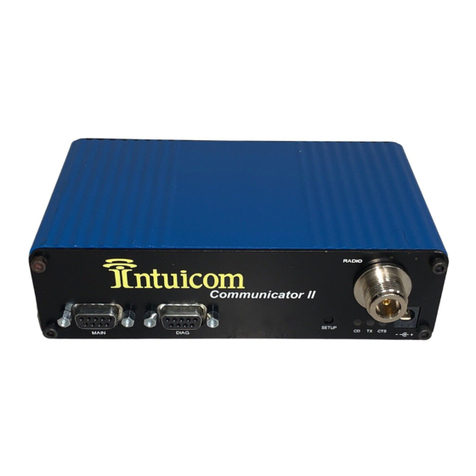
Intuicom DIO User manual

Intuicom, Inc.
1880 S Flatiron Court
Boulder, CO 80301
(303) 449-4330
www.intuicom.com
Intuicom®
DIO Transceiver
User Guide

DIO Transceiver User Guide
Revision 1.0a i © 2006 Intuicom Inc.
This manual is for use by purchasers and other authorized users of the IntuicomProducts. No
part of this document may be reproduced or transmitted in any form or by any means, electronic
or mechanical, or for any purpose without the express written permission of Intuicom Inc.
© 2000 - 2006 Intuicom Incorporated. All rights reserved.
Intuicom reserves the right to make changes to this manual without notice. Unless otherwise
agreed to in writing, Intuicom assumes no responsibility or liability for the use of this manual or
for the infringement of any copyright or other proprietary right and Intuicom shall deem nothing
contained in this manual a warranty or guarantee.
Intuicom, WiGate, Nav-Link, TargeTracker, Intuicom Communicator, Intuicom SmartGPS
Tracker/Surveyor, Intuicom SmartGPS Navigator, Intuicom Navigator II, Intuicom
Communicator II, DIO, and CommPro are trade names of Intuicom, Inc.
Other product names mentioned in this manual may be copyrights, trademarks, or registered
trademarks of their respective companies and are hereby acknowledged.

DIO Transceiver User Guide
Revision 1.0a ii © 2006 Intuicom Inc.
This product is licensed by The United States.
Diversion contrary to U.S. law is prohibited.
Shipment or re-export of this product outside of The
United States may require authorization by the U.S.
Bureau of Export Administration. Please contact
Intuicom, Inc. for assistance and further information.

DIO Transceiver User Guide
Revision 1.0a iii © 2006 Intuicom Inc.
Table of Contents
1Overview................................................................................................................................ 1
2Network Architectures......................................................................................................... 2
2.1 Point-to-Point ................................................................................................................. 2
2.2 Point-to-Multipoint......................................................................................................... 2
2.3 Utilizing a Repeater........................................................................................................ 3
3DIO Front Panel.................................................................................................................... 4
4Power Connection................................................................................................................. 5
5Programming Cable Connection......................................................................................... 6
6Inputs ..................................................................................................................................... 7
7Outputs................................................................................................................................... 9
8Antenna Connection........................................................................................................... 11
9Configuration ...................................................................................................................... 12
9.1 Configuration Process and Concepts ........................................................................... 12
9.1.1 Step 1: Create a radio configuration ..................................................................... 12
9.1.2 Step 2: Customizing the Configuration................................................................. 13
9.1.3 Step 3: Write Configuration to Radio ................................................................... 16
9.1.4 Step 4: Test Configuration/Network..................................................................... 16
9.2 Example Configuration................................................................................................. 17
10 Technical Specifications ................................................................................................. 18
11 FCC Notification............................................................................................................. 19
12 Warranty ......................................................................................................................... 20

DIO Transceiver User Guide
Revision 1.0a iv © 2006 Intuicom Inc.
Table of Figures
Figure 2-1: Point to Point Network Architecture............................................................................ 2
Figure 2-2: Point to Multipoint Network Architecture................................................................... 2
Figure 2-3: Point to Multipoint with Repeater................................................................................ 3
Figure 3-1: DIO Transceiver Front Panel ....................................................................................... 4
Figure 4-1: DIO Front Panel Power Jack........................................................................................ 5
Figure 4-2: DIO Power Plug ........................................................................................................... 5
Figure 5-1: Programming Cable Connectors .................................................................................. 6
Figure 6-1: Input Connection - Simple Contact Closure ................................................................ 7
Figure 6-2: Input Connection – Device .......................................................................................... 8
Figure 7-1: Output Connection - Relay .......................................................................................... 9
Figure 7-2: Output Connection - Device with Pullup Resistor..................................................... 10
Figure 7-3: Output Connection - Relay with Confirmation.......................................................... 10
Figure 8-1: Antenna Connection................................................................................................... 11
Figure 9-1: CommPro - Create new DIO Configuration .............................................................. 12
Figure 9-2: CommPro - Configuration Key Parameters............................................................... 13
Figure 9-3: CommPro - Configure Outputs.................................................................................. 15
Figure 9-4: CommPro - Example DIO Network Configuration ................................................... 17

Section 1: Overview
Revision 1.0a 1 © 2006 Intuicom Inc.
1 Overview
The Intuicom DIO wireless transceiver is a single product capable of being configured to
perform any role in a remote contact closure/discrete IO application. The DIO has eight inputs,
eight outputs, and can be configured as a base, remote, or remote/repeater. The DIO is capable
of operating bi-directionally (sending and receiving contact-closure signals) in both Point-to-
Point and Point-to-Multipoint architectures. The DIO features the ability to perform message
confirmation and notification of link integrity.
Combining bi-directional IO capabilities with individually addressable units, the DIO support an
almost limitless combination of configurations. Units can be sending and receiving IO signals
while repeating signals for other units – no dedicated repeater units required.
The DIO is available in spread-spectrum 900MHz and 2.4GHz license-free models. The DIO
can be configured using Intuicom CommPro™ software or through any terminal emulation
program – any available PC in the field can be used for configuration.
DIO applications include:
•Traffic Controller signaling: loop detectors, metering, counters, remote power and
signage.
•General SCADA: remote power control, event monitoring
•Security: remote event detection, remote alarm triggering
•Timing signal distribution

Section 2: Network Architectures
Revision 1.0a 2 © 2006 Intuicom Inc.
2 Network Architectures
2.1 Point-to-Point
The following diagram depicts a basic point-to-point architecture where the inputs of each
DIO are mapped (by configuration) to the outputs of the other. Point-to-point configurations
are the simplest to configure, and also result in the lowest end-to-end latency.
Figure 2-1: Point to Point Network Architecture
2.2 Point-to-Multipoint
The following diagram depicts a point-to-multipoint network architecture, where one master
DIO transceiver is linking with an unlimited number of remote or slave DIO transceivers.
While the master DIO transceiver is configured to listen to up to eight inputs (could be eight
from one remote, or one each from eight remotes, etc), the remote DIO transceivers can be
configure to listen to one or more of the master DIO’s inputs.
Figure 2-2: Point to Multipoint Network Architecture

Section 2: Network Architectures
Revision 1.0a 3 © 2006 Intuicom Inc.
2.3 Utilizing a Repeater
The following diagram depicts a point-to-multipoint network architecture with one DIO
transceiver utilizing the slave/repeater function allowing it to act as both a remote and a
repeater for other remotes simultaneously.
Figure 2-3: Point to Multipoint with Repeater

Section 3: DIO Front Panel
Revision 1.0a 4 © 2006 Intuicom Inc.
3 DIO Front Panel
All connectors and LED indicators for operation of the DIO Transceiver are available on the
front panel.
INPUTS
CD
DIO WIRELESS TRANSCEIVER
TX CTS
1 5
4 8
1 5
4 8 PWR
1 2 3 4 5 6 7 8 GND 1 2 3 4 5 6 7 8 GND
OUTPUTS
PROGRAM
Inputs Input state
LED
Indicators
Outputs Output
state LED
Indicators
Programminig
/Setup Serial
Port
Radio
state LED
Indicators
N-Type
Antenna
Connector
Power
Connector
Figure 3-1: DIO Transceiver Front Panel

Section 4: Power Connection
Revision 1.0a 5 © 2006 Intuicom Inc.
4 Power Connection
The DIO accepts an input voltage between 6 and 30 VDC. The mating power connector has a
locking ramp (Molex P/N: 39-01-2020). The DIO is supplied with a AC to DC adapter
(Intuicom P/N: FIP4-PSDIO-12). A DC cable is available as an optional accessory (Intuicom
P/N: FIP4-PGDIO-xx).
Care must be taken to ensure the correct supply voltage polarity. The DIO can be damaged if the
polarity is reversed –such damage is not covered under warranty.
The power connector’s polarity is depicted in the following diagrams:
Figure 4-1: DIO Front Panel Power Jack
++
-
-
Figure 4-2: DIO Power Plug

Section 5: Programming Cable Connection
Revision 1.0a 6 © 2006 Intuicom Inc.
5 Programming Cable Connection
A programming cable is required for configuration. A programming cable is included with each
pair of radios. The programming cable has one DB9 female end and one RJ12 end. The
programming cable pinout is as follows:
Figure 5-1: Programming Cable Connectors
RJ12 Plug Pins DB9 Female Pins
1 5
2 4
3 8
4 2
5 3
6 7
Table 5-1: Programming Cable Pinout
Replacement programming cables can be ordered from Intuicom (Intuicom P/N: FIP4-PRGDIO-
R).
For setup, the programming cable must be attached to the RJ12 jack on the front panel of the
DIO as well as connected to a DB9 male serial connection on a PC.

Section 6: Inputs
Revision 1.0a 7 © 2006 Intuicom Inc.
6 Inputs
The eight inputs on the DIO are ground activated and accept an input voltage range from 0 to 30
VDC. The detachable terminal block connector has nine positions: one position for each input,
and one position for a common ground to the connected device(s). Inputs are activated by
bringing the input to ground. This can be accomplished through a simple switch between the
input and the common ground terminal. Inputs can also be activated by connecting them to
another device’s open-collector (or compatible) output – and connecting a common ground
between the two devices. See the example wiring diagrams.
Figure 6-1: Input Connection - Simple Contact Closure

Section 6: Inputs
Revision 1.0a 8 © 2006 Intuicom Inc.
Figure 6-2: Input Connection – Device

Section 7: Outputs
Revision 1.0a 9 © 2006 Intuicom Inc.
7 Outputs
The DIO has eight mosfet open-drain outputs. mostfet open-drain outputs work like open-
collector outputs, and can be thought of as low-current DC switches. Each output can sink up to
550ma, with the total across all outputs not to exceed 2A. The detachable nine position Phoenix
terminal block connector has one position for each output and one position for a common ground
connection to the connected device(s).
The DIOs outputs can be utilized in a number of ways. The following two examples depict
different ways to interface the DIO outputs.
Figure 7-1: Output Connection - Relay

Section 7: Outputs
Revision 1.0a 10 © 2006 Intuicom Inc.
Figure 7-2: Output Connection - Device with Pullup Resistor
Figure 7-3: Output Connection - Relay with Confirmation

Section 8: Antenna Connection
Revision 1.0a 11 © 2006 Intuicom Inc.
8 Antenna Connection
The DIO has an industry-standard N-Type female antenna connector on the front panel. Connect
an antenna appropriate for the unit’s frequency band (either 900MHz or 2.4GHz) and for the
application (omni, yagi, etc) prior to operation.
•Be sure to use high-quality low-loss 50Ωcoax cable (LMR400 or similar) for the
transmission line between the antenna connector and the antenna.
•Ensure connector ends are correctly installed on the coax transmission line. Poorly made
connections can appear good but severely degrade performance.
•Depending upon the installation location, an in-line lighting arrestor may be necessary to
enhance safety and protect equipment.
•Be sure to adequately waterproof transmission line connections. Moisture present in
connections may degrade performance and damage equipment.
Figure 8-1: Antenna Connection

Section 9: Configuration
Revision 1.0a 12 © 2006 Intuicom Inc.
9 Configuration
The DIO Transceiver is configured using Intuicom CommPro software. CommPro will allow the
user to read, modify, and save a unit’s configuration, as well as export a PDF copy for archival
reference and documentation.
To be able to use CommPro to configure a DIO unit, be sure:
•CommPro is installed
•A serial port (COM port) is available
•A programming cable is connected between the COM port and the DIO unit’s
programming port
•Power is applied to the unit.
9.1 Configuration Process and Concepts
9.1.1 Step 1: Create a radio configuration
Start CommPro and select the Configuration application. Create a new configuration by
selecting New…Config…DIO Transceiver (all Models) from the menu.
Figure 9-1: CommPro - Create new DIO Configuration

Section 9: Configuration
Revision 1.0a 13 © 2006 Intuicom Inc.
A default DIO configuration will appear in the configuration area of the screen. At this
point you may choose to read the DIO’s current configuration, by clicking on the “READ
CONFIG” button on the toolbar, or simply modify the on screen defaults to suit.
Figure 9-2: CommPro - Configuration Key Parameters
9.1.2 Step 2: Customizing the Configuration
The DIO configuration area has two tabs: Key Parameters, and Outputs. Start by
modifying the parameters on the Key Parameters tab:
Unit ID
Each DIO unit in a given network should have a unique Unit ID. One (and only one)
units is designated the Master DIO in the network, this unit must be assigned ID “0”.
Unit IDs are used later to configure the DIO’s outputs.
Frequency Key
All DIO units in a given network must have the same Frequency Key. DIO networks
nearby each other should have different Frequency Keys to minimize interference. The
actual value for the Frequency Key is not important, only that every unit in a network has
the same value. It is recommended to change from the default value of “6”.
Network ID
Like the Frequency Key, all units in a given network must have the same Network ID to
be able to communicate. A network ID can be any value from 1 to 4095 except 255.

Section 9: Configuration
Revision 1.0a 14 © 2006 Intuicom Inc.
Pick a value for Network ID and assign it to every unit that will participate in the same
network.
Inputs
The Inputs parameter controls whether this unit’s inputs are enabled or disabled.
Slave Repeater Mode
A given unit (except for the Master) can be a repeater while operating as a remote or
slave unit. Note that this mode is not compatible with Low Latency Mode or Low
Current Mode.
Low Latency Mode
This mode is designed to minimize state transition time latency from one input to a given
output. This mode is intended to be used when units are operated in a point-to-point
configuration. This mode is not compatible with Slave/Repeater Mode or Long Range
Mode.
Low Current Mode
Low Current Mode can conserve power by disabling the Input and Output status LEDs.
Long Range (Extended Performance RF) Mode
Long Range Mode can improve RF performance in noisy RF environments at the cost of
latency. All radios in a given network must be configured the same, either enabling or
disabling this mode.
Diagnostics Data Stream Enabled
The option allows CommPro’s Diagnostics module to connect and display real-time
diagnostics for a network. This mode should only be enabled while operating diagnostics
and should be disabled again after diagnostics analysis is complete. This mode is only
valid when enabled (and should only be enabled) on the MASTER radio of a network.

Section 9: Configuration
Revision 1.0a 15 © 2006 Intuicom Inc.
Figure 9-3: CommPro - Configure Outputs
The Outputs tab of the configuration area has a table or parameters for configuring the
DIO’s Outputs. There is one row or parameters for each Output:
Remote Unit ID
This specifies which remote DIO unit this output number will follow, or “listen to.” This
can be any valid ID in the network, but is cannot be THIS unit’s ID.
Remote Unit Input #
This parameter configures which specific Input Number (1-8) on the Remote Unit’s
(configured with Remote Unit ID) Inputs to follow or “listen to.”
Failsafe Timeout (ms)
Failsafe Timeout specifies an amount of time in milliseconds to wait without hearing
from the Remote Unit for this Output before driving the Output state specified by the
next parameter, Failsafe State. The default timeout is 10s or 10000ms.
Failsafe State
There are four options for Failsafe State, the state that the output is driven to when the
Failsafe Timeout time is exceeded: LAST, ON, OFF, or FLASH. LAST keeps the
current state the same after the Failsafe Timeout time is exceeded. ON, drives the output
into the ON or conductive state, OFF drives the output to the OFF or non-conductive
state, and FLASH, alternates between ON and OFF at ~ 1Hz.
Table of contents
Other Intuicom Transceiver manuals