SGM G-7 SPOT User manual
USERMANUAL
G7 SPOT
Product Version 1 | Document Revision E | Released 2023-01-11
2Product Version 1.0 | Revision E | Released 2023-01-11
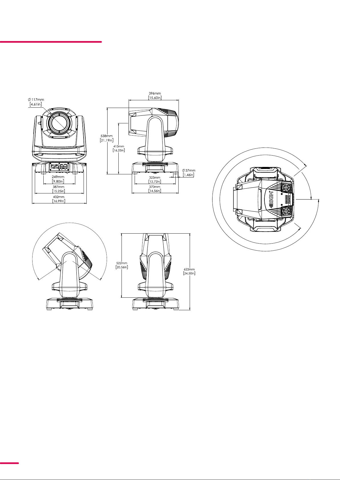
G7 SPOT DIMENSIONS
G7 SPOT STANDARD VERSION
All dimensions in millimeters and inches. Drawing not to scale
This manual covers installation, use, and maintenance of the SGM G-7 Spot. A digital version is available at
www.sgmlight.com or upon request via [email protected]. The information in this document is subject to
change without notice. SGM and all affiliated companies disclaim liability for any injury, damage, direct or
indirect loss, consequential or economic loss, or any other loss occasioned by the use of, inability to use, or
reliance on the information contained in this manual. The SGM logo, the SGM name, and all other trademarks
in this document perwtaining to SGM services or SGM products are trademarks owned or licensed by SGM, its
affiliates, and subsidiaries. This edition applies to firmware version 2.23 or later.
English edition © 2022 SGM Light A/S®.
240°
310°
310°

3Product Version 1.0 | Revision E | Released 2023-01-11
G7 SPOT POI VERSION
All dimensions in millimeters and inches. Drawing not to scale

4Product Version 1.0 | Revision E | Released 2023-01-11
CONTENT
2 G-7 SPOT DIMENSIONS
2 G-7 Spot Standard version
3 G-7 Spot POI version
6 SAFETY INFORMATION
7 BEFORE INSTALLING THIS PRODUCT
8 INSTALLATION STANDARD FIXTURE
8 Parts identication and terminology
9 Unpacking
9 Application considerations
9 Transport handling
10 Rigging
11 Rigging process using SGM Omega bracket
12 Power requirements
13 Connecting power
13 Connecting data
14 Mechanical Tolerances and Recommended Use in Low Ambient Temperatures
15 INSTALLATION POI FIXTURE
15 Identication and terminology
16 Unpacking
16 Application considerations
16 Connecting temporary Power
16 Conguration
17 Connecting temporary signal
17 Settings and Fixture Defaults
18 Wireless Data Connection
18 LED Indicator
19 Mounting
21 Mechanical Tolerances and Recommended Use in Low Ambient Temperatures
22 Permanently Connecting Power & Data
23 USER INTERFACE
23 Wireless Indicator(A)
23 Fixture name(B)
23 Next DMX Address (C)
23 DMX Address (D)
23 DMX Mode (E)
23 Using the keyboard (F)
24 CONNECTING TO A DMX CONTROL DEVICE
24 Connecting to a DMX control device
24 Connecting a wireless transmitter

5Product Version 1.0 | Revision E | Released 2023-01-11
CONTENT
24 Disconnecting a wireless transmitter
24 Signal priority
25 CONFIGURING THE DEVICE FOR DMX CONTROL
25 About DMX
25 DMX Start address
25 Setting the DMX address
25 DMX modes
26 CONTROL MENU
29 RDM
29 Supported RDM functions
29 Sensors
30 FACTORY DEFAULT
30 FIXTURE PROPERTIES
30 CMY color mixing
31 Eect wheel
31 Two independent gobo wheels
31 High-precision pan and tilt
31 Strobe eect
31 Prism
31 Internal frost
31 Flipping the OLED display
32 GOBO WHEELS
32 Identication of gobo wheel
33 GOBO REPLACEMENT
35 POLYTETRAFLUOROETHYLENE (PTFE) MEMBRANE
36 ACCESSORIES
36 Attaching the Top Hat
37 TROUBLESHOOTING
38 MAINTENANCE
38 SGM Vacuum Test kit
39 Firmware updates
40 Cleaning
41 FIXTURES AND ACCESSORIES
41 Ordering information
41 G-7 spot accessories
41 SUPPORT HOTLINE
42 APPROVALS AND CERTIFICATIONS
43 USER NOTES
6Product Version 1.0 | Revision E | Released 2023-01-11
SAFETY INFORMATION
SGM fixtures are intended for professional use only. They are not suitable for household use.
Les fixtures SGM sont impropre à l’usage domestique. Uniquement à usage professionnel.
This product must be installed in accordance with the applicable installation code by a person
familiar with the construction and operation of the product and the hazards involved.
Ce produit doit être installé selon le code d’installation pertinent, par une personne qui connaît
bien le produit et son fonctionnement ainsi que les risques inhérent.
DANGER! RISK OF ELECTRIC SHOCK DO NOT OPEN THE DEVICE!
• Always power off/unplug the fixture before removing covers or dismantling the product.
• Ensure that the mains power is cut off when wiring the device to the AC mains supply.
• Ensure that the device is electrically connected to earth (ground).
• Do not apply power if the device or mains cable is in any way damaged.
• Do not immerse the fixture in water or liquid.
WARNING! TAKE MEASURES TO PREVENT BURNS AND FIRE!
• Install in a location that prevents accidental contact with the device.
• Install only in a well-ventilated space.
• Install at least 0.3 m (12 in.) away from objects to be illuminated.
• Install only in accordance with applicable building codes.
• Ensure a minimum clearance of 0.3 m (12 in.) around the cooling fans
• Do not paint, cover, or modify the device, and do not filter or mask the light.
• Keep all flammable materials well away from the device.
ALLOW THE DEVICE TO COOL FOR 15 MINUTES AFTER OPERATION BEFORE TOUCHING IT
CAUTION: EXTERIOR SURFACE TEMPERATURE AFTER 5 MIN. OPERATION = 42°C 108°F.
STEADY STATE = 48°C 118°F.
WARNING! TAKE MEASURES TO PREVENT PERSONAL INJURY. DO NOT
LOOK DIRECTLY AT THE LIGHT SOURCE FROM CLOSE RANGE.
• Take precautions when working at height to prevent injury due to falls.
• For Permanent Outdoor Installations (POI), ensure that the fixture is securely fastened
to a load-bearing surface with suitable corrosion-resistant hardware.
• For a temporary installation with clamps, ensure that the quarter-turn fasteners are
turned fully and secured with a suitable safety cable. The standard safety wire cable
must be approved for a safe working load (SWL) of 10 times the weight of the fixture,
made of a grade AISI 316 steel, and it must have a minimum gauge of 4 mm.
• For elevated installations, secure the fixture with suitable safety cables, and always com-
ply with relevant load dimensioning, safety standards, and requirements.
WARNING! READ THE FOLLOWING SAFETY PRECAUTIONS CAREFULLY BE-
FORE UNPACKING, INSTALLING, POWERING OR OPERATING THE DEVICE.

7Product Version 1.0 | Revision E | Released 2023-01-11
BEFORE INSTALLING THIS PRODUCT
Please visit the SGM official website at www.sgmlight.com for the latest version of this user
manual/ safety information leaflet. Due to continuous improvements, the instructions may
change without notice. SGM always recommends the latest available firmware version from
www.sgmlight.com.
EXTERNAL CLEANING AND VISUAL INSPECTION OF THE FIXTURE
All users of the SGM fixtures should regularly clean those parts of the fixture directly exposed to
the elements, such as the external housing and front lenses. Additionally, all owners of the SGM
fixtures must periodically check the external housing of the fixture for structural breaks, deteri-
oration, cracked lenses, or loose screws. To ensure proper operation, but also to prevent the risk
of potential accidents, do not use the fixture if the lens, housing, or power cables are damaged.
If parts of the fixture appear to be missing, cease use immediately and contact SGM support.
WIRING AND CONDUIT/ CONTAINMENT
SGM fixtures supplied with power and data cable leads are not intended for installation in
permanently installed conduit or containment. When installing the fixtures in a permanent
installation, ensure cable leads are installed as a service loop to an appropriately rated junction
box using suitable cable strain reliefs/glands. All installed fixtures must be securely mounted,
and service loop appropriately protected for installation location. All electrical wiring and
connections should be completed by a qualified electrician.
SAFETY PRECAUTIONS
When using electrical equipment, basic safety precautions should always be followed including
the following:
• Do not mount near gas or electric heaters.
• Permanently installed equipment should be mounted in locations and at heights where
it will not be readily subjected to tampering by unauthorized personnel.
• The use of accessory equipment not recommended by the manufacturer may cause an
unsafe condition.
• Do not use this equipment for other than intended use.
• Refer service to qualified personnel or authorized service centers.
• Do not look directly into the beam for long periods of time, when the fixture is on.
• The fixture shall, under no circumstance, be covered with insulating material of any kind.
READ AND FOLLOW ALL SAFETY INSTRUCTIONS.

8Product Version 1.0 | Revision E | Released 2023-01-11
INSTALLATION STANDARD FIXTURE
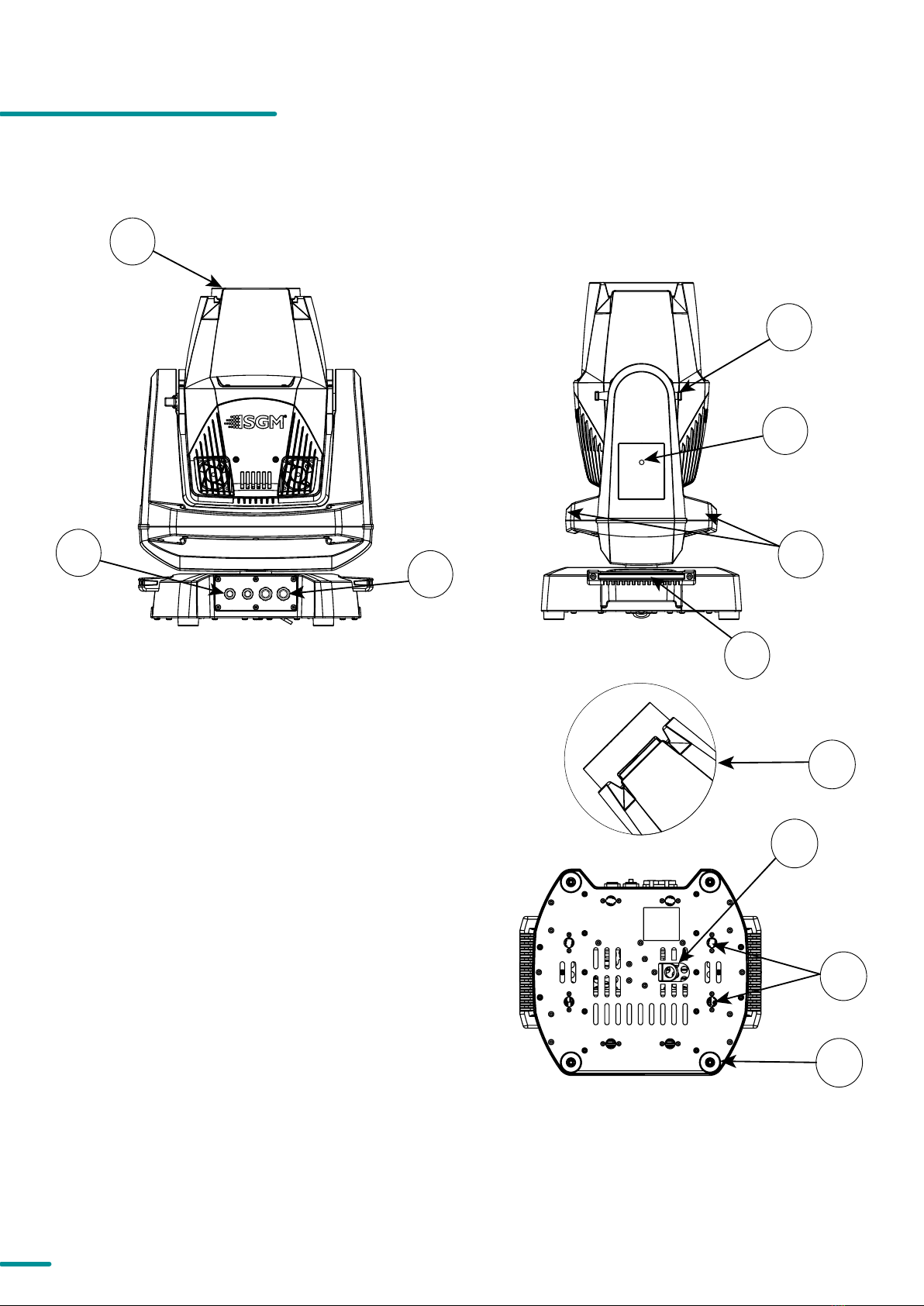
PARTS IDENTIFICATION AND TERMINOLOGY
Illustrations might vary from received products. This is subject to change without notice.
I
F
D
J
A
G
B
K
H
E
A: Front lens
B: DMX in and out
C: Power in and out
D: Tilt lock/unlock
E: Display and control panel POI n/a
F: Yoke handles
G: Base handle (x2)
H: G-7 with Tophat (accessory)
I: Safety wire attachment point
J: Holes for omega bracket (x8)
K: Rubber feet (x4)
C

9Product Version 1.0 | Revision E | Released 2023-01-11
UNPACKING
Unpack the device and inspect it to ensure that it has not been damaged during transport.
The G-7 Spot /Standard version only/ is shipped with:
• Power cable with power input connector, 2 m (78 in.).
• Two omega brackets with 1/4-turn fasteners.
• Safety information leaflet.
APPLICATION CONSIDERATIONS
The fixture is IP66-rated and designed for both indoor and outdoor events. This means that it is protected from:
• Dust, to the degree that dust cannot enter the device in sufficient quantities as to interfere with its operation.
• Water jets from any direction.
When selecting a location for the device, ensure that:
• It is situated away from public thoroughfares and protected from contact with people.
• It is not immersed in water.
• It has adequate ventilation.
• Will not be focused with the glass lenses towards the sun for extended periods of time.
When using the fixture with a DMX controller, ensure that:
• The DMX out of the last fixture is terminated with a 120 ohm resistor between pin 2 and 3, according to the
RS485 standard.
• The DMX out is properly sealed by mounting the protection cap in accordance with the ingress protection
(IP) requirements.
• A maximum of 32 fixtures can be connected to the same DMX link.
The DMX connection out of the last fixture in a chain is properly sealed, in accordance with the ingress protection
(IP) requirements.
The DMX out of the last fixture is terminated with a 120 Ohm resistor between pin 2 and 3 (as per RS485 standards).
TRANSPORT HANDLING
Always use the supplied packaging or suitable flight case for transportation and storage.
Release the tilt lock when transporting the fixture. Leaving the tilt lock blocked may cause damage to the fixture.
Never carry the fixture by connected cables or wires; use the handles.

10 Product Version 1.0 | Revision E | Released 2023-01-11
Figure 2: G-7 Spot base with Omega brackets
A: Omega Bracket
B: 1/4-turn locking points (vertical view)
C: Omega Brackets attached to the 1/4-turn
locking points (horizontal view) A
B
C
All SGM fixtures have locking points at the base for installation and
rigging. The distance between the points from centre to centre is
always 106 mm (Fig. 1). The base of the standard G-7 Spot includes
1/4-turn fastener cam locks to mount the omega brackets.
POI versions come with M-10 captive nuts for M-10 screws. The G-7
Spot may be installed in any orientation, with or without base, on
the ceiling or on a wall surface.
Always use the supplied omega brackets and lock with 1/4-turn
fasteners.
PLEASE NOTE! 14TURN FASTENERS ARE ONLY LOCKED WHEN TURNED FULLY CLOCKWISE.
DEPENDING ON THE STRUCTURE, PLEASE USE APPROPRIATE AND SECURE METHODS FOR MOUNTING THE
OMEGA BRACKET.
106 mm
[ 4,2in ]
Ø 18 mm
[ 0,7in ]
Figure 1: SGM Locking points
RIGGING
WARNING! ALWAYS USE MIN. 2 OMEGA BRACKETS WHEN RIGGING THE FIXTURE.
11 Product Version 1.0 | Revision E | Released 2023-01-11
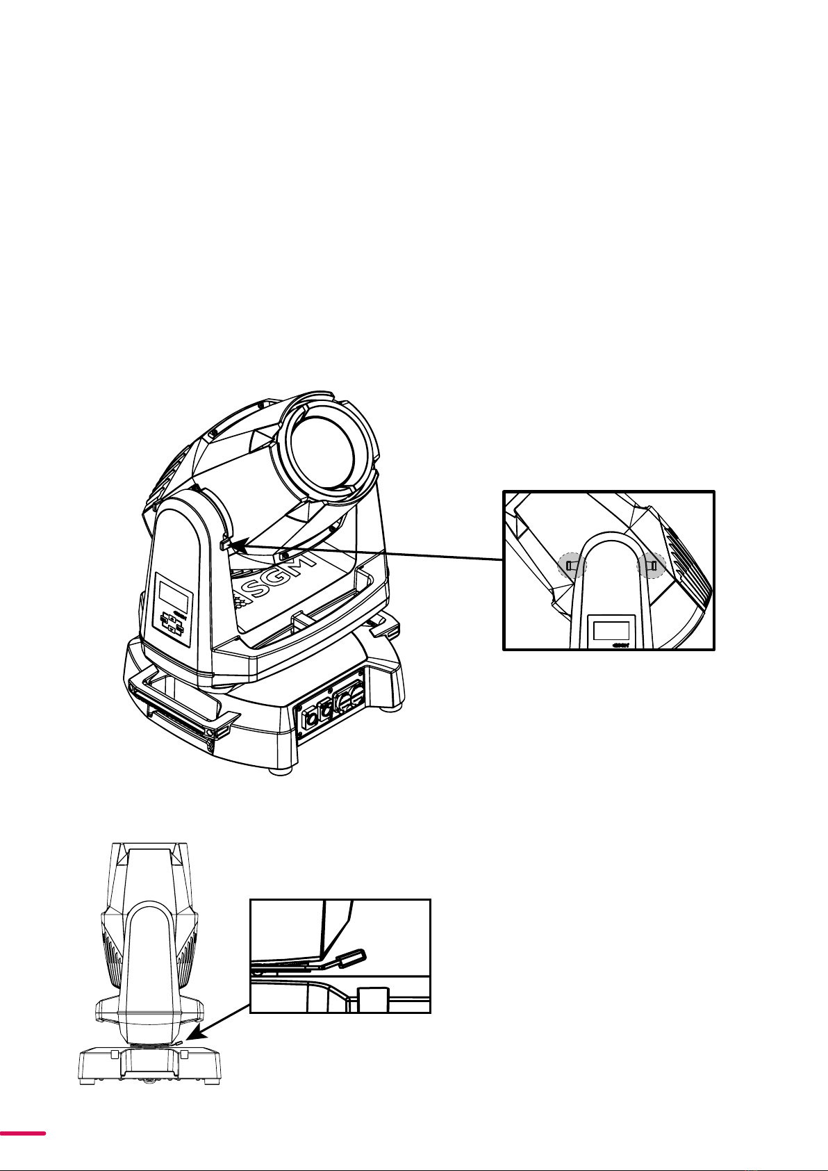
Figure 3: G-7 Spot Tilt Lock
Figure 4: G-7 Spot Pan Lock
RIGGING PROCESS USING SGM OMEGA BRACKET
Start the rigging process by blocking the lower working area, and make sure the work is performed from a stable
platform.
1. Select a clamp / bracket is undamaged and can bear at least 10 times the weight of the fixture. Check that
the structure can bear at least 10 times the weight of all installed fixtures, lamps, cables etc.
2. Bolt the clamp / bracket securely to the omega bracket with a M12 / ½" bolt (min. grade 8.8 C5M) and a lock
nut.
3. Align an Omega bracket with two 1/4-turns in the G-7 Spot base. Insert the fasteners into the G-7 Spot base
and turn both levers a full 1/4-turn clockwise to lock. Install the second Omega bracket.
4.Working from a stable platform, hang the fixture on a truss, or other structure. Note the position of the base.
Tighten the clamps.
5. Install a safety wire that can bear at least 10 times the weight of the fixture. The safety wire attachment point
is designed to fit a carabiner.
6. Check if the tilt lock is released. If not, push the slide button shown in the figure 3 to the right to release the
tilt lock.
Tilt lock - slide button
7. Check if the pan lock is released. If not, slide the
pan lock shown in the figure 4 to the right to
release the pan lock.
8. Verify that there are no combustible materials
or surfaces within 300 mm (12 in.) of the fixture.
9. Check that there is no possibility of head or
yoke colliding with other fixtures.

12 Product Version 1.0 | Revision E | Released 2023-01-11
WARNING! ALWAYS SECURE AN ELEVATED G-7 SPOT WITH A SAFETY WIRE
Fasten a safety wire (not shown) between the load-bearing support structure and the safety wire attachment point
on the device. The safety cable (not included in the package) must:
• Bear at least 10 times the weight of the device (SWL).
• Have a minimum gauge of 4 mm.
• Have a maximum length (free fall) = 300 mm (12 in.).
CAUTION!
ALWAYS USE A SAFETY WIRE OF A GRADE AISI 316 STEEL.
MAKE SURE THE SLACK OF THE SAFETY WIRE IS AT A MINIMUM.
NEVER USE THE YOKE OR THE CARRYING HANDLES FOR SECONDARY ATTACHMENT.
MAKE SURE THE SLACK OF THE SAFETY WIRE IS AT A MINIMUM.
NEVER USE THE YOKE OR CARRYING HANDLES FOR SECONDARY ATTACHMENT.
Figure 5: Safety Wire attachment point
The G-7 Spot can operate on any 100–240 V, 50/ 60Hz AC mains power supply.
The maximum power consumption is 480 W.
Connect the fixture to AC power by using the supplied power cable (fig.6)
with IP connector or similar with a maximum of 20 A, to ensure the correct
ingress protection (IP rating).
The fixture must be grounded/ earthed and able to be isolated from AC
power. The AC power supply must incorporate a fuse or circuit breaker for
fault protection.
POWER REQUIREMENTS
The fixture must be grounded/
earthed and be able to be isolated
from AC power. The AC power
supply must incorporate a fuse or
curcuit breaker for fault protection.
Color
Black
White
green/yellow
Conductor
live
neutral
ground (earth)
Symbol
or
L
N
Wire
Figure 6: Power cable

13 Product Version 1.0 | Revision E | Released 2023-01-11
Max. 32 units/DMX line
1 2 xx
100 - 277V AC
50-60 Hz
500 W
100 - 277V AC
50-60 Hz
500 W
100 - 277V AC
50-60 Hz
500 W
DMX Termination
on last fixture DMX ou
t
DATA
GND
DATA -
DATA +
120 Ohm +/- 5%
Max. 6 units/16 A circuit
CONNECTING POWER
The power cable color coding is given in figure 7:
• Connect the black wire to live.
• Connect the white wire to neutral.
• Connect the green / yellow wire to ground (earth).
For an outdoor installation, the mains cable must be fitted with a grounded connector intended for exterior use.
After connecting the G-7 Spot to power, run the on-board test by selecting TEST → AUTOMATED TEST in the menu to
ensure that the fixture is functioning correctly.
CAUTION!
DO NOT CONNECT THE FIXTURE TO AN ELECTRICAL DIMMER SYSTEM AS DOING SO MAY
CAUSE DAMAGE.
CONNECTING DATA
The G-7 Spot is controllable by a DMX control device, and can be connected by either a DMX cable or via the fixture’s
built-in CRMX wireless receiver system. This system is compatible with Lumenradio 2.4GHz systems.
When using a cabled DMX system, connect the DMX-In cable to the input connector and DMX-Out cable to the
output, both on the rear of the fixture’s base (chassis mounted male and female 5-pin XLR plugs). For outdoor
installations, use only IP-rated XLR connectors suitable for outdoor use. Terminate the DMX out cable of the last
fixture in the data link with a 120 ohm DMX termination.
Note that SGM fixtures provide a passive DMX Thru signal as DMX Out, instead of an active output signal.
The fixture must be grounded/
earthed and be able to be isolated
from AC power. The AC power
supply must incorporate a fuse or
curcuit breaker for fault protection.
Color
Black
White
green/yellow
Conductor
live
neutral
ground (earth)
Symbol
or
L
N
Wire
Figure 7: Connecting AC Power
Figure 8: Connecting DMX in G-7 Spot

14 Product Version 1.0 | Revision E | Released 2023-01-11
MECHANICAL TOLERANCES AND RECOMMENDED USE IN LOW AMBIENT TEMPERA
TURES
Ambient temperature range for storage, start-up, and operation of G-7 Spot and G-7 Spot POI moving heads is
described at www.sgmlight.com.
All lighting fixtures have mechanical tolerances which can introduce unexpected results when in extreme tempera-
tures. To minimize these undesirable effects in extreme cold, from firmware 1.31 on, the G-7 Spot (both in POI and
non-POI versions) includes a “Heat Up mode” feature accessible via the “Function” DMX channel (DMX chart avail-
able at www.sgmlight.com). This functionality pre-conditions the mechanical systems of the unit during low ambi-
ent temperature periods, without creating a visual impact in the illuminated area. When the user activates the “Heat
Up mode” the fixture warms up by operating the light source at 30% output as well as adjusting other settings. The
CMY flags, CTO and iris functions are also used to block as much light as possible. Pan / tilt movement or gobo
wheels are not affected and will still respond to DMX parameters.
In temperatures below -20º C (-4º F) degrees, main features such as pan and tilt function correctly, while the preci-
sion mechanical features such as gobo indexing may not perform at their maximum accuracy even when using the
“Heat Up mode”. To use the precision mechanical features at their best, when in ambient temperatures below -20º C
(-4º F), a full-output warm-up procedure is advised. See below for more details.
IP66 -Standard version Recommended Operation
The reliability of the main features in the G-7 Spot will not be compromised by the presence of low temperatures as
long as the values indicated in the specifications are respected. To achieve the best performance of the precision
mechanical systems, SGM recommends warming up the internal parts by using the light source at 100% output
before operating the programmed scenes when the fixture is to be used in ambient temperatures below 0º C (32º
F). The required time to warm up the mechanical systems of the unit and for them to function accurately depends
entirely on the ambient conditions. A test on location is advised.
SGM recommends avoiding tight mapping in multiple fixtures such as vertical or horizontal alignment of gobo
projection in extreme conditions. Continued use of these moving parts can sporadically cause deviations from
expected performance. Before attempting repair, it is recommended to remotely reset the fixture via the “Function”
DMX channel (see DMX charts at www.sgmlight.com) and / or power-cycle the fixture. In non-POI devices, it is also
possible to calibrate these functionalities manually via the integrated OLED display.
PLEASE NOTE! THE PROTECTIVE CAPS MUST BE SECURELY MOUNTED ON ANY UNUSED DMX CONNECTORS IN
ORDER TO MAINTAIN THE IP RATING.
PLEASE NOTE! IF USING A WIRELESS DMX SYSTEM, REMEMBER TO USE THE PROTECTIVE CAPS IN ANY UNUSED
DMX CONNECTOR IN ORDER TO MAINTAIN THE FIXTURE’S IP RATING.
CONNECTING A WIRELESS TRANSMITTER
The G-7 Spot is designed to look for wireless transmitters in ‘connect’ state when this option is enabled. The fixture
comes tested for wireless functionality from the factory, therefore the beginning of the pairing process is disconnect
from the factory wireless DMX transceiver.
To connect the G-7 Spot to a wireless transmitter:
1. Log off the currently paired wireless transmitter. Go to SETTINGS → WIRELESS DMX → LOG OFF in the menu.
Fixture confirms logged off.
2. Press the connect button on the wireless transmitter.
3. Confirm that the fixture has paired with the wireless transmitter.
PLEASE NOTE! FOR POI VERSIONS, REFER TO "WIRELESS DATA CONNECTION" ON PAGE 18
The G-7 Spot can be paired to an active wireless transmitter simultaneously when connected to a cabled DMX. The
fixture will prioritize cabled DMX over wireless DMX.
The active input type is displayed under the wireless signal strength indicator. The signal strength can be also
checked via RDM data by using an external RDM device.
Product Version 1.0 | Revision E | Released 2023-01-11
15
INSTALLATION POI FIXTURE
IDENTIFICATION AND TERMINOLOGY
Illustrations might vary from received products. This is subject to change without notice.
A: Front lens
B: DMX in and out
C: Power in and out
D: Tilt lock/unlock
E: Led Indicator
F: Yoke handles
G: Base handle (x2) (POI n/a)
H: G-7 with Tophat (accessory)
I: Safety wire attachment point
J: Holes for omega bracket (x8)
K: Rubber feet (x4)
E
I
J
A
F
B
K
H
D
G
C

16 Product Version 1.0 | Revision E | Released 2023-01-11
PLEASE NOTE! POI FIXTURES SHOULD BE PRESET WITH ANY CUSTOM PROGRAMMING BEFORE INSTALLATION.
ALTHOUGH MOST FUNCTIONS ARE POSSIBLE TO BE SET VIA RDM ONCE MOUNTED IN POSITION, IT IS EASIER
TO DO CONFIGURATION AND ANY TROUBLESHOOTING BEFORE MOUNTING IS COMPLETE.
UNPACKING
Unpack the device and inspect it to ensure that it has not been damaged during transport.
The G-7 Spot is shipped with:
• Two POI omega brackets suited for M-10 holes.
• Safety information leaflet.
APPLICATION CONSIDERATIONS
The fixture is IP66-rated and designed for both indoor and outdoor events. This means that it is protected from:
• Dust, to the degree that dust cannot enter the device in sufficient quantities, as to interfere with its opera-
tion.
• High pressure water jets from any direction.
When selecting a location for the device, ensure that:
• It is situated away from public thoroughfares and protected from contact with people.
• It is not immersed in water.
• It has adequate ventilation.
When using the fixture with a DMX controller, ensure that:
• According to RS485 standard, the DMX Out of the last fixture should be terminated with a 120 ohm resistor
between pin 2 and 3.
• If the resistor is not installed, make sure that the DMX Out is properly sealed by mounting the protection cap,
in accordance with the ingress protection (IP) requirements.
• A maximum of 32 fixtures can be connected to the same DMX link.
CONNECTING TEMPORARY POWER
Connect to AC power using the supplied 8mm cable (the larger of the two permanently wired cables). The fixture
must be grounded/earthed. The AC power supply must incorporate a fuse or circuit breaker for fault protection. For
temporary programming, a plug or terminals can be used.The power cable color coding is shownin fig. 9:
• Connect the black wire to live
• Connect the white wire to neutral
• Connect the green/yellow wire to ground (earth)
The fixture must be grounded/
earthed and be able to be isolated
from AC power. The AC power
supply must incorporate a fuse or
curcuit breaker for fault protection.
Color
Black
White
green/yellow
Conductor
live
neutral
ground (earth)
Symbol
or
L
N
Wire
Figure 9 : Connecting AC Power
CONFIGURATION
The G-7 Spot POI does not include a display, and is configured through RDM (Remote Device Management). See
"RDM" on page 29 for more information.
In G-7 Spot POI, the DMX address and DMX mode can only be set through RDM. When addressing through USB
powered DMX/ RDM devices, ensure DMX link is terminated, and keep the cable as short as possible.
DMX modes for POI are the same as the G-7 Spot standard. Visit www.sgmlight.com to see all DMX charts available
PLEASE NOTE! REMOTE DEVICE MANAGEMENT RDM REQUIRES A CORRECT DMX CABLED INSTALLATION AND
TERMINATION. WHEN SETTING ADDRESSES THROUGH RDM AND USING USB DONGLES, DISABLE USB SELEC
TIVE SUSPEND TO ENSURE A PROPER VOLTAGE TO THE DMX LINK. IF ANY LAG OR TROUBLE OCCURS WHEN
ADDRESSING, DECREASE THE CABLE LENGTH RANGE TO <12 M. AND ONLY ADDRESS ONE FIXTURE AT A TIME.
17 Product Version 1.0 | Revision E | Released 2023-01-11
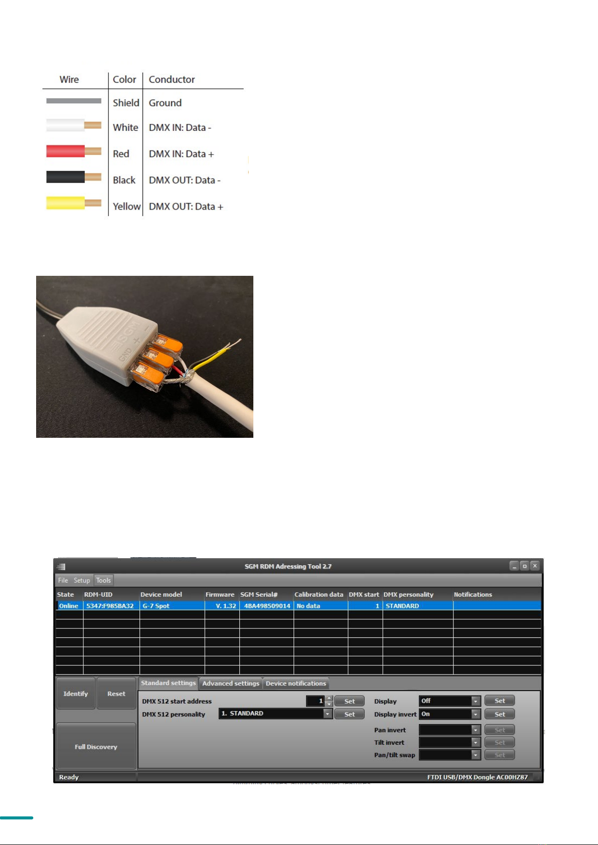
CONNECTING TEMPORARY SIGNAL
The fixture is compatible with DMX512 (ANSI E1.11 – 2008)
only. It can be connected using either the SGM POI
up-loader cable, or via the fixture’s built-in CRMX wireless
receiver system.
STEP 1: Download and install the SGM RDM Addressing
tool.
< https://sgmlight.com/products/rdm-addressing-tool >
STEP 2: Connect the bare end data cable to the POI
Up-loader cable for POI fixtures.
STEP 3: Connect the USB up-loader cable for POI fixtures
to a computer with a USB Type-A port.
STEP 4: Launch SGM RDM Addressing Tool. Click Full
Discovery and look for the green light to illuminate on the
fixture. Configure all settings as needed. See Settings and
Fixture Defaults for more configuration instructions.
Step 5 Disconnect up-loader cable from computer, then
disconnect up-loader cable from fixture.
Repeat Steps 2-5 for more fixtures. Multiple fixtures can be
addressed and configured. Contact your SGM representa-
tive for more information on multiple fixture addressing.
Please NOTE! At a minimum, all fixtures will need to be
given a DMX address and DMX personality in order to
patch and program on a controller. Refer to manuals for
more details.
Figure 10: Data wiring guide for setup
Figure 11: Connecting data to USB up-loader cable for
POI fixtures
SETTINGS AND FIXTURE DEFAULTS
All configuration of POI fixtures is done through the SGM Addressing Tool. The SGM Addressing Tool is a Windows®
based program designed to allow the user to configure the fixture through the RDM protocol. All settings on a
standard fixture are available on a POI fixture. But on POI, these settings are changed through the Addressing Tool.
Figure 12: SGM Addressing tool
18 Product Version 1.0 | Revision E | Released 2023-01-11
In POI versions with wireless, it is necessary to pair the fixture
with a new transmitter (by default, the fixture is linked to the
SGM factory transmitter).
In order to do so, make sure the fixture is powered on before
taking the following steps:
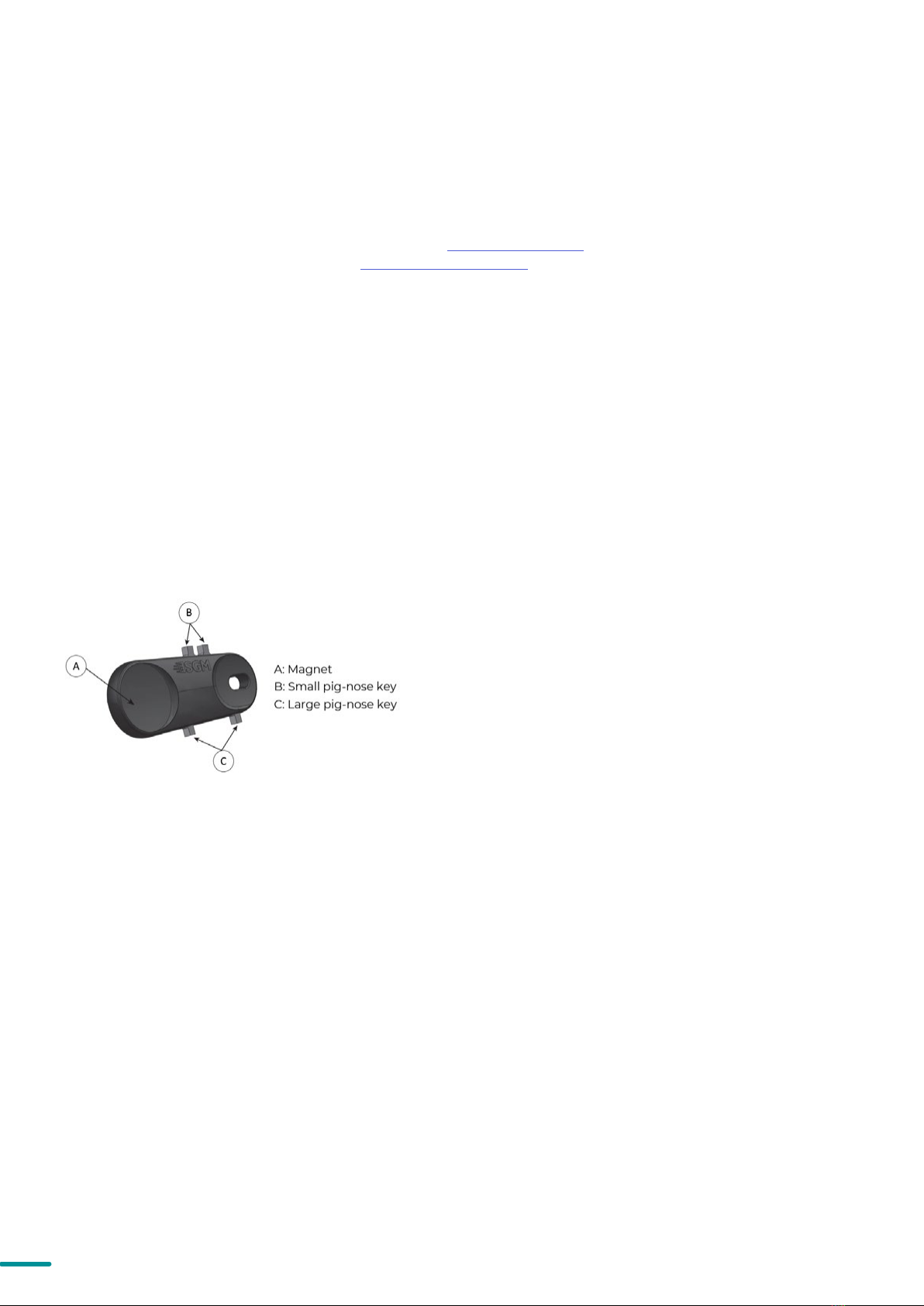
STEP 1: Using a SGM magnetic spanner tool, place the magnet
close to the LED indicator, and wait for 3 seconds. The LED
indicator will blink orange for 1-2 seconds, beforeswitching to
static green again. The fixture can now be paired to a new
transmitter.
STEP 2: Select “connect” or “link” on a wireless DMX transmit-
ter. The transmitter and the internal SGM receivershould now
be linked together.
Repeat the process to link the fixture to another transmitter.
To disconnect the G-7 BeaSt POI from the currently paired wireless transmitter, simply hold the magnet for 3
seconds over the LED indicator. The LED indicator blinks orange for 1-2 seconds, switching later to green again. The
fixture is now logged off.
Fig 13: POI Spanner
WIRELESS DATA CONNECTION
STEP 1: Launch SGM RDM Addressing Tool. Click Full Discovery and look for the green light to illuminate on the
fixture. If the green light does not appear, cycle power or refer to troubleshooting.
The Green light will not light up as a consequence of doing a discovery!
STEP 2: Select the standard settings tab and enter a DMX address and a personality/mode of operation. These
modes must match the control mode in the controller which will control the fixture. Look for the LED indicator to
blink to confirm setting change.
The Green light will not blink as a consequence of changing mode!
DMX modes for POI and Std versions are identical. Refer to CONFIGURING THE DEVICE later in this manual for
specifics for more information on fixture functions. Visit www.sgmlight.com to see all DMX charts available under
STEP 3: If necessary for the application, click advanced settings to set the fan mode, dimming curve, calibration or
to reset to factory defaults.
STEP 4: Disconnect POI Uploader cable.
Repeat as required for multiple fixtures.
Refer to "Factory default" on page 30 for defaults.
PLEASE NOTE! REMOTE DEVICE MANAGEMENT RDM REQUIRES A CORRECTLY INSTALLED AND TERMINATED
DMX CABLE.
When setting addresses through RDM and using USB dongles, it may be necessary to disable “USB selective
suspend” to ensure a proper voltage to the DMX link. If any lag or trouble occurs when addressing, decrease the
cable length range to <12 m. and only address one fixture at a time.
LED INDICATOR
The LED indicator is located on the fixture’s yoke arm and shows the current status of the fixture.
The LED indicator can have different colors and three possible stages: static, flashing, or off.
• Solid Orange: Fixture is starting up.
• Blinking Orange - Green: Fixture is resetting its
functions.
• Blinking Green: Reset has completed, no errors
and no wireless or wired DMX connection.
• Solid Green: Wireless and / or wired DMX con-
nected.
• Blinking Green - Orange - Red: Fixture is resetting
and error(s) has occurred during reset.
• Blinking Green - Red: Reset has completed but
error(s) occurred during reset.
• Solid Red (3 seconds): Hall sensor is activated.
When activated for longer than 3 seconds,
wireless DMX connection is logged off.
• Off: fixture is off or LED indicator is set to au-
to-dimming (set via RDM).

19 Product Version 1.0 | Revision E | Released 2023-01-11
Figure 15: G-7 Spot base with dimensions
Figure 14: G-7 Spot base with Omega brackets
MOUNTING
All SGM POI fixtures have M10 size attachment
points to mount the supplied brackets or
directly to a structure. The M-10 screws are
included in the package in the same amount
as the number of M-10 nuts in the base.
The G-7 Spot POI base has six M-10 nuts that
can be used for installation and rigging. The
SGM Omega bracket (not included) or a
customized bracket is needed to install the
fixture. Consider the dimensions below of the
G-7 Spot POI base for customized mounting
bracket purposes.
over 1000
up to 2000
over 400
up to 1000
over 120
up to 400
over 30
up to 120
over 6
up to 30
over 3
up to 6
Nominal size
Tolerances according to
ISO 2768-1: M
Permissable
deviations
0,1
0,5
up to 3
0,1
0,2
0,3
0,5
0,8
1,2
33,5mm
1,32in
71,5mm
2,81in
3,5mm
0,14in
108,5mm
4,27in
323mm
12,72in
106mm
4,17in
75mm
2,95in
106mm
4,17in
249mm
9,80in
71,5mm
2,81in
255,9mm
10,08in
255,9mm
10,08in
A
15mm
0,59in
37mm
1,46in
8x
18mm
0,71in
8x
14mm
0,55in
DETAIL A
SCALE 2 : 3
REVISIONS
REV.
DESCRIPTION
ECO
DATE
CHANGED BY
G-7 Base asm
42000422-F
WEIGHT: 17945.24
N/A
Material <not specified>
SHEET 1 OF 1
SCALE:1:3
DWG NO.
TITLE:
MATERIAL:
DATE
NAME
DEBUR AND
BREAK SHARP EDGES
FINISH:
Created By
All Dimensions are
in mm
DO NOT SCALE
DRAWING
A3
Last saved By
bar
25. august 2022 10:18:07
21. februar 2018 11:00:27
MLA
PAPER SIZE:

20 Product Version 1.0 | Revision E | Released 2023-01-11
OMEGA BRACKETS
The SGM POI Omega bracket suited for M-10 holes can be ordered as an accessory. Contact your local SGM dealer
for further information on correct POI-rated mounting.
Figure 16: Omega bracket
Figure 17: Omega bracket attachment
Table of contents
Other SGM Floodlight manuals


