BEGA Gantenbrink-Leuchten KG · Postfach 31 60 · 58689 Menden · info@bega.com · www.bega.com
4/4
Leuchtmittel
Modul-Anschlussleistung 21,6W
Leuchten-Anschlussleistung 24W
Bemessungstemperatur ta=25 °C
Umgebungstemperatur ta max =45 °C
84 984 K3
Modul-Bezeichnung LED-1145/930
Farbtemperatur 3000K
Farbwiedergabeindex CRI >90
Modul-Lichtstrom 2770lm
Leuchten-Lichtstrom 333lm
Leuchten-Lichtausbeute 13,9 lm / W
84 984 K4
Modul-Bezeichnung LED-1145/940
Farbtemperatur 4000K
Farbwiedergabeindex CRI >90
Modul-Lichtstrom 2910lm
Leuchten-Lichtstrom 350lm
Leuchten-Lichtausbeute 14,6 lm / W
Lamp
Module connected wattage 21.6W
Luminaire connected wattage 24W
Rated temperature ta=25 °C
Ambient temperature ta max =45 °C
84 984 K3
Module designation LED-1145/930
Colour temperature 3000K
Colour rendering index CRI >90
Module luminous ux 2770lm
Luminaire luminous ux 333lm
Luminaire luminous efciency 13,9 lm / W
84 984 K4
Module designation LED-1145/940
Colour temperature 4000K
Colour rendering index CRI >90
Module luminous ux 2910lm
Luminaire luminous ux 350lm
Luminaire luminous efciency 14,6 lm / W
Lampe
Puissance raccordée du module 21,6W
Puissance raccordée du luminaire 24W
Température de référence ta=25 °C
Température d’ambiance ta max =45 °C
84 984 K3
Désignation du module LED-1145/930
Température de couleur 3000K
Indice de rendu des couleurs CRI >90
Flux lumineux du module 2770lm
Flux lumineux du luminaire 333lm
Rendement lum. d’un luminaire 13,9 lm / W
84 984 K4
Désignation du module LED-1145/940
Température de couleur 4000K
Indice de rendu des couleurs CRI >90
Flux lumineux du module 2910lm
Flux lumineux du luminaire 350lm
Rendement lum. d’un luminaire 14,6 lm / W
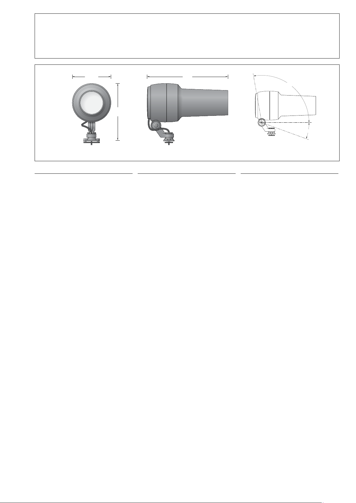
Lichttechnik
Ausstrahlwinkel 14°-30° Lighting technology
Beam angle 14°-30° Technique d’éclairage
Angles de rayonnement 14°-30°
Reinigung · Pege
Leuchte regelmäßig mit lösungsmittelfreien
Reinigungsmitteln von Schmutz und
Ablagerungen säubern.
Dafür keinen Hochdruckreiniger verwenden.
Cleaning · Maintenance
Clean luminaire regularly with solvent-free
cleansers from dirt and deposits.
Do not use high pressure cleaners.
Nettoyage · Entretien
Nettoyer régulièrement le luminaire et le
débarrasser des dépôts et des souillures.
Ne pas utiliser de nettoyeur haute pression.
Austausch des LED-Moduls
Die Bezeichnung des LED-Moduls ist auf einem
Etikett in der Leuchte vermerkt.
BEGA Ersatzmodule entsprechen in Lichtfarbe
und Lichtleistung den ursprünglich verbauten
Modulen.
Der Austausch kann mit handelsüblichem
Werkzeug durch qualizierte Personen erfolgen.
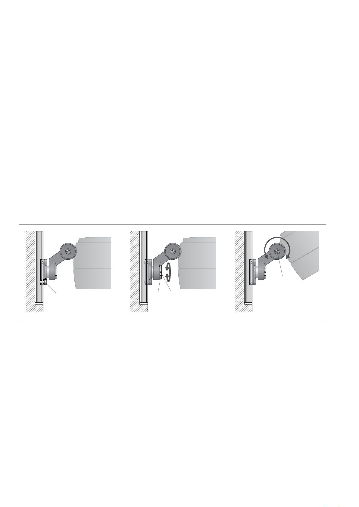
Anlage spannungsfrei schalten.
Verriegelungsstift (Innensechskant SW2,5) auf
der Rückseite im Scheinwerfergehäuse lösen.
Objektivabdeckung linksherum drehen und
abheben.
Die 4Befestigungsschrauben der
Objektiveinheit (TorxantriebT20) lösen und die
komplette Objektiveinheit abnehmen.
LED-Modul austauschen.
Bitte beachten Sie die Montageanleitung des
LED-Moduls.
Objektiveinheit aufsetzen und befestigen.
Scheinwerfer einschalten, Gobo Motivgröße
und -schärfe überprüfen und ggf. nachjustieren.
Objektivabdeckung so auf das
Scheinwerfergehäuse aufsetzen, dass
die Kerben im Scheinwerfergehäuse und
Objektivabdeckung übereinander liegen.
Objektivabdeckung rechtsherum bis zum
Anschlag aufdrehen.
Verriegelungsstift einschrauben.
Replacing the LED module
The designation of the LED module is noted on
a label in the luminaire.
The light colour and light output of BEGA
replacement modules correspond to those of
the modules originally tted.
The module can be replaced by qualied
persons using standard tools.
Disconnect the system.
Loosen the locking pin (hexagon socket wrench
SW 2.5) on the back of the oodlight housing.
Turn the lens cover clockwise and lift it off.
Undo the 4 mounting screws of the lens unit
(Torx drive T20) and remove the complete lens
unit.
Replace LED module.
Please follow the installation instructions for the
LED module.
Replace and secure the lens unit.
Switch on the oodlight, check the Gobo motif
size and focus, and adjust as needed.
Position the lens cover on the oodlight
housing so that the notches in the oodlight
housing and the lens cover are congruent.
Srew on the lens cover clockwise until the stop.
Screw in the locking pin.
Remplacement du module LED
La désignation du module LED est inscrite sur
une étiquette collée dans le luminaire.
Les modules de rechange BEGA
correspondent aux modules d’origine en
termes de couleur de lumière et de ux
lumineux. Le module LED peut être remplacé
par une personne qualiée à l’aide d’outils
disponibles dans le commerce.
Travailler hors tension.
Desserrer la goupille de verrouillage (six pans
creux SW2,5) au dos du boîtier du projecteur.
Tourner le cache de l’objectif vers la gauche et
le soulever.
Dévisser les 4vis de xation de l’unité de
l’objectif (couple de serrage Torx T20) et retirer
l’unité complète.
Remplacer le module LED.
Respecter la notice de montage du module
LED.
Positionner l’unité de l’objectif et la xer.
Allumer le projecteur, vérier la taille et la
résolution du motif Gobo et au besoin,
procéder aux ajustements.
Placer le cache de l’objectif sur le boîtier du
projecteur de manière à ce que les encoches
du boîtier du projecteur et du cache de
l’objectif se superposent.
Fixer le cache de l’objectif en tournant vers la
droite jusqu’à la butée.
Visser la goupille de verrouillage.
Ergänzungsteile
Für diese Leuchte empfehlen wir folgende
BEGA Lichtmaste:
Prolmaste aus Aluminium, lackiert
84 700 quadratisch H 4000 mm
84 701 quadratisch H 6000 mm
84 702 rund H 4000 mm
84 703 rund H 6000 mm
Prolmaste mit Leimholz nach DINEN14 080
84 696 quadratisch H 4000 mm
84 697 quadratisch H 6000 mm
84 698 rund H 4000 mm
84 703 rund H 6000 mm
Accessories
For this luminaire we recommend the following
BEGA luminaire poles:
Prole poles made of lacquered aluminium
84 700 square H 4000mm
84 701 square H 6000mm
84 702 round H 4000mm
84 703 round H 6000mm
Prole poles with glued laminated wood in
accordance with DINEN14 080
84 696 square H 4000mm
84 697 square H 6000mm
84 698 round H 4000mm
84 703 round H 6000mm
Accessoires
Pour ce luminaire nous recommandons les
mâts BEGA suivants :
Mâts prolés en aluminium laqué
84 700 carré H 4000mm
84 701 carré H 6000mm
84 702 rond H 4000mm
84 703 rond H 6000mm
Mâts prolés avec bois lamellé-collé selon
DINEN14 080
84 696 carré H 4000mm
84 697 carré H 6000mm
84 698 rond H 4000mm
84 703 rond H 6000mm
Zu den Ergänzungsteilen gibt es eine
gesonderte Gebrauchsanweisung. For the accessories a separate instructions
for use can be provided upon request. Une che d’utilisation pour ces accessoires est
disponible.
Ersatzteile
Blende ø 20 mm 16 006501
Blende ø 30 mm 16 006502
Objektivabdeckung grat 25 000 165
Objektivabdeckung silber 25 000 166
LED-Netzteil DEV-0412/600
LED-Modul 3000 K LED-1145/930
LED-Modul 4000 K LED-1145/940
Dichtung Gehäuse 83 000 521
Dichtung Objektivabdeckung 83 001 952
Spares
Shield ø 20 mm 16 006501
Shield ø 30 mm 16 006502
Lens cover graphite 25 000 165
Lens cover silver 25 000 166
LED power supply unit DEV-0412/600
LED module 3000 K LED-1145/930
LED module 4000 K LED-1145/940
Gasket housing 83 000 521
Gasket Lens cover 83 001 952
Pièces de rechange
Visière ø 20 mm 16 006 501
Visière ø 30 mm 16 006 502
Cache de l’objectif graphite 25 000 165
Cache de l’objectif argent 25 000 166
Bloc d’alimentation LED DEV-0412/600
Module LED 3000 K LED-1145/930
Module LED 4000 K LED-1145/940
Joint du boîtier 83 000 521
Joint Cache de l’objectif 83001 952