SGS GPA520 User manual

FOR YOUR SAFETY
PLEASE READ THESE INSTRUCTIONS CAREFULLY
AND RETAIN THEM FOR FUTURE USE.
OWNER’S MANUAL
GPA520
PETROL AUGER
NoNo

PAGE 3
PAGE 2
SPECIFICATION
MODEL No GPA520
ENGINE SIZE 52 cc
MAX POWER 1.8 kW
MAX SPEED 7500 RPM
FUEAL TANK CAPACITY 800 ml
NOISE LEVEL 116 dB
WEIGHT 19.20 kg
WARNING
Read and understand the instruction manual before
using the blower. Restrict unit to users who understand
and will follow all warnings and safety rules in this
manual.
Approved protective goggles or visor, ear protection,
gloves, and face mask in dusty environments must be
worn.
WARNING: Danger of inhaling carbon monoxide - To
avoid poisoning operate this machine only in well
ventilated areas. Never start or run the engine in-
side a sealed room or building.
GENERAL SAFETY PRECAUTIONS
WARNING: Fire hazard - keep fuel away from all
sources of ignition.
You MUST STOP using the machine if:
• The engine speed changes with no control.
• In case of misfire
• In case of high vibration.
• When flames or smoke appear.
• In rain or stormy weather.
DO NOT attempt to lift or move the machine while the
engine is running. DO NOT put hands or feet near rotat-
ing parts.
DO NOT touch or allow clothing and other flammable
materials to come into contact with the engine or
muffler. These parts get extremely hot from operation.
If the machine should start to make an unusual noise or
vibration, immediately shut off the engine, disconnect
the spark plug HT lead, and check for the cause.
WWW.SGS-ENGINEERING.COM

PAGE 5
PAGE 4
1. Take the Allen key and box spanner (small end) and undo the bolt that
passes through the end of the auger bit.
2. Once the bolt is removed you can slot the auger over the end of the
power unit drive shaft.
3. Align the hole in the shaft with the holes in the auger bit.
4. Pass the bolt through the auger and shaft then fit the nut and fully
tighten.
AUGER BIT ASSEMBLY
FUELING
1. Fill the mixing bottle with fresh unleaded petrol to the fuel level line. You
MUST only use fresh unleaded fuel and 2 stroke engine oil mixture.
2. For the first time ONLY a mixing ratio of 25:1 should be used to
lubricate all engine parts to an optimum level. Thereafter the mix is 40:1.
3. Unscrew the fuel tank cap and carefully add the fuel/2 stroke mixture as
in section 2. DO NOT overfill and allow a 25mm gap at the top of the tank.
Once full replace and correctly tighten the fuel cap. DO NOT use straight
unleaded petrol. From empty the fuel tank holds 800ml.
WWW.SGS-ENGINEERING.COM

PAGE 7
PAGE 6
MAINTENANCE
1. Position the machine in such a way that it cannot move during use,
maintenance, cleaning, adjustment, assembly of accessories or spare parts,
as well as under storage.
2. DO NOT change the engine governor settings or over-speed the engine.
The governor controls the maximum safe operating speed of the engine.
3. Use only attachments and accessories approved by the manufacturer.
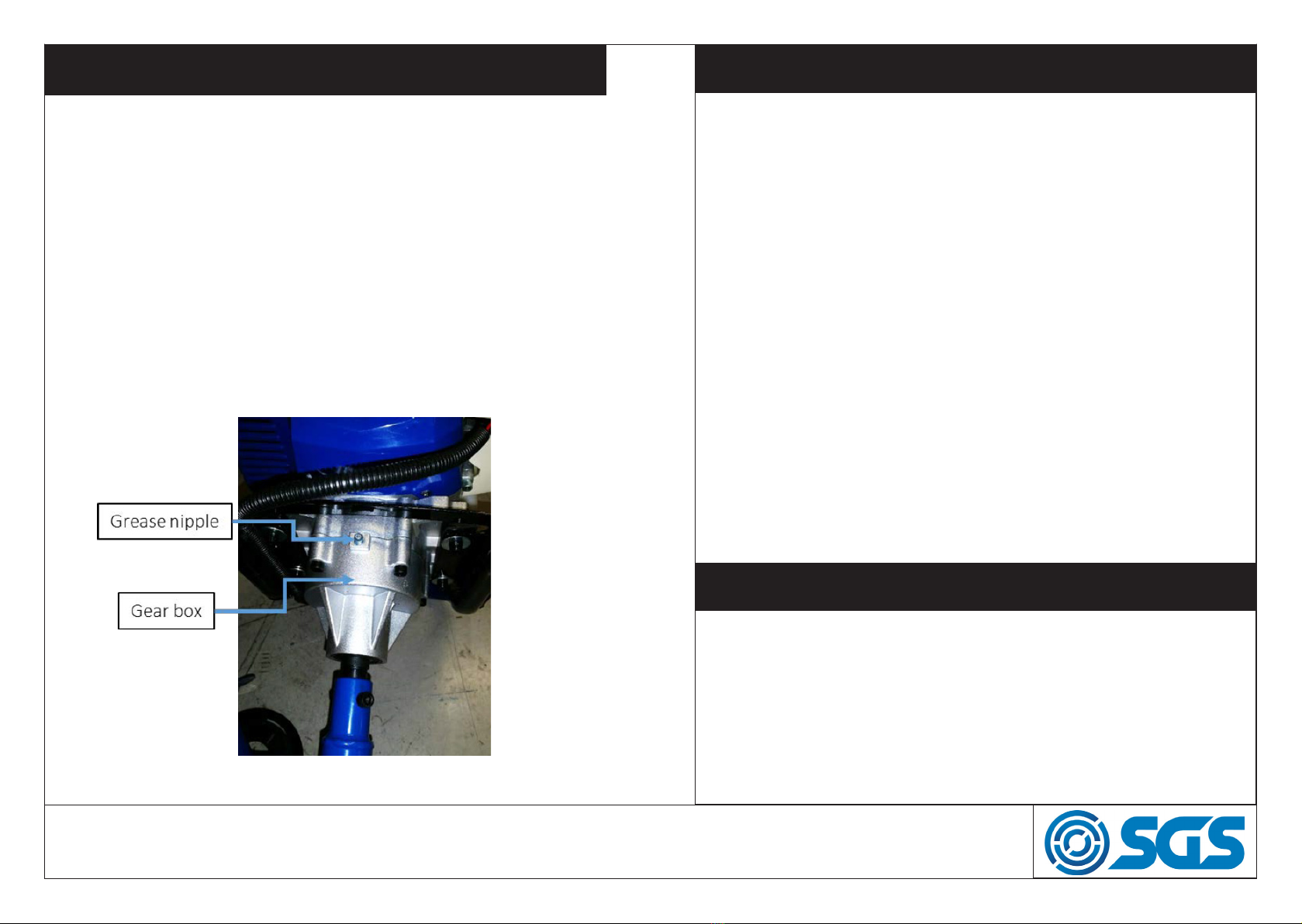
4. Maintain the machine and check for misalignment or binding of moving
parts, broken parts and any other condition that may affect the machine’s
operation. If damaged, have the machine repaired before reuse.
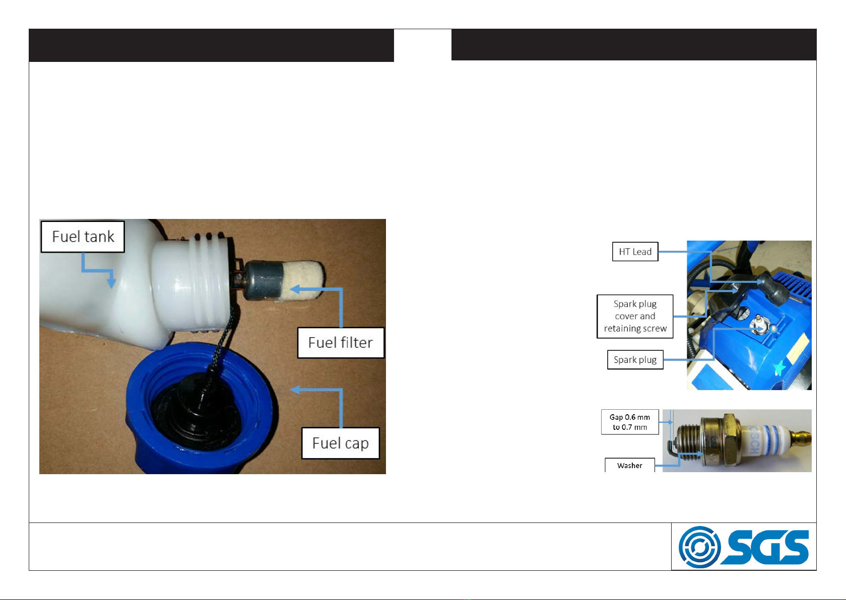
5. Keep the engine, exhaust and muffler free of grass, leaves, excessive
grease or carbon build up to reduce the chance of a fire hazard.
6. Keep handles dry, clean and free from debris. Clean the machine after
each use.
7. Thoroughly inspect the area to be worked, keep the working area clean
and free of debris to prevent tripping. Operate on a flat level ground.
8. Keep all bystanders, children, and pets at least 23m (75 feet) away.
9. Before starting the auger, make sure that the area to be drilled is free of
all underground obstacles such as power cables, water and drainage pipes.
10. NEVER allow an accumulation of earth or drilled material to build up
on the earth auger drill bit, this will prevent proper discharge from the hole
and will make the auger heavy to handle.
11. NEVER attempt to unclog either the auger drill bit while the engine is
running. Immediately shut off the engine. Allow the auger drill bit to come
to a complete stop. Remove the clogged material. Inspect for damage and
check for any loose parts for repair or replacement.
1. Before starting make sure machine is clear of materials and all
non-essential persons.
2. Put the power switch to ON position. Move the choke lever to START
position.
3. Press the primer bulb 7/8 times. Holding the machine firmly pull the
recoil starter handle until machine starts.
4. When machine starts adjust the choke lever to the RUN position until
machine runs smoothly. Allow the engine to warm up for a few minutes.
5. Put the switch to ON position. Make sure the choke lever is in the RUN
position. Holding the machine firmly pull the recoil starter handle until
machine starts. Allow the engine to warm up for a few minutes.
6. Before stopping the machine allow the engine to cool down for a few
minutes, by allowing it to run without throttle. You MUST allow the auger
drill bit to come to a full stop before carrying out any maintenance on the
machine. Allow the machine to cool down with no throttle applied. Turn the
power switch OFF. If not already in RUN position move the choke to the
RUN position.
STARTING & STOPING PROCEDURE
WWW.SGS-ENGINEERING.COM

PAGE 9
PAGE 8
AIR FILTER
Never let the engine run without the air filter being fitted. A dirty air filter
element affects the engine performance, increases fuel consumption and
makes it difficult to start.
You MUST make sure that the housing is free of dust and debris.
DO NOT allow any dust or debris to enter the carburetor.
1. Push clip (1) down and pull filter cover (2) away from machine, take care
to release lower clips (3).
2. Remove the filter (4) by pressing clip (5) and lifting filter clear.
3. Wash with soap and water. Never use petrol or benzene!
4. Allow the filter to air dry. To replace the filter reverse the above process.
1. Before starting - inspect machine and work area for any danger.
2. Start slowly with half throttle and keep a firm grip on both handles of the
auger at all times. Keep a wide stance.
3. After engine warms up Accelerate
the engine, to accelerate the engine to
working speed squeeze the throttle lever
toward the main handle.
4. DO NOT force the auger drill bit into
the ground. If the machine jams you
MUST release the throttle and move the
auger drill bit before re-commencing
work.
5. To remove blockages DO NOT under
any circumstances use your hands.
STOP and disable the machine and clear
the auger drill bit of materials which have
become stuck to auger bit.
7. Check and maintain fuel level regu-
larly, and maintain the fuel/oil mix to the
correct ratio. Frequently check the auger and make sure that all deposits
are removed from the auger drill bit.
8. At regular intervals, check the tightness of all nuts, bolts and screws.
If the auger drill bit hits an obstacle check for damage. If the machine vi-
brates badly stop the machine and take it to a service dealer.
9. NEVER use a “pressure washer” to clean your auger. Water can pen-
etrate the power unit and cause damage the engine. The use of pressure
washers will result in shortened life and reduce serviceability. Shut down
the engine, wait for all moving parts to come to a complete stop, remove
HT lead, and then wait for 5 minutes before performing maintenance on
the tool.
OPERATION
WWW.SGS-ENGINEERING.COM

PAGE 11
PAGE 10
SPARK PLUG
1. The spark plug MUST be fully tightened otherwise the engine will
overheat causing damage. Always complete the following steps after the
engine has been turned off and allowed to cool down.
2. To make sure the engine runs correctly a spark plug gap of 0.6 - 0.7 mm
must be maintained and the spark plug must be free of carbon deposits.
3. To remove the spark pull off the HT lead and then undo the spark plug
using the supplied box spanner/T bar in an anti-clockwise direction.
4. Once the plug has been removed check it for visual damage, electrode
wear and carbon deposits. Replace a damaged or badly worn spark plug.
Clean off any carbon deposits by using a soft brass brush.
5. Check the gap with a
feeler gauge and adjust
electrode at the correct
gap of 0.6 - 0.7 mm.
6. Check the spark plug
washer for damage and
replace if required.
7. Refit the spark plug by
hand to make sure it does
not cross thread, tighten
the spark plug to a torque
of 12/15Nm.
FUEL FILTER
1. A clogged fuel filter can cause lack of power and poor pickup. Check
the fuel filter every 15 use hours.
2. Remove the fuel cap and empty the remaining fuel into an approved
container.
3. With a small wire hook pull out the fuel line and filter out of the tank.
4. Disconnect the filter spray with a carburetor cleaning solvent then clean
by blowing air from inside filter to outside. Reverse to process to re-instate
the filter. Replace filter as required.
WWW.SGS-ENGINEERING.COM

PAGE 13
PAGE 12
STORAGE
1. Clean the outside of the machine, drive axle, shield and nylon cutting
head.
2. Remove all fuel from the fuel tank.
3. After all the fuel is drained, start the engine.
4. Allow the engine to run in idle until engine stops alone. This allows the
fuel to be removed from the carburetor.
5. Allow engine to cool down (about 5 minutes).
6. Use a spark plug wrench, remove the spark plug.
7. Pour 1 teaspoon of clean 2-cycle oil into the combustion chamber. Slow-
ly pull the starter rope several times to coat internal components. Replace
the spark plug.
8. Store the machine in a cool, dry place away from any source of ignition
such as an oil burner, water heater etc.
9. When transporting the machine make sure that no fuel is allowed to leak
out.
Engine Type: Single cylinder, 2 stroke, air-cooled engine, 1E43F-B
Start Method: Recoil
Clutch type: Centrifugal
Fuel: 40:1 ratio Semi-Synthetic 2 stroke oil/Unleaded petrol
Grease: High temperature gearbox grease - 20 grams
Drill sizes diameter/length:
100 x 800 mm
150 x 800 mm
200 x 800 mm
GEAR BOX
1. Use a high temperature gearbox grease.
2. Check the gear box grease every 30 hours of use and fill as required.
Thereafter check and top-up after every 25 hours. N.B. 20 grams is
sufficient for a full top-up.
3. To fill with or top-up with grease apply grease with a grease gun to the
grease nipple.
4. Recommended change interval. 1st check after 30 hours of use.
Thereafter every 25 hours of use.
5. If you do not follow these steps, deposit may arise in the carburetor.
This will cause starting difficulties and may cause permanent damage.
TECHNICAL SPECIFICATION
WWW.SGS-ENGINEERING.COM

PAGE 15
PAGE 14
PARTS LIST
PARTS DIAGRAM
No Part name Code Qty No Part name Code Qty
1 M5x20 bolt 903960 6 37 ø10x30x7 oil seal 903996 1
2 Side cover 903961 1 38 ø5x10 straight pin 903997 4
3 Bolt 903962 2 39 Bracket of oil lter 903998 1
4 Washer 903963 2 40 M5x55 bolt 903999 2
5 Clutch 903964 1 41 Air lter 904000 1
6 Washer 903965 2 42 Cover of air lter 904001 1
7 M8 Nut 901995 1 43 Plate 904002 1
8 Flywheel 903967 1 44 Le crankcase 904003 1
9 M5x20 screw 903761 10 45 Bearing 6202 904004 2
10 Ingion Coil assembly 903969 1 46 Woodru key 904005 1
11 Cylinder 903970 1 47 Cranksha 904006 1
12 M5x20 bolt 903960 4 48 Gasket of cranksha 904007 1
13 Spark plug 903972 1 49 Right crankcase 904008 1
14 M4x10 bolt 903542 3 50 ø12xø22x7 oil seal 904009 1
15 Cylinder cover 903974 1 51 Drive plate 904010 1
16 Top cover 903975 1 52 M8 nut 901995 1
17 M5x14 bolt 901514 1 53 Starter assembly 904012
18 Plate 903977 1 54 ST bolt 904013 1
19 Guide cover 903978 1 55 Ratchet wheel 904014 1
20 ST4x10 bolt 903979 3 56 Torisonal spring 904015 1
21 M6x55 screw 903980 2 57 Rope sheave 904016 1
22 Insulaon mat for muer 903981 1 58 Coil spring 904017 1
23 M5x10 screw 901696 1 59 Nut 904018 2
24 Muer 903983 1 60 Cover of starter 904019 1
25 Insulaon mat for muer 903984 1 61 Start rope 904020 1
26 Gasket of cylinder 903985 1 62 Start knob 904021 1
27 Piston ring 903986 2 63 Knot 904022 1
28 Piston 903987 1 64 Fuel tank assembly 904023
29 Piston pin 903988 1 65 Fuel tank cap 904024 1
30 Clamp spring 903989 2 66 Oil out via 904025 1
31 Bearing 903990 1 67 Clamp spring 904026 2
32 Gasket 903991 1 68 Fuel pipe 904027 3
33 Intel air pipe 903992 1 69 Fix of oil pipe 904028 1
34 Gasket of carburetor 903993 1 70 Fuel lter 904029 1
35 Carburetor 903994 1 71 Fuel tank 904030 1
36 M5x35 bolt 903995 4 72 Bracket of tank 904031 1
WWW.SGS-ENGINEERING.COM

PAGE 17
PAGE 16
PARTS DIAGRAM
PARTS LIST
No Part name Code Qty
1 Gasoline engine 903933 1
2 Gearcase fixed plate 903934 1
3 Anti-vibration rubber cushion 903935 2
4 Handle 903936 1
5 Flat pad ø6.4xø22x1.5 903937 4
6 Bolt and spring pad Mx35 903938 4
7 Clutch cover 903939 1
8 Bearing ø19xø41x7 903940 2
9 Gearcase cover 903941 1
10 Gearcase cover 903942 1
11 Bearing ø16xø35x11 903943 11
12 Snap ring ø19 903944 1
13 Gear 44T 903945 1
14 Gear 10T 903946 1
15 Straight pin ø5x10 903947 2
16 Gearcase 903948 1
17 Bolt M6x30 903949 2
18 Output shaft 903950 1
19 Oil seal ø19xø37x7 903951 1
20 Bolt M6x50 903952 4
21 Bolt M6x8 903953 1
22 Gear 48T 903954 1
23 Gear 7T 903955 1
24 Throttle level 903956 1
25 Bolt M8x50 903957 1
26 Nut M8x6.5 901995 1
27 Driller 903959 1
WWW.SGS-ENGINEERING.COM

EC Declaration of Conformity
This is an important document and should be retained
MANUFACTURER’S NAME:
TYPE OF EQUIPMENT:
PART NUMBER:
I, the undersigned, hereby declare that the equipment specied above
conforms to the above European Communities Directive(s) and
Standard(s).
PLACE:
DATE: (Signature)
Robert Wyatt
Company Secretary
Derby, UK
24th NOV 2018
SGS Engineering (UK) Ltd
West Side Park
Raynesway
Derby, DE21 7AZ
PETROL AUGER
GPA520
2006/42/EC Machinery Directive (MD)
2004/108/EC Electromagnetic Compatibility Directive (EMC)
97/68/EC amended by 2010/26/EC Directive of Emission
2000/14 EC & 2005 /88 EC Directive of EU Noise
APPLICATION OF EC COUNCIL DIRECTIVES / STANDARD:
Table of contents
Other SGS Tools manuals