ShadeLab Kumo User manual

Assembly manual


INDEX
1 - INTRODUCTION ..............................................................page 4
1.1 - Symbols used in the manual ....................................................... page 4
1.2 - Personnel requirements .............................................................. page 4
1.3 - Equipment necessary .................................................................page 5
1.4 - Before starting assembly ............................................................page 5
2 - SAFETY .......................................................................page 6
2.1 - General safety information.......................................................... page 6
2.2 - Working environment ................................................................. page 6
3 - ASSEMBLY TECHNICAL TABLES ..........................................page 7
3.1 - Table of minimum dimensions ....................................................page 7
3.2 - Motor power table ...................................................................... page 7
3.3 - Table of cutting dimensions ........................................................ page 8
4 - KUMO COMPONENTS AND DIAGRAMS ..................................page 9
4.1 - Tilting diagrams .......................................................................... page 9
4.2 - Awning components ................................................................... page 10
4.3 - Material necessary for assembly ................................................ page
11
5 - AWNING ASSEMBLY ........................................................page 12
6 - REGULATING THE AWNING ................................................page 18
6.1 - Troubleshooting .......................................................................... page 19
7 - REMOVING AND PACKING THE AWNING ................................page 21
7.1 - Removing .................................................................................... page 21
7.2 - Packing ....................................................................................... page 21

4 | | ASSEMBLY
1 - INTRODUCTION
This “assembly manual” for KUMO awnings has been produced by SHADELAB to
supply the indications necessary for the operations of assembling the components
that make up the product.
Assembly must be carried out by personnel with suitable technical and professional
qualifications, in accordance with the respective national laws or regulations (see Par.
1.2 “Personnel requirements”).
It is forbidden to eliminate, rewrite or alter the pages in the manual and their content.
This manual must be kept intact in all its parts, in an easily accessible place.
SHADELAB reserves the right to update the production and the respective manuals,
without being obliged to update the previous production and manuals.
SHADELAB reserves all rights to this manual: no total or partial reproduction is al-
lowed without authorisation in writing.
1.1 - Symbols used in the manual
Shown below are the WARNING symbols used in this manual:
IMPORTANT
Indications and advice to be observed to ensure a correct use of the awning. Failure to
follow these indications may endanger the integrity and/or resistance of the product.
ATTENTION
DANGER FOR THE OPERATOR! Instructions and indications to be assessed and fol-
lowed with care. Failure to follow these indications may endanger personal safety.
1.2 - Personnel requirements
The personnel appointed to perform this operation must possess a technical knowl-
edge of the product, acquired by assembling similar products for at least one year or
after having followed a suitable technical training course.

| ASSEMBLY | 5
1.3 - Equipment necessary
To ensure the correct assembly of the mechanical part, of the textile part, and conse-
quently the optimum operation of the finished product, it is necessary to be in pos-
session of the following equipment:
»fabric rolling frame;
»awning assembly frame with arms and vertically movable positioning bar;
»electric and pneumatic screwdriver;
»complete set of tools.
1.4 - Before starting assembly
IMPORTANT
Some components must be cut to suit the dimensions of the awning that is to be ob-
tained (see Par. 3.3 “Table of cutting dimensions”).

6 | | ASSEMBLY
2 - SAFETY
2.1 - General safety information
Follow these safety precautions:
ATTENTION
Wear the garments and personal protection equipment contemplated by the safety
regulations in force for the workplace (protective helmet, gloves, etc.).
ATTENTION
It is forbidden to use the awning to support yourself: risk of serious personal injury and
of damage to the awning itself.
IMPORTANT
Do not lay objects on the awning.
IMPORTANT
This manual is an integral part of the product. Before assembly, carefully read all the
instructions given in this manual.
IMPORTANT
SHADELAB guarantees the EC marking only for products supplied by the company
itself. If any parts have to be replaced with other components not guaranteed by
SHADELAB, the product guarantee will automatically become void and SHADELAB
shall not answer for any malfunctions of the product.
ATTENTION
Some awning components are constantly subject to strong pressure (arms) and, if the
instructions in this manual are not carefully followed, these components may cause
serious harm to persons, animals and things.
ATTENTION
NEVER reuse the arm lock after removing it.
2.2 - Working environment
At the moment of assembly, good natural and/or artificial lighting must be created in
the place where the work is being done.

| ASSEMBLY | 7
3 - ASSEMBLY TECHNICAL TABLES
3.1 - Table of minimum dimensions
Kumo minimum dimensions
Arm projection [cm] Minimum width [cm]
150 190
175 215
200 240
225 265
250 290
275 315
300 340
Tab.1
3.2 - Motor power table
Width [cm]
200 300 400 500
Projections [cm]
150 15/17 N/m
175 25 N/m
200
225
30 N/m
250
275
300
Tab.2
IMPORTANT
For this awning model use motors with an electronic limit switch.

8 | | ASSEMBLY
3.3 - Table of cutting dimensions
Cutting dimensions
Component Type of control Cutting ratio
measurements in [mm]
Cassette
NICE MOTOR L -160
NICE MOTOR WITH EMERGENCY MANOEUVRE L -160
SOMFY MOTOR L -160
SOMFY MOTOR WITH EMERGENCY MANOEUVRE L -160
BECKER MOTOR L -160
BECKER MOTOR WITH EMERGENCY MANOEUVRE L -160
CRANK L -160
Terminal bar
NICE MOTOR L -160
NICE MOTOR WITH EMERGENCY MANOEUVRE L -160
SOMFY MOTOR L -160
SOMFY MOTOR WITH EMERGENCY MANOEUVRE L -160
BECKER MOTOR L -160
BECKER MOTOR WITH EMERGENCY MANOEUVRE L -160
CRANK L -160
Roller
tube
NICE MOTOR L -130
NICE MOTOR WITH EMERGENCY MANOEUVRE L -132
SOMFY MOTOR L -130
SOMFY MOTOR WITH EMERGENCY MANOEUVRE L -130
BECKER MOTOR L -130
BECKER MOTOR WITH EMERGENCY MANOEUVRE L -138
CRANK L -142
Fabric
NICE MOTOR L -170
NICE MOTOR WITH EMERGENCY MANOEUVRE L -170
SOMFY MOTOR L -170
SOMFY MOTOR WITH EMERGENCY MANOEUVRE L -170
BECKER MOTOR L -170
BECKER MOTOR WITH EMERGENCY MANOEUVRE L -170
CRANK L -170
Tab.3

| ASSEMBLY | 9
4 - KUMO COMPONENTS AND DIAGRAMS
4.1 - Tilting diagrams
147
264
230
194
190
231
264
147
PROJECTION
HEIGHT
5°
65°
302
400
375
350
325
300
275
250
225
200
175
150
PROJECTION
HEIGHT
13°
85°
321
400
375
350
325
300
275
250
225
200
175
150
Awning dimensions with arms folded
Wall mounting
Awning dimensions with arms folded
Roof mounting
Arm length and inclination Arm length and inclination
Wall mounting Roof mounting
RECOMMENDED ARM: HOME
RECOMMENDED DIMENSIONS: width 500cm - projection 300cm
5° minimum inclination
13° minimum inclination
65° maximum inclination
85° maximum inclination

10 | | ASSEMBLY
4.2 - Awning components
In the system supplied by SHADELAB the customer will find the following compo-
nents already preassembled:
»2 wall brackets (see ref. 1, fig. 1);
»1 left side support, composed of:
»arm support (see ref. 2, fig. 1);
»lever (see ref. 3, fig. 1);
»1 right side support, composed of:
»arm support (see ref. 4, fig. 1);
»lever (see ref. 5, fig. 1);
»1 cassette, composed of:
»terminal bar (front) (see ref. 6, fig. 1);
»cover (top) (see ref. 7, fig. 1);
»cassette (bottom) (see ref. 8, fig. 1);
»2 arms (see ref. 9, fig. 1);
»2 terminal bar connecting kits (see ref. 10, fig. 1);
»1 conveyor (see ref. 11, fig. 1);
»1 plate with pin (see ref. 12, fig. 1);
»1 brush (see ref. 13, fig. 1);
»1 cap with hole (see ref. 14, fig. 1);
»1 cap with square pin* (see ref. 15, fig. 1);
»1 crank* (see ref. 16, fig. 1).
2
10
10
12
4
5
9
8
11
6
113
7
3fig.1
9
14
115 16
(*) only in the manual version.

| ASSEMBLY | 11
4.3 - Material necessary for assembly
The following spanners must be used to assemble the KUMO awning:
»Allen wrenches (see ref. 1, fig. 2): 3, 4, 5, 6, 10
»Combination spanners (see ref. 2, fig. 2): 10
»Box spanners (see ref. 3, fig. 2): 13
fig.2
1 2 3
12 | | ASSEMBLY
5 - AWNING ASSEMBLY
IMPORTANT
Before starting assembly, the person appointed to do the job must have cut the pieces
to suit the size of the awning that is to be obtained (see tab. 3 par. 3.3).
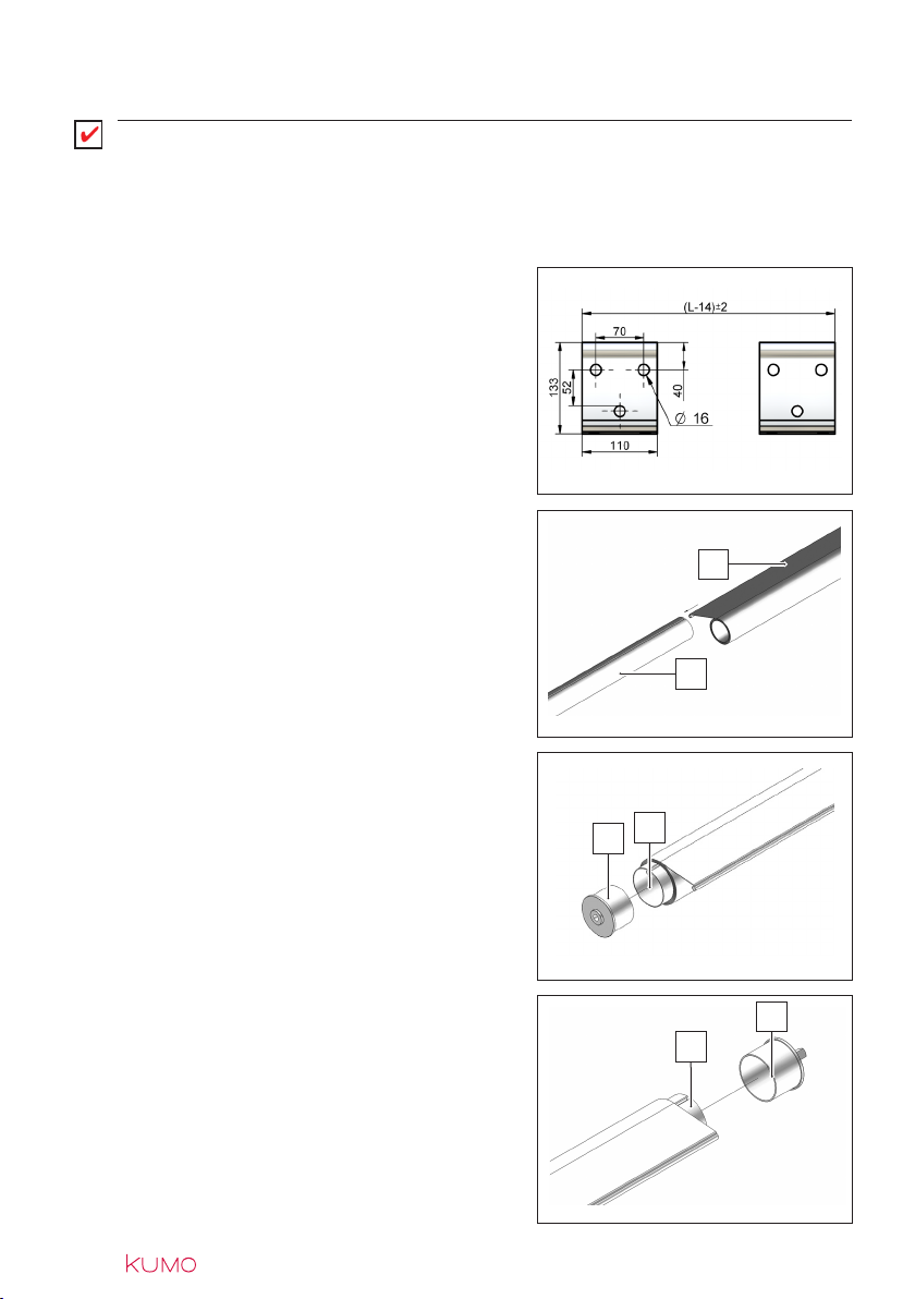
Define the distance of the brackets (see fig.
3) and position them on the awning assembly
frame.
Assemble the fabric (see ref. 1 fig. 4) with
the roller tube (see ref. 2 fig. 4) and roll it up
completely.
Insert the cap with hole (see ref. 3 fig. 5) on
the side opposite the control (see ref. 4 fig.
5).
MANUAL AWNING:
Insert the cap with square pin (see ref. 5 fig.
6) in the roller tube (see ref. 6 fig. 6).
fig.6
fig.4
fig.5
fig.3
1
2
34
5
6
| ASSEMBLY | 13
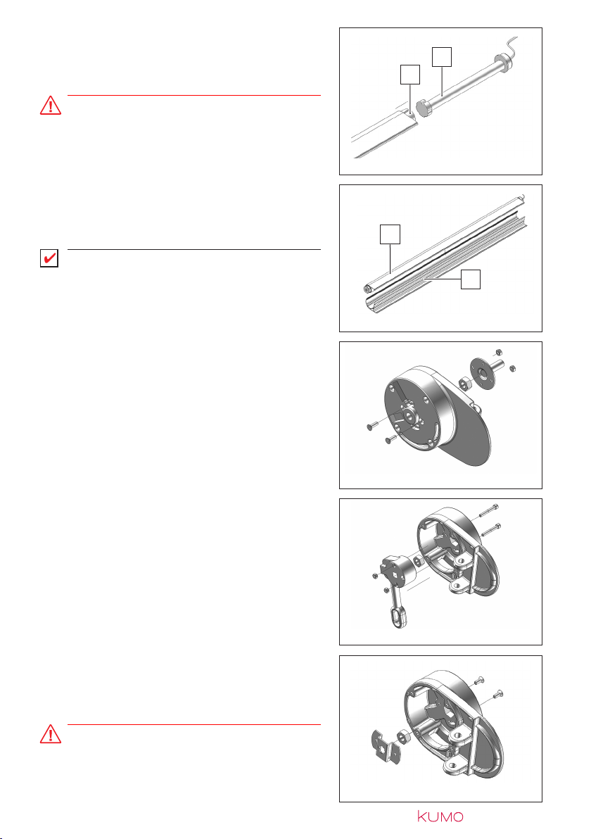
MOTOR-OPERATED AWNING:
Insert the motor (see ref. 7 fig. 7) in the roller
tube (see ref. 8 fig. 7).
ATTENTION
These instructions are of a general nature, so
you must follow the ones given in the motor
manual.
Now insert the roller tube (see ref. 9 fig. 8)
including the fabric, previously rolled up, into
the bottom cassette (see ref. 10 fig. 8).
IMPORTANT
The roller tube must be inserted with the roll-
ing direction facing upwards.
Insert the nut M/14 in the lever seat and as-
semble the plate with pin.
MANUAL AWNING:
Insert the nut M/14 in the lever seat.
Assemble the crank with the screws fitted in
the slots.
MOTOR-OPERATED AWNING:
Insert the nut M/14 in the lever seat.
Assemble the motor plate.
ATTENTION
These instructions are of a general nature, so
you must follow the ones given in the motor
manual.
fig.10
fig.11
fig.8
fig.9
fig.7
8
7
9
10
14 | | ASSEMBLY
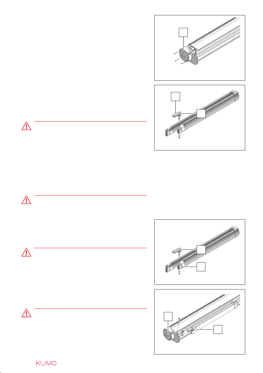
Fix the levers that form the side supports
onto the sides of the bottom cassette (see
ref. 11 fig. 12), ensuring that the correspond-
ing holes are aligned.
Preassemble the plate (see ref. 12 fig. 13) in
the terminal bar connecting kit (see ref. 13
fig. 13), (Allen wrench 5). The screws must
not be fully tightened.
ATTENTION
The arm is provided with a safety band that
blocks the tightening mechanism. Do not
remove this band until the awning has been
completely assembled. Failure to respect the
correct assembly procedure may cause seri-
ous harm to persons, animals and things in
the vicinity.
ATTENTION
NEVER reuse the arm lock after removing it.
Fit the terminal bar connecting kit (see ref. 14
fig. 14) onto the end of the arm (see ref. 15
fig. 14), (box spanner 13).
ATTENTION
Ensure that the two kits are correctly fixed to
the ends of the arms.
Assemble the arms (see ref. 16 fig. 15) on the
respective levers (see ref. 17 fig. 15).
ATTENTION
The arm must be fitted CLOSED. Do not re-
move the safety strap provided; the arm is al-
ways under tension, if it were opened without
control it could cause serious harm to per-
sons, animals and things. fig.15
fig.13
fig.14
fig.12
11
12
13
14
15
16
17

| ASSEMBLY | 15
fig.16
Insert the brush (see ref. 18 fig. 16) in the
cover (see ref. 19 fig. 16).
18
19
Fit the cover (see ref. 20 fig. 17) onto the cas-
sette (see ref. 21 fig. 17), securing it with the
screws.
Set the regulating cylinder at minimum (see
ref. 22 fig. 18). Insert the plate in the slot in
the support (see fig. 18) (Allen wrench 6).
For roof-mounted awnings, the support must
be fitted vertically and the square nut insert-
ed in the slot at the top (see ref. 23 fig. 20).
Fix the supports onto the levers, inserting the
screw in the hole provided (see fig. 19) (Allen
wrench 10).
fig.18
fig.20
fig.19
fig.17
20
21
22
23

16 | | ASSEMBLY
Check that the distance of the terminal bar
connection from the outside of the terminal
bar is 47 mm (see fig. 24); once this has been
checked, the screws can be tightened.
Insert the terminal bar caps (see ref. 28 fig.
25). Check that the terminal bar is centred
with the cassette. Now try to close the awn-
ing.
fig.25
fig.24
28
Assemble the terminal bar inserting the fabric
in the ogive (see ref. 27 fig. 23) in the terminal
bar. Sliding the terminal bar, check that the 2
plates of the terminal bar connections are in
their proper place.
fig.23
27
For sizes larger than 4 m, fix the conveyor to
the centre of the awning (see ref. 26 fig. 22).
26
fig.22
47 mm
fig.21
Install the awning on the brackets fixed to the
frame (see ref. 24 fig. 21). Block the awning
with the screws provided (see ref. 25 fig. 21),
(Allen wrench 5). 24
25

| ASSEMBLY | 17
Check that the awning closes perfectly.
Open the awning and fix the fabric to the ter-
minal bar. Perform two awning opening/clos-
ing cycles.
ATTENTION
Ensure that there are no persons, animals or
things in the vicinity while opening/closing the
awning.
fig.27
fig.26

18 | | ASSEMBLY
6 - REGULATING THE AWNING
Once the awning has been assembled, to check that all the components are correctly
fitted you must:
»Make 2-3 test cycles of opening/closing the awning.
»Regulate any components that prevent the correct and unimpeded opening and closing move-
ment of the awning.
ATTENTION
Ensure that there are no persons, animals or things in the vicinity while opening/clos-
ing the awning.
Regulating the awning:
slacken the side screw (see ref. 29 fig. 28),
(Allen wrench 10). To increase the inclination
slacken the socket-head screw (Allen wrench
6) (see ref. 30 fig. 28). To decrease the incli-
nation tighten the socket-head screw, raising
the terminal bar. After regulation, check that
the terminal bar is perfectly horizontal.
With the awning almost closed, check that
the arms are parallel to the cassette.
If they are not parallel, tighten or slacken the
dowel (see ref. 31 fig. 29) in the lever (Allen
wrench 3), accompanying the arm.
fig.28
fig.29
29
30
31
ATTENTION
After regulation, firmly tighten the side screw.

| ASSEMBLY | 19
6.1 - Troubleshooting
The table below gives some examples of causes/remedies for any difficulties that
might be encountered when testing opening/closing of the awning:
MANUAL AWNING
PROBLEMS CAUSES REMEDIES
Tapered winding of the fabric
Incorrect symmetry of the
arms
Fabric thickness not
uniform
Completely roll up the fabric and
contact the assistance service
Completely roll up the fabric and
contact the assistance service
Tab.4
MOTOR-OPERATED AWNING
Without electronic control unit
PROBLEMS CAUSES REMEDIES
Tapered winding
of the fabric
Incorrect symmetry of the
arms
Fabric thickness not
uniform
Completely roll up the fabric and
contact the assistance service
Completely roll up the fabric and
contact the assistance service
The awning does not roll up
completely
The awning does not open
completely
Incorrect limit switch
adjustment
Motor crown wheel shifts
during movement
Contact the Assistance service
Contact the Assistance service
Motor very
noisy
Wiring error
Faulty motor
Contact the Assistance service
Contact the Assistance service
Motor blocks after 4-5 min-
utes continuous operation
Motor thermal
protection tripped
Let the motor cool for a few minutes
Tab.5

20 | | ASSEMBLY
With electronic control unit
PROBLEMS CAUSES REMEDIES
The awning does not move Faulty fuse
Faulty motor
Wiring error
Contact the Assistance service
Contact the Assistance service
Contact the Assistance service
The awning moves discon-
tinuously
Faulty anemometer Contact the Assistance service
The awning does not roll
up in presence of strong
wind or rain
Wiring error
Faulty anemometer/pluviometer
Contact the Assistance service
Contact the Assistance service
With the radio control the
awning opens or closes
by itself
Wiring error
Fault in the system
Contact the Assistance service
Contact the Assistance service
Tab.6
Table of contents
Other ShadeLab Tent manuals


