ShadeLab KLIP User manual

Installation Manual


INDEX
1 - INTRODUCTION .................................................................................................................................. pag. 2
1.1 - Symbols used in the manual....................................................................................................... pag. 2
1.2 - Personnel qualications ............................................................................................................. pag. 2
1.3 - Necessary equipment ................................................................................................................ pag. 3
1.4 - Before starting installation ......................................................................................................... pag. 3
2 - SAFETY ............................................................................................................................................. pag. 4
2.1 - General safety information ......................................................................................................... pag. 4
2.2 - Working environment................................................................................................................. pag. 5
3 - KLIP COMPONENTS AND DIAGRAMS ................................................................................................ pag. 6
3.1 - Tilting diagrams ......................................................................................................................... pag. 6
4 - KLIP XL COMPONENTS AND DIAGRAMS ........................................................................................... pag. 7
4.1 - Tilting diagrams ......................................................................................................................... pag. 7
5 - INSTALLATION TABLES AND TECHNICAL DRAWINGS ....................................................................... pag. 8
6 - STEIN COMPONENTS AND DIAGRAMS .............................................................................................. pag. 9
6.1 - Tilting diagrams ......................................................................................................................... pag. 9
7 - INSTALLATION TABLES AND TECHNICAL DRAWINGS ....................................................................... pag. 10
8 - KLIP and STEIN INSTALLATION ......................................................................................................... pag. 12
2I KLIP I INSTALLATION – REV 00
!
!
1 INTRODUCTION
This “installation manual” for KLIP and STEIN awnings has been produced by SHADELAB and includes the
necessary instructions for installing the product.
Installation must be carried out by qualified personnel having the technical and professional skills as
provided for by the applicable national laws or regulations (see Par. 1.2 “Personnel qualifications”).
The manual pages and their content shall not be deleted, rewritten or modified.
This manual must be kept intact in all its parts, in an easily accessible place. SHADELAB reserves the right
to update the production and relevant manuals, without updating the previous production and manuals.
SHADELAB reserves all rights regarding this manual: any total or partial reproduction thereof is forbidden
without a written authorisation.
1.1 - Symbols used in the manual
Listed below are the WARNING symbols used in this manual:
IMPORTANT
!
Instructions and useful advice to be observed for a correct use of the awning. Failure to follow them
may prejudice product integrity and/or resistance.
WARNING
!
HAZARD FOR THE OPERATOR! Instructions and direction to be carefully assessed and observed.
Failure
to follow them may endanger personal safety.
1.2 - Personnel qualifications
The personnel in charge of installation must have a technical knowledge of the product, gained by installing
similar products for at least one year or by following a suitable technical training course.

3I KLIP I INSTALLATION – REV 00
!
!
1.2 - Necessary equipment
The equipment listed below is required to ensure the correct installation of the mechanical and textile
components and guarantee perfect operation of the finished product:
» electric and pneumatic screwdriver;
» complete set of tools;
» equipment for working at heights (access platforms, ladders, scaffolding, overhead platforms, etc.)
complying with current occupational safety regulations;
» wall plugs;
» level;
» string.
1.3 - Before starting installation
Before starting operations, the personnel shall consider the following information needed for
successful installation:
» awning dimensions;
» brackets dimensions;
» open/close control side (manual or motorised);
» dimensions of the installation wall/ceiling;
» compliance of the wall/ceiling with the standards for bearing weights (have the wall surveyed
by a specialised technician).

4I KLIP I INSTALLATION – REV 00
!
!
2 – SAFETY
2.1 - General safety information
Follow the safety precautions listed below:
WARNING
Use the clothing and personal protective equipment provided for by the applicable occupational safety
and health regulations (protective helmet, gloves, etc.).
WARNING
Do not use the awning to support yourself: risk of serious personal injury and of damaging the awning.
IMPORTANT
Do not put objects on the awning.
IMPORTANT
This manual is an integral part of the product. Before installation, read carefully all the
instructions contained herein.
IMPORTANT
SHADELAB guarantees the EC marking only for the products it supplies. Should any part be replaced
with other components not guaranteed by SHADELAB, the product warranty shall automatically
become void and SHADELAB shall not be held liable for any product malfunctioning.
WARNING
Some awning components are constantly subject to a strong pressure (arms) and, should the
instructions in this manual not be followed carefully, may cause serious harm
to persons, animals and property.
WARNING
Ensure the temporary equipment used (access platforms, scaffolding, ladders, etc.) as well as all
individual protective equipment (harnesses, safety belts, etc.) comply with the applicable regulations
and are in good conditions before use.
5I KLIP I INSTALLATION – REV 00
!
!
WARNING
If the awning must be installed on a floor higher than the ground floor, cordon the area off so as to
ensure that nobody is under the awning when it is being lifted to the relevant floor.
WARNING
All handling and lifting operations shall be carried out with the utmost care, keeping unauthorized
personnel at safe distance; nobody shall stand under suspended loads, either still or in motion.
WARNING
If the awning is installed on a floor higher than the ground floor, the personnel cleaning the awning
shall pay closer attention to the greater height from the ground to prevent falls.
WARNING
If a ladder is required during installation, ensure it is firmly placed on the ground to avoid tipping and
consequent harm to the personnel involved in the installation.
WARNING
Ensure that no persons, animals or property are near the awning during opening/closing operations.
2.2 - Working environment
During installation operations, adequate natural and/or artificial lighting must be provided.
WARNING
The installation shall comply with the applicable national safety regulations.
(In Italy: D.P.R. (Decree of the President of the Republic)164/56 and D.Lgs (Legislative Decree)
494/96).
IMPORTANT
During the operations described herein, ensure that ONLY authorized personnel access the work area
(See Par. 1.2 “Personnel qualifications”).
!
6I KLIP I INSTALLATION – REV 00
!
!
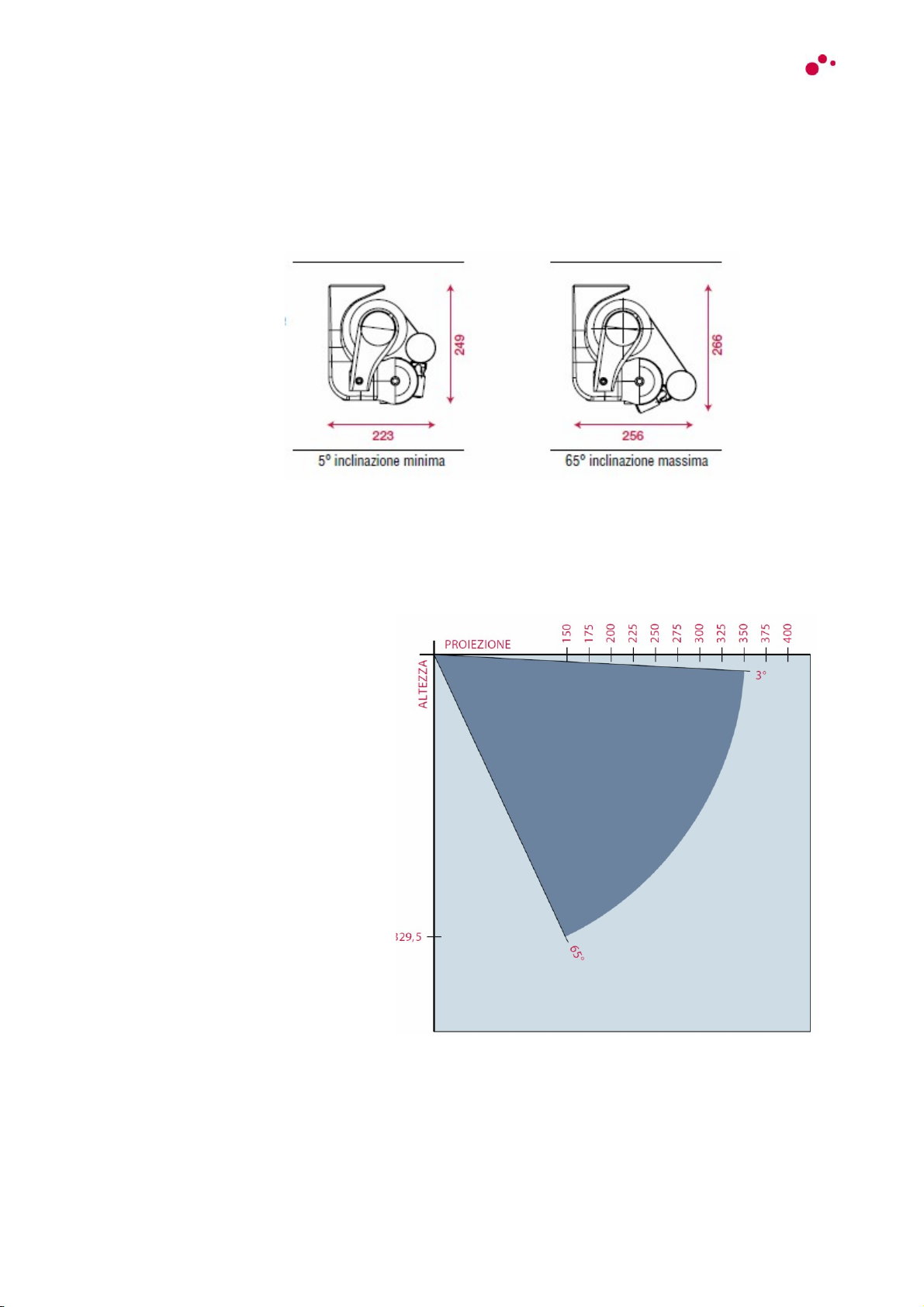
3 - KLIP COMPONENTS AND DIAGRAMS
3.1 Tilting diagrams
Awning dimensions with folded arms
Arm length and inclination
RECOMMENDED ARM: HOME
RECOMMENDED DIMENSIONS: width 600 cm - projection 350 cm

7I KLIP I INSTALLATION – REV 00
!
!
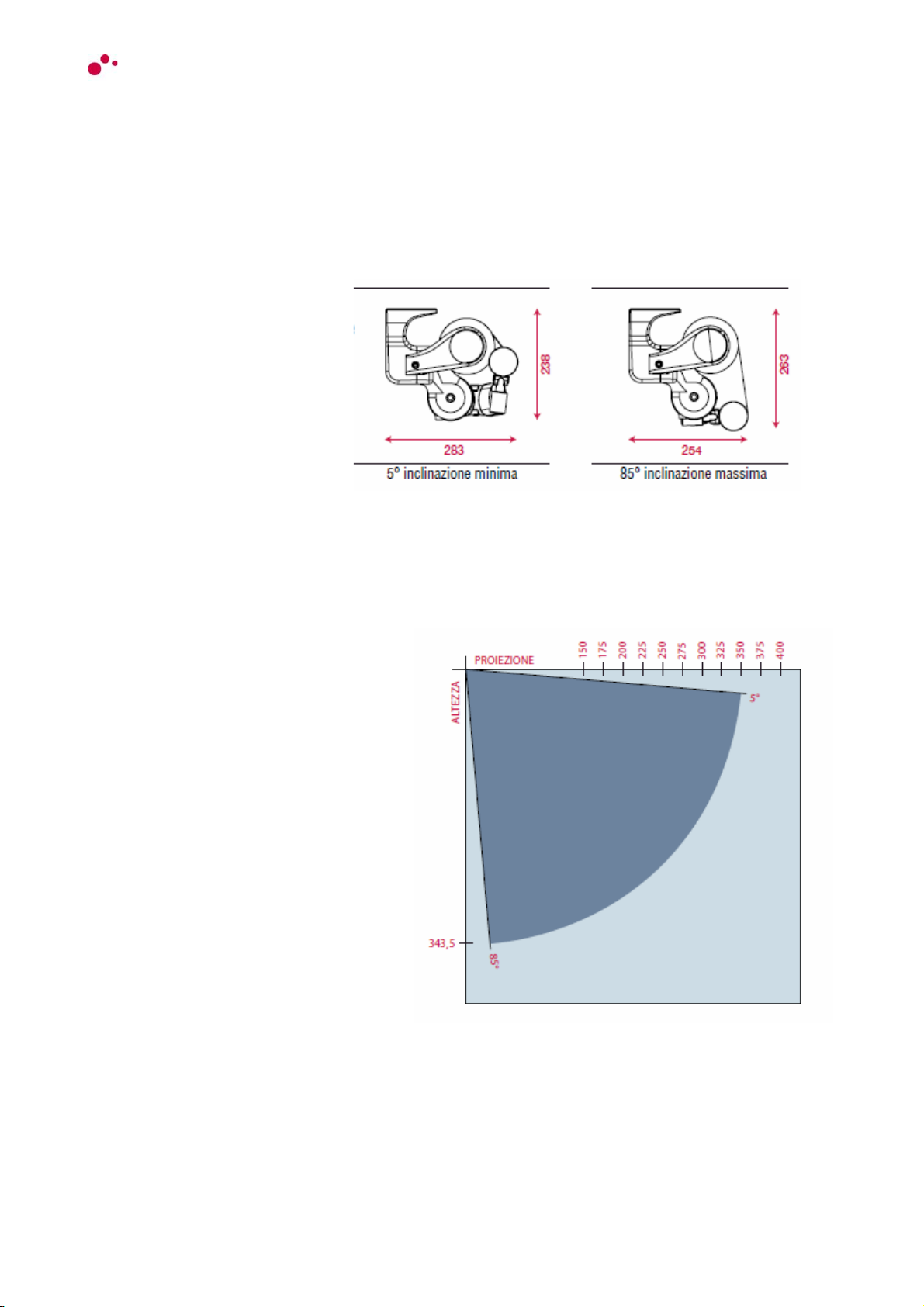
4 - KLIP XL COMPONENTS AND DIAGRAMS
4.1 Tilting diagrams
Awning dimensions with folded arms
Arm length and inclination
RECOMMENDED ARM: URBAN
RECOMMENDED DIMENSIONS: width 600 cm - projection 400 cm

8I KLIP I INSTALLATION – REV 00
!
!
5 - INSTALLATION TABLES AND TECHNICAL DRAWINGS
KLIP fixing bracket
9I KLIP I INSTALLATION – REV 00
6 - STEIN COMPONENTS AND DIAGRAMS
!
!
6.1 Tilting diagrams
Awning dimensions with folded arms
Arm length and inclination
RECOMMENDED ARM: HOME
RECOMMENDED DIMENSIONS: width 600 cm - projection 350 cm

10I KLIP I INSTALLATION – REV 00
!
!
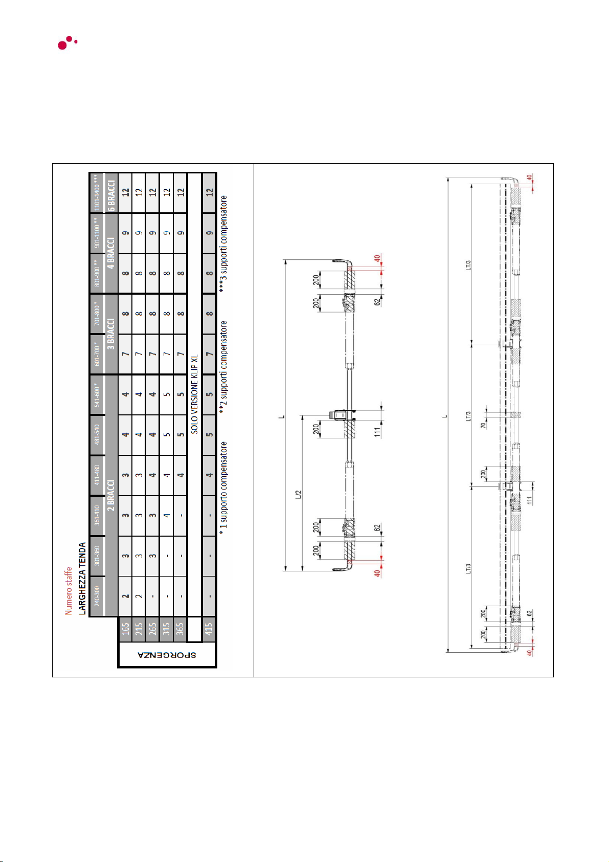
7 - INSTALLATION TABLES AND TECHNICAL DRAWINGS
STEIN fixing bracket
11I KLIP I INSTALLATION – REV 00
!
!
Quantity of brackets according to width and projection
WARNING: brackets must be positioned within the hatched areas; outer brackets must be at a
minimum distance of 40 mm from the edge of the square bar (not in the red hatching).
!
!
WARNING: Position and quantity of brackets depend on the awning width and projection.
WARNING: The brackets must be positioned within the hatched areas.
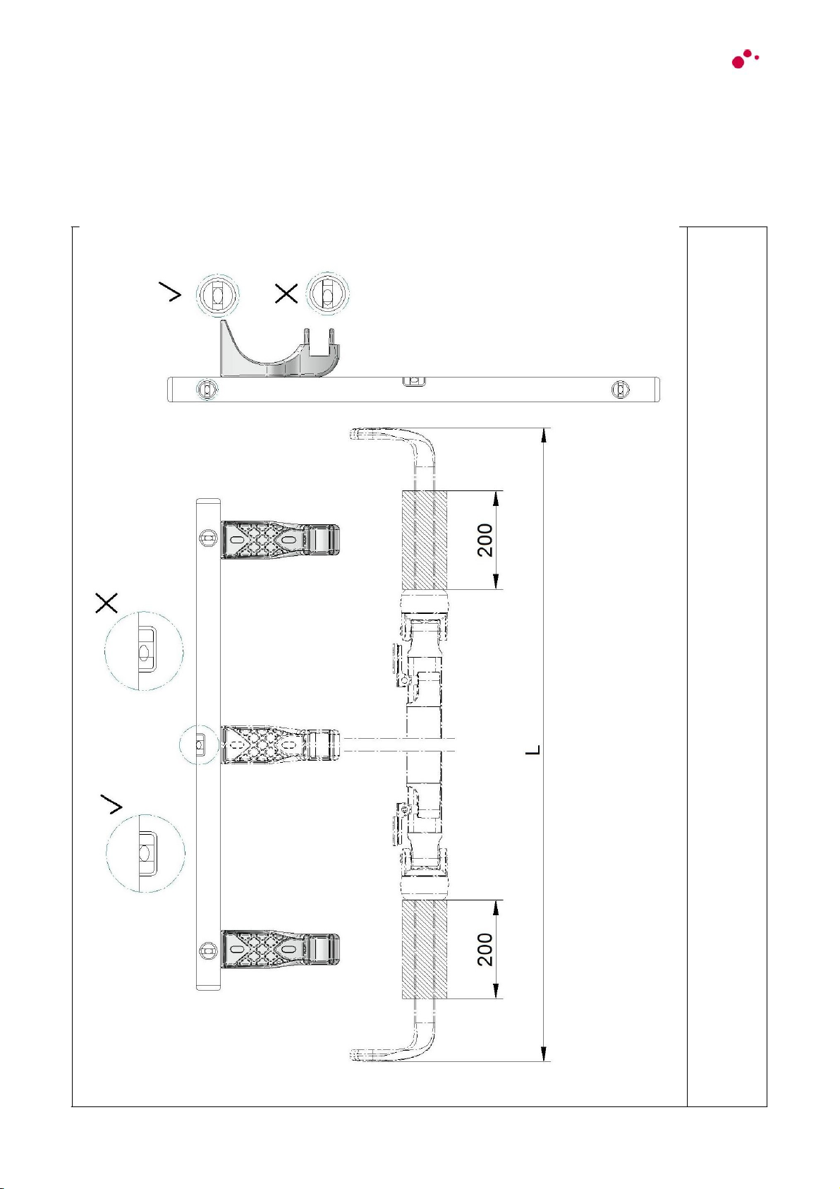
8 – KLIP and STEIN INSTALLATION
The images refer to the KLIP awning; STEIN is similar
Correct brackets position
12I KLIP I INSTALLATION – REV 00

!
!
WARNING: the quantity of brackets depends on the awning width.
WARNING: all brackets must be aligned
Brackets alignment
13 I KLIP I INSTALLATION – REV 00

14I KLIP I INSTALLATION – REV 00
!
!
Installation
WARNING: insert the square bar into the supporting brackets.
Close-up: fixing screw of the square bar awning
WARNING: secure the square bar by placing the screws as shown in figure (detail A)

15!I!KLIP!I!INSTALLATION!–!REV!00
!
!
Fitting caps to brackets
WARNING: after checking that the awning is firmly locked, cover the brackets with the caps (detail
B)
AWNING ADJUSTEMENT
WARNING: Ensure that no persons, animals or property are near the awning during
opening/closing operations.
Open and close the awning to check its correct operations.

16I KLIP I INSTALLATION – REV 00
Angle adjustment
!
!
WARNING:
Loosen the side screws (1) of the arm support (Allen wrench 10).
To increase the angle, loosen the socket-head cap screw (2) (Allen wrench 8).
To decrease the angle, tighten the socket-head cap screw, lifting the terminal bar accordingly.
After adjustment, check that the terminal bar is perfectly horizontal.
WARNING: after adjustment, firmly tighten screw 1
Adjusting arms alignment
WARNING: after adjusting the awning angle and the limit switch, check that the arms are parallel
when the awning is closed.
If they are not parallel, tighten or loosen the dowel (1) inside the lever (Allen wrench 3) supporting
the arm accordingly and adjust the alignment when the awning is closed.
17!I!KLIP!I!INSTALLATION!–!REV!00
!
!
COUPLED VERSION
The awning is supplied as shown in figure.
WARNING: The awning is delivered pre-assembled, as much as possible.
WARNING: Do not remove the arm lock.
Arm coupling
WARNING: in some cases arms must be coupled with the arm support.
Fit the arm on the lever by inserting the pin (detail C).
18I KLIP I INSTALLATION – REV 00
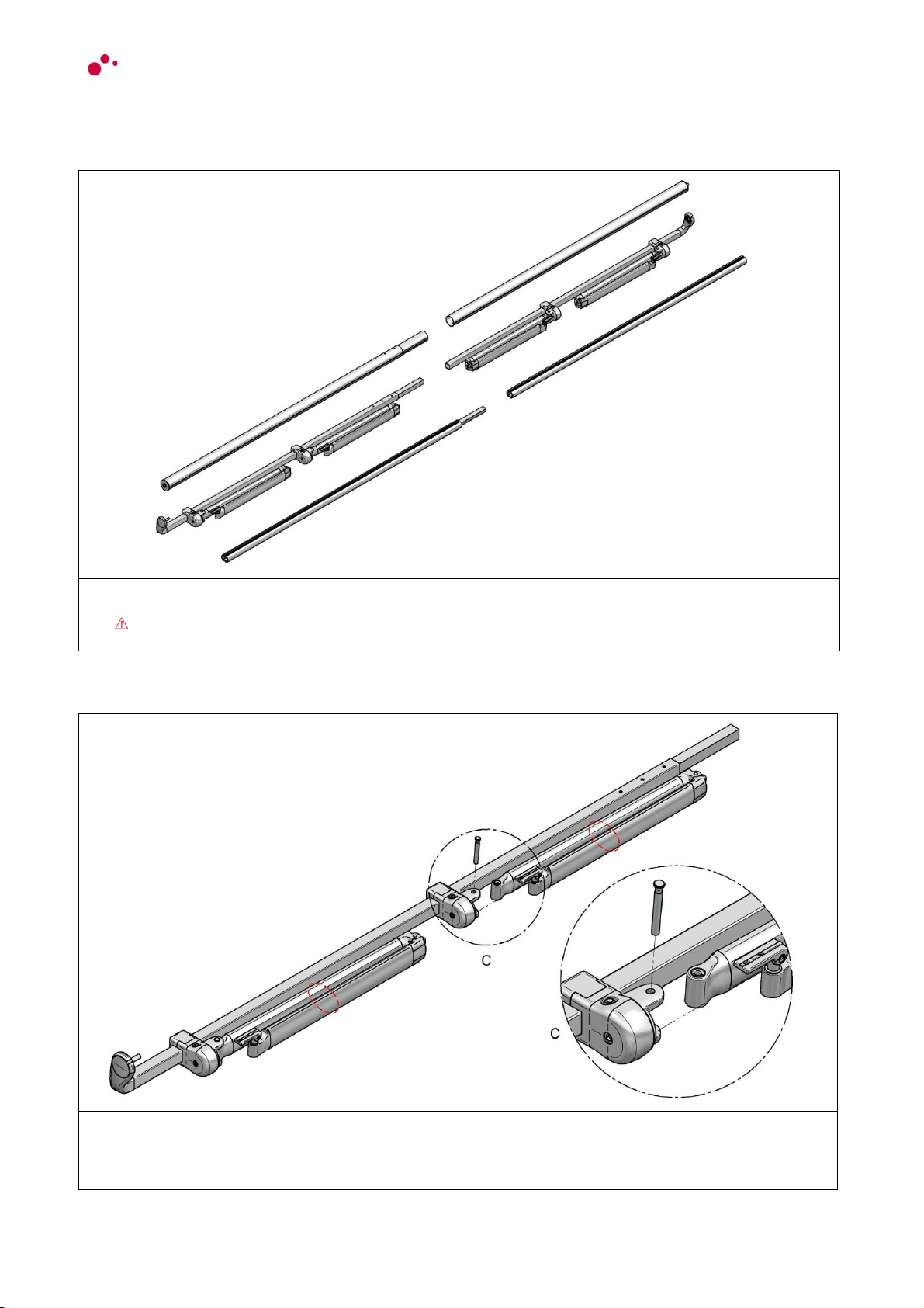
Roller tube coupling
!
!
WARNING:
Couple the tube by inserting it on the pre-assembled joint and secure using the rivets provided.
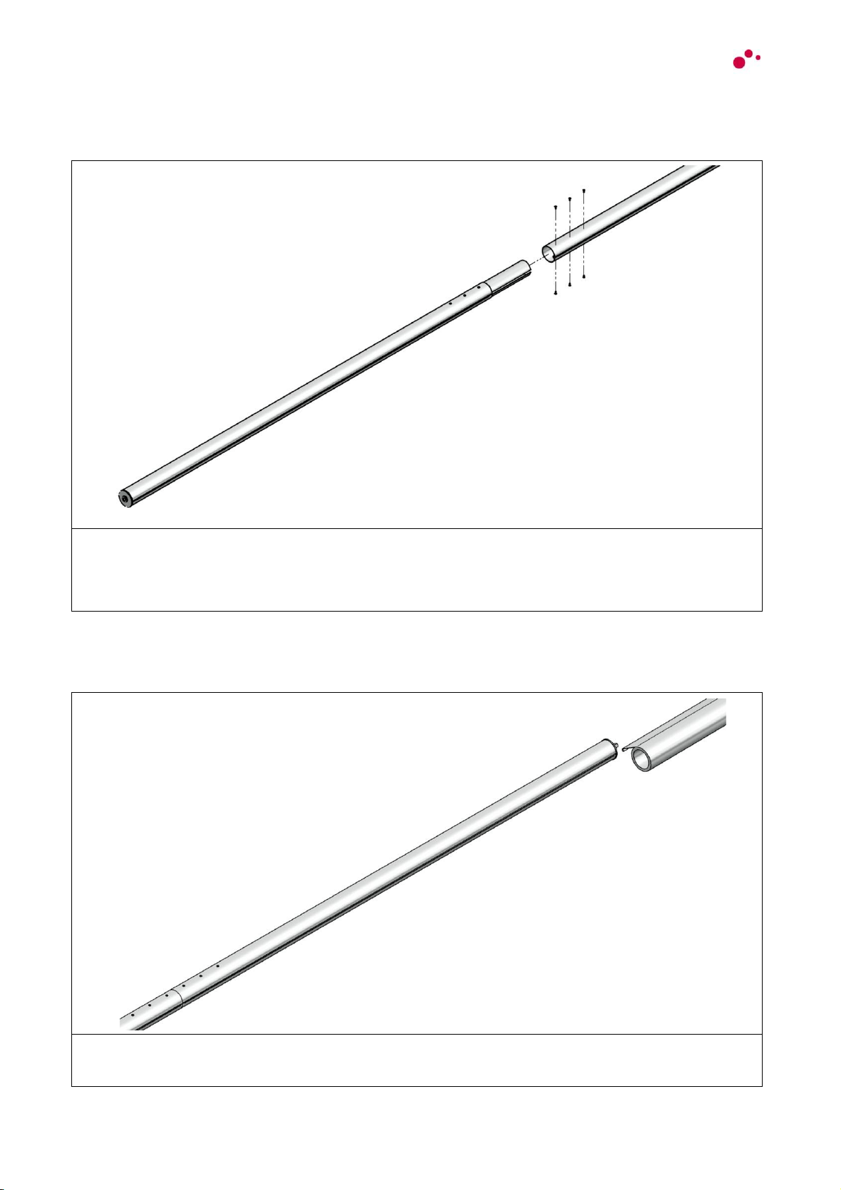
Fabric assembly
WARNING: slide the fabric into the tube, centre it, lock it and roll it up.
This manual suits for next models
1
Table of contents
Other ShadeLab Tent manuals


