Shangzhadyuan H97 STRONG User manual


Any problem, please feel free to contact us.
Contents
Specifications............................................................................................................ 1
Overview of Components.....................................................................................2
Install CPU & Fan..................................................................................................... 3
Install Memory.........................................................................................................4
Install Expansion Card..............................................................................................5
Back Panel Connectors............................................................................................ 5
USB 2.0 Port......................................................................................................5
USB 3.0 Port......................................................................................................5
VGA Port........................................................................................................... 5
Display Port.......................................................................................................6
HDMI Port......................................................................................................... 6
RJ45 LAN Port................................................................................................... 6
PS/2 Port...........................................................................................................6
Audio Port.........................................................................................................6
Internal Connectors................................................................................................. 8
F_PANEL1 Connector........................................................................................ 8
SPEAK1 Connector............................................................................................ 8
JAUDIO1 Connector.......................................................................................... 8
SATA1~4: SATA 3.0 Connectors..........................................................................9
M.2 Slot.............................................................................................................9
JCMOS1: CMOS Discharge.............................................................................. 10
ATXPWR1, JATXPWR1: Power Connectors...................................................... 11
CPU_FAN1, SYS_FAN1: Fan Connectors.......................................................... 12
JUSB2: USB 2.0 Connector.............................................................................. 12
FUSB3: USB 3.0 Connector............................................................................. 12
BIOS Setup................................................................................................................13
BIOS Setup............................................................................................................. 13
Enter BIOS Setup....................................................................................................14
Reset BIOS..............................................................................................................14
Any problem, please feel free to contact us.
1
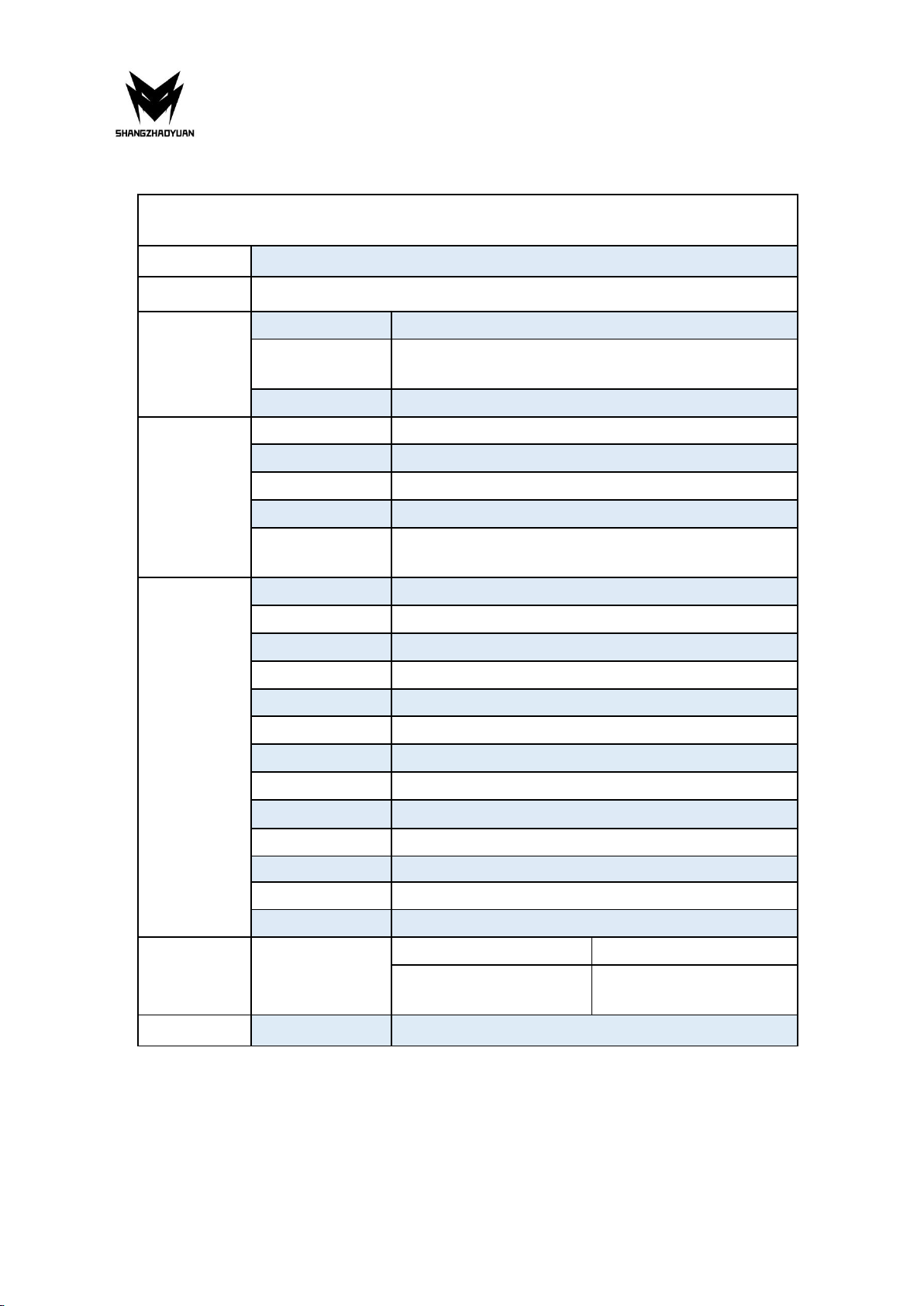
Specifications
H97 STRONG
Processor
Intel Core i7 i5 i3 lga 1150 pin series processor
Southbridge
H97 Chipset
RAM
Technology
Dual channel DDR3
Maximum
Capacity
32GB (16GB*2)
Memory Slot
2 * DDR3
Rear I/O
PS/2
1 * KB/MS Interface
Display Interface
1 * HDMI; 1 * VGA; 1 * DP
USB
4 * USB 2.0;2 * USB3.0
Ethernet
2 * Gigabit LAN Card
AUDIO
1 (Mic-in, Line-out, Line-in, rear speaker out,
center/subwoofer out, side speaker out)
Internal
connector
CFAN
1 * 4PIN
SFAN
1 * 3PIN
ATXPWR Interface
1 * 8PIN Power Socket;1 * 24PIN Power Socket
USB2.0
1
USB3.0
1
M.2
1 (NVME M.2)
WIFI M.2
1
JSPEAK1
1
SATA Interface
4 (4 * SATA3.0)
JAUDIO
1 * 2x5Pin
JLPC1
1
JME1
1
PCIe
1 * PCIe x16
Environment
Temperature
Range
Working Environment
Storage Environment
Temperature:0~50°C
Humidity:5%~95%
Temperature: -20~70°C
Humidity: 5%~95%
Physical Size
Size
170mm*170mm

Any problem, please feel free to contact us.
2
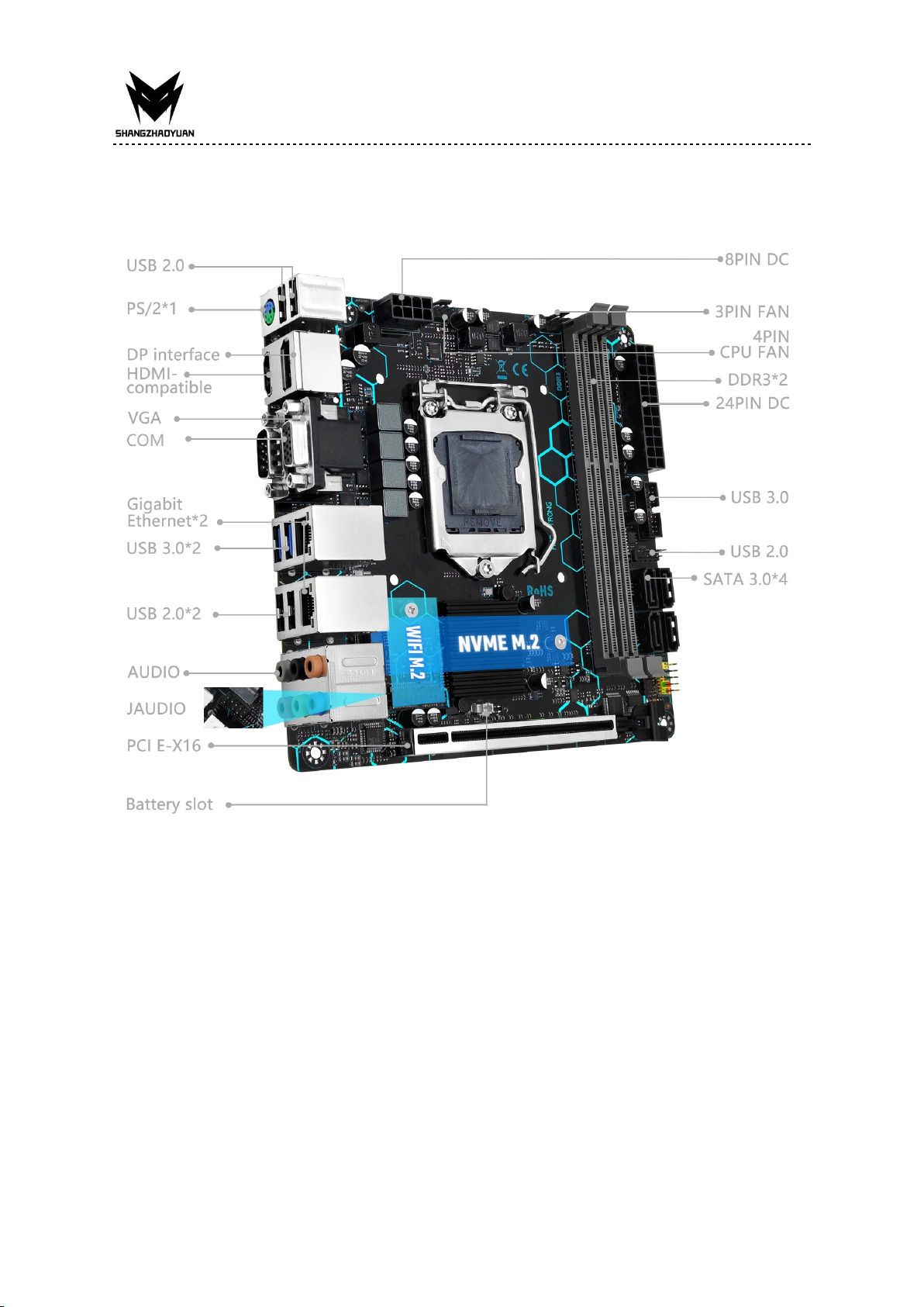
Overview of Components
Package List:
H97 STRONG Motherboard * 1
SATA Cable * 1
I/O Blocking * 1
Any problem, please feel free to contact us.
3
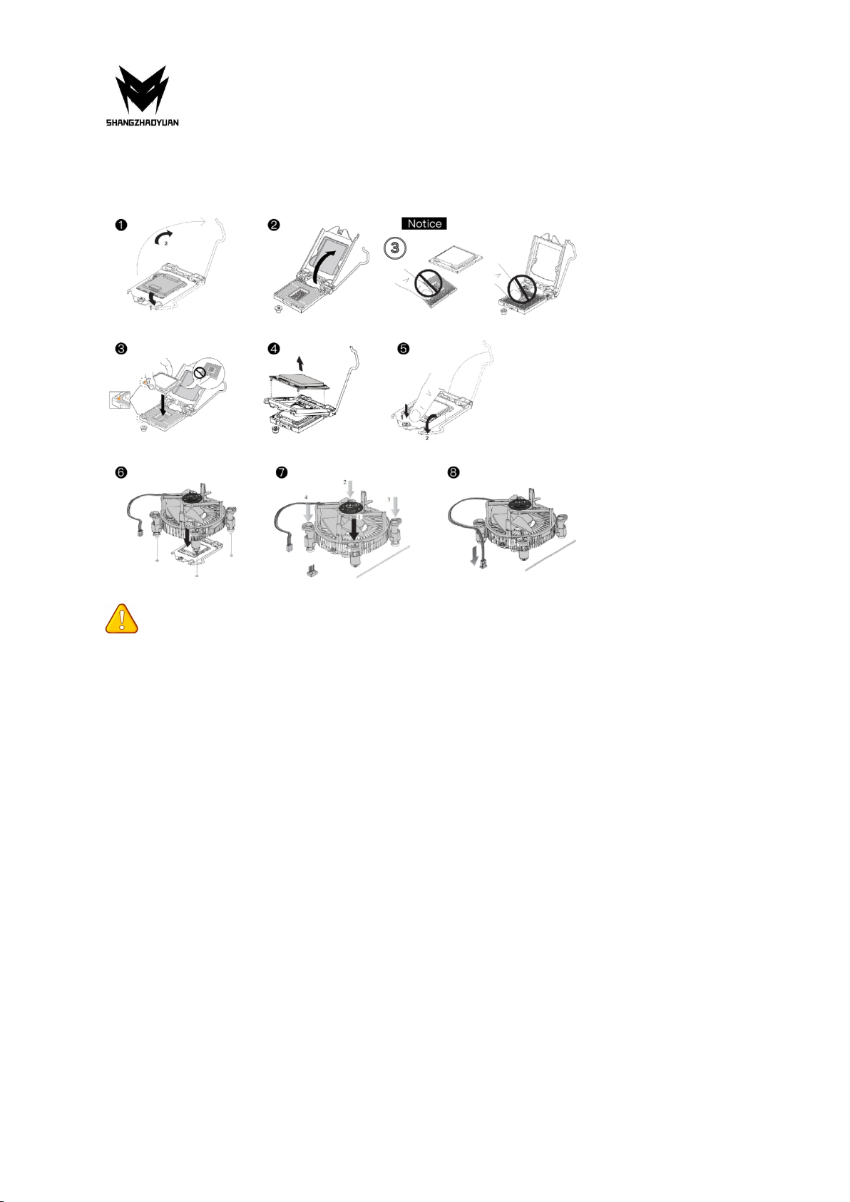
Install CPU & Fan
Please install the CPU into the CPU socket (LGA 1150) as shown below.
Important
• Make sure that the motherboard supports the CPU.
• Always unplug the power cord from the power outlet before installing or removing the
CPU to prevent hardware damage.
• Please retain the CPU protective cap after installing the processor.
• Do not turn on the computer if the CPU cooler is not installed, otherwise overheating and
damage to the CPU may occur.
• Confirm that the CPU heatsink has formed a tight seal with the CPU before booting your
system.
• Apply an even layer of thermal paste (or thermal tape) between the CPU and the heatsink
to enhance heat dissipation.
• Whenever the CPU is not installed, always protect the CPU socket pins by covering the
socket with a plastic cap.
• Locate the pin one of the CPU socket and the CPU. Once the CPU is 00positioned into its
socket, place one finger down on the middle of the CPU, lowering the locking lever and
latching it into the fully locked position.
• Do not force the CPU into the CPU socket before the CPU socket locking lever is lifted up,
or damage to the CPU and CPU socket may occur.
• Connect the CPU heatsink's 4pin fan power connector to the 4pin CPU fan header on the
motherboard.
• Please be sure to plug in the 8-PIN power supply to power the CPU.

Any problem, please feel free to contact us.
4
Install Memory
The motherboard provides 2 DDR3 DIMM slots, each with a maximum capacity of 16GB.
1. Wrench the latches on both sides of the memory slot outwards.
2. Insert the memory into the slot by aligning it with the notch in the slot.
3. Flip the latches on both sides of the slot to lock the memory.
Important
• Make sure that the motherboard supports the memory. It is recommended that memory
of the same capacity, brand, speed, and chips be used.
• Always turn off the computer and unplug the power cord from the power outlet before
installing the memory to prevent hardware damage.
• Memory modules have a foolproof design. A memory module can be installed in only one
direction. If you are unable to insert the memory, switch the direction.
• The stability and compatibility of the installed memory module depend on the installed
CPU and devices when overclocking.
• This motherboard provides two memory sockets and supports Dual Channel Technology.
Dual-Channel mode cannot be enabled if only one memory module is installed.
Any problem, please feel free to contact us.
5
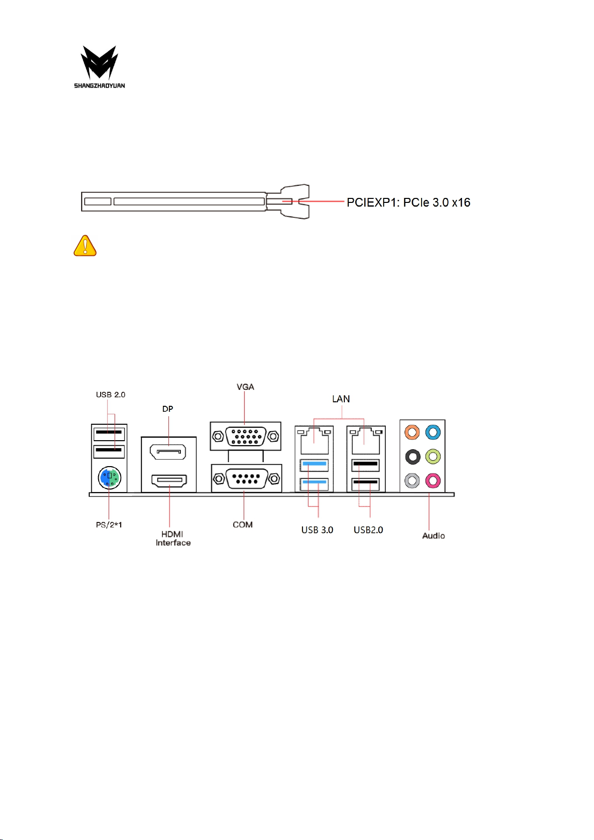
Install Expansion Card
The motherboard provides a PCI Express 3.0 x16 expansion slot.
Place the expansion card in an available PCI Express slot and press the expansion card until it
is fully inserted into the slot.
Important
• When adding or removing expansion cards, always turn off the power supply and unplug
the power supply power cable from the power outlet to prevent hardware damage.
• If the expansion card is not installed correctly, it may cause a short circuit throughout the
metal pins, which could burn out the expansion card or the motherboard.
Back Panel Connectors
USB 2.0 Port
The USB port supports the USB 2.0 specification. Use this port for USB devices.
USB 3.0 Port
The USB 3.0 supports the USB 3.0 specification and is compatible to the USB 2.0
specification. Use this port for USB devices.
VGA Port
VGA (Video Graphics Array) supports analog video signal transmission, high resolution, fast
display rate and rich colors.
Any problem, please feel free to contact us.
6
Display Port
DisplayPort (DP) delivers high-quality digital imaging and audio. You can use this port to
connect your DisplayPort-supported monitor.
HDMI Port
The HDMI port supports 4K and 1080px. You can use this port to connect your
HDMI-supported monitor.
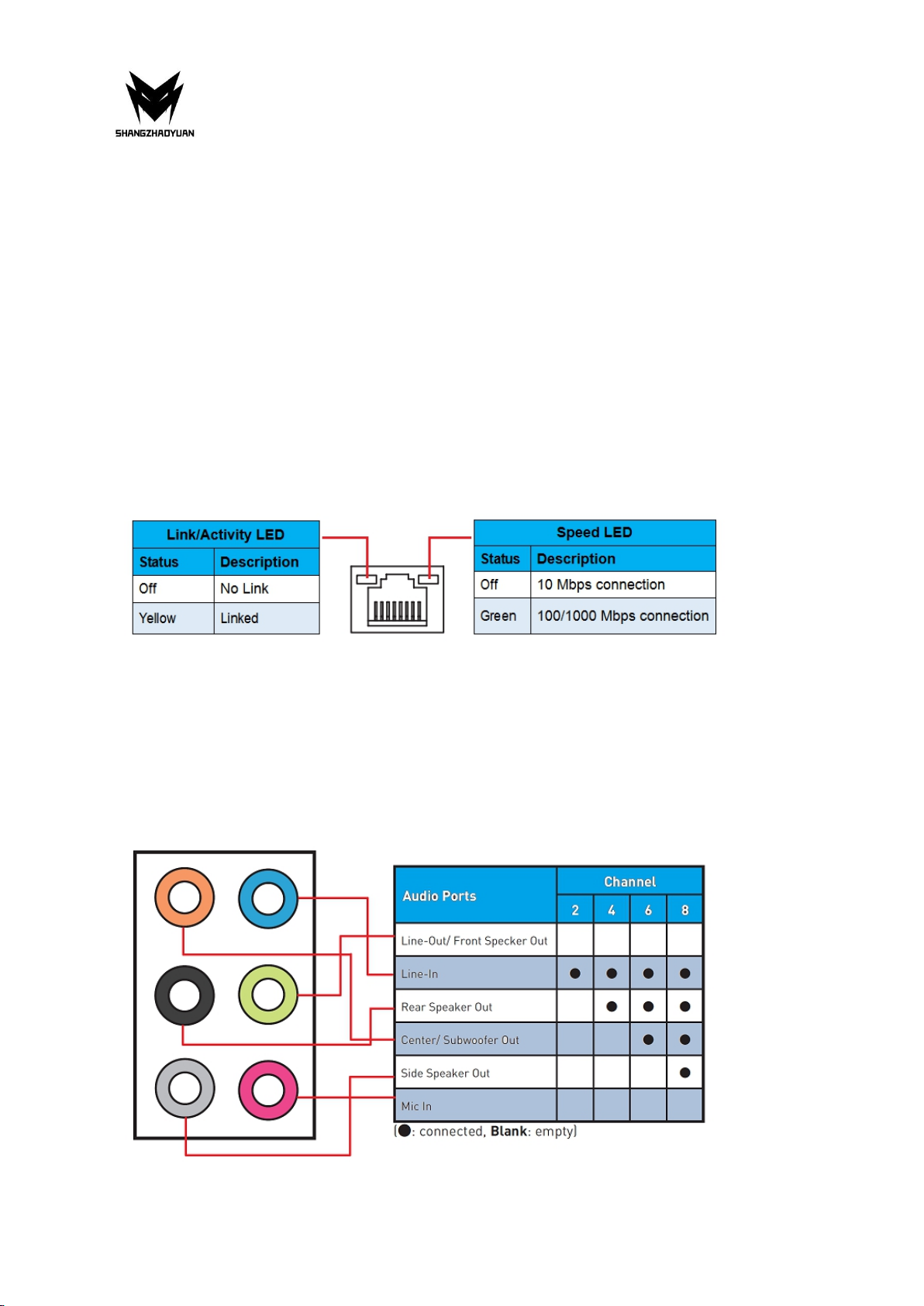
RJ45 LAN Port
The Gigabit Ethernet LAN port provides Internet connection at up to 1000Mbps/s data rate.
The following describes the states of the LAN port LEDs.
PS/2 Port
This PS/2 port can be connected to a keyboard or mouse.
Audio Port

Any problem, please feel free to contact us.
7
Line In/Side Speaker Out
The line in Jack. Use this audio jack for line-in devices such as an optical drive, walkman, etc.
Line Out/Front Speaker Out
The line out Jack.
Mic In/Side Speaker Out
The Mic in Jack.
Center/Subwoofer Speaker Out
Use this audio jack to connect the rear speakers.
Rear Speaker Out
Use this audio jack to connect the rear speakers.
Optical S/PDIF Out Connector
This connector provides digital audio out to an external audio system that supports digital
optical audio.
Before using this feature ensure that your audio system provides optical digital audio in the
connector.

Any problem, please feel free to contact us.
8
Internal Connectors
F_PANEL1 Connector
SPEAK1 Connector
JAUDIO1 Connector
This connector allows you to connect audio jacks on the front panel.
Important
• An incorrect connection between the module connector and the motherboard header will
make the device unable to work or even damage it.
Any problem, please feel free to contact us.
9
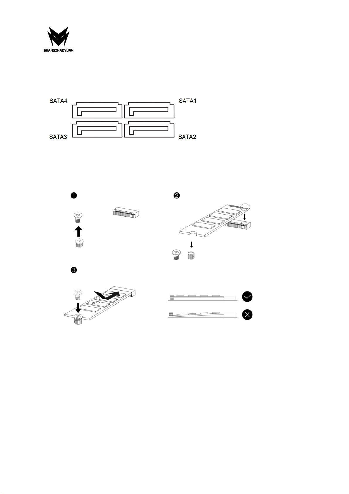
SATA1~4: SATA 3.0 Connectors
These SATA 3.0 connectors are SATA 6Gb/s interface ports. Each SATA connector supports a
single SATA device.
M.2 Slot
Insert your M.2 SSD into the M.2 slot at a 30-degree angle. Secure the M.2 SSD in place with
the scr ew.
Any problem, please feel free to contact us.
10
WLAN-1 Slot
The M.2 WiFi interface, which is compatible with WiFi AC standard expansion cards, can be
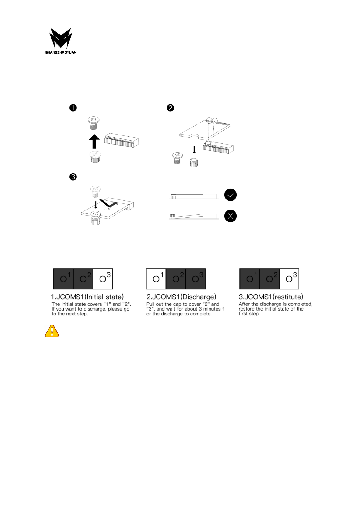
used after the M.2 WiFi module is installed and the corresponding driver is loaded.
JCMOS1: CMOS Discharge
Important
• Always turn off the computer and unplug the power cord from the power outlet before
discharging.
Any problem, please feel free to contact us.
11
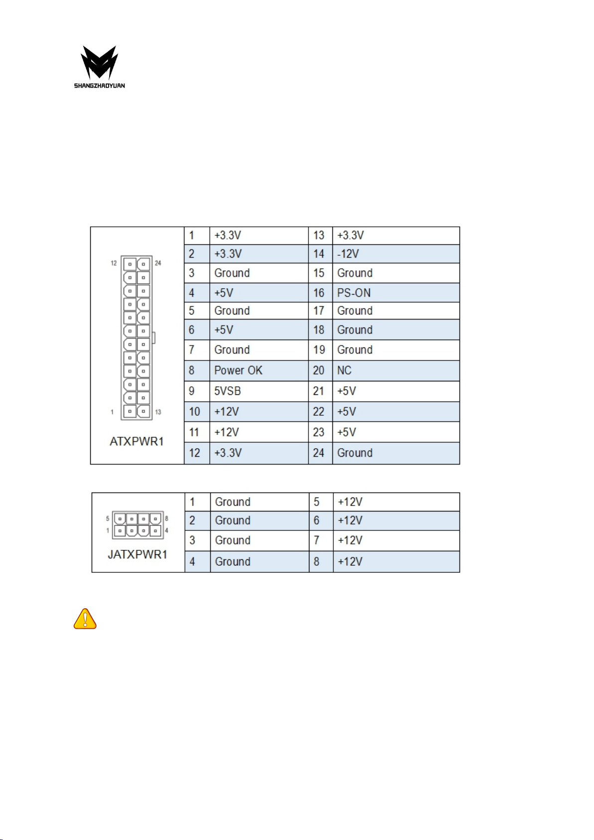
ATXPWR1, JATXPWR1: Power Connectors
With the use of the power connector, the power supply can provide enough stable power to
all the components on the motherboard. Before connecting the power connector, make sure
the power supply is turned off and all devices are properly installed.
24PIN for motherboard power supply.
8PIN for CPU power supply.
Important
• It is recommended that a power supply that can withstand high power consumption be
used (at least 500W). If a power supply is used that does not provide the required power,
the result can lead to an unstable or unbootable system.
Any problem, please feel free to contact us.
12
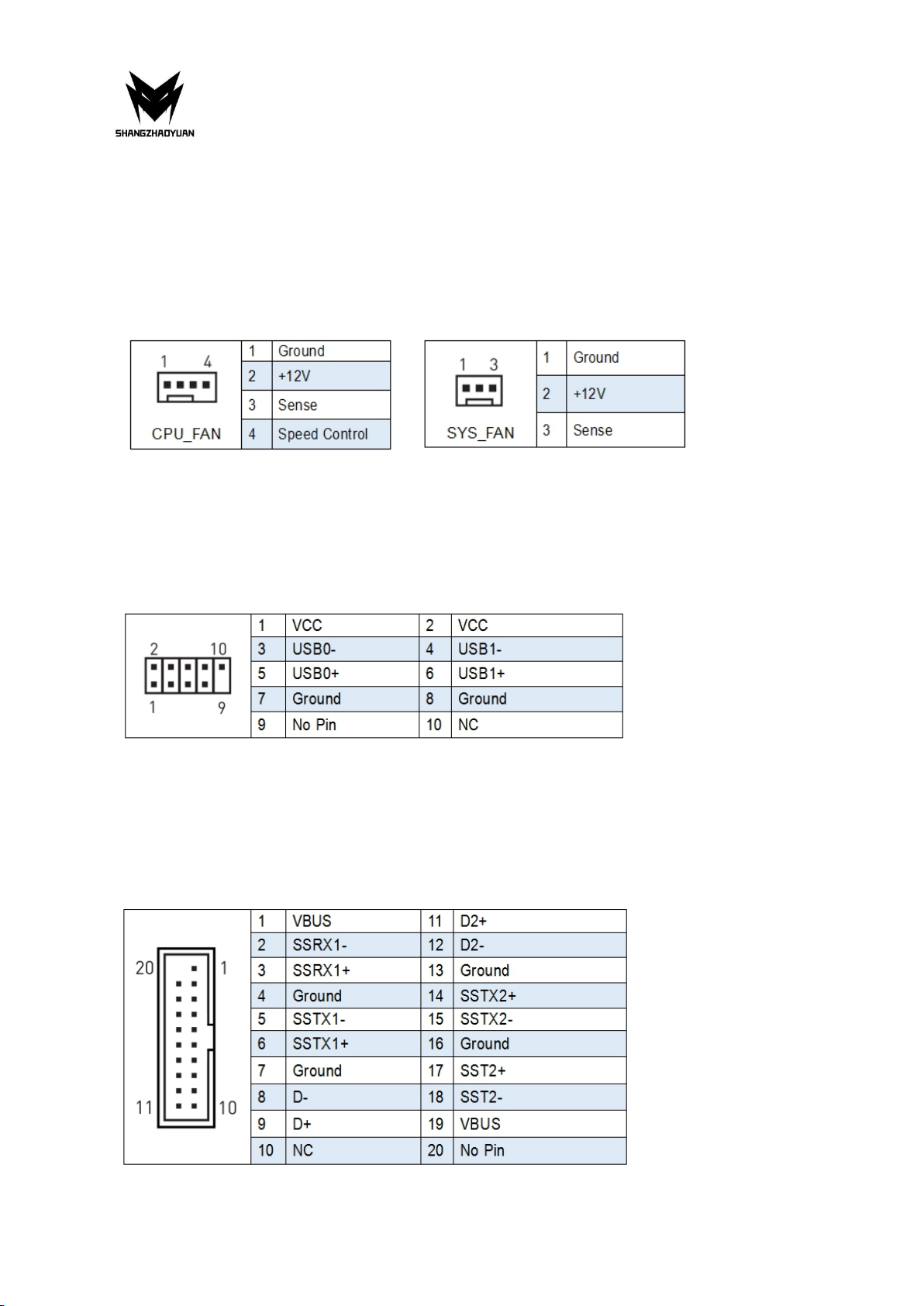
CPU_FAN1, SYS_FAN1: Fan Connectors
CPU_FAN is a interface for CPU radiator. The 4pin fan has PWM intelligent speed regulation
function, which can intelligently control the fan speed based on load and temperature
changes.
SYS_FAN is the system cooling fan interface, which is generally connected to the case fan.
The 3pin fan has no PWM adjustment capability.
JUSB2: USB 2.0 Connector
The headers conform to USB 2.0 specification. This connector allows you to connect USB 2.0
ports on the front panel.
FUSB3: USB 3.0 Connector
The header conforms to USB 3.0 and USB 2.0 specification. This connector allows you to
connect USB 3.0 ports on the front panel.

Any problem, please feel free to contact us.
13
BIOS Setup
BIOS (Basic Input and Output System) records hardware parameters of the system in the
CMOS on the motherboard. BIOS identifies, configures, tests and connects computer
hardware to the OS immediately after a computer is turned on.
Its major functions include conducting the Power-On Self-Test (POST) during system startup,
saving system parameters and loading the operating system, etc. BIOS includes a BIOS Setup
program that allows the user to modify basic system configuration settings or to activate
certain system features.
When the power is turned off, the battery on the motherboard supplies the necessary
power to the CMOS to keep the configuration values in the CMOS.
Important
• Because BIOS flashing is potentially risky if you do not encounter problems using the
current version of BIOS, it is recommended that you not flash the BIOS. To flash the BIOS, do
it with caution. Inadequate BIOS flashing may result in system malfunction.
BIOS Setup
The default settings offer the optimal performance for system stability in normal conditions.
It is recommended that you not alter the default settings (unless you need to) to prevent
system instability or other unexpected results. Inadequately altering the settings may result
in the system's failure to boot.
Important
• BIOS items are regularly updated for better system performance. The items may be slightly
different from the latest BIOS; therefore, the description is for reference only.
Any problem, please feel free to contact us.
14
Enter BIOS Setup
Entering BIOS Setup
When the computer starts up, BIOS enters the self-test process. When the self-test is
completed, the following message is displayed: Press DEL key to enter Setup Menu. At this
time, Press <Delete> key to enter the BIOS setup.
If this message disappears before you press <DEL> key, you can turn it off and then turn on
your computer or press <Reset> on the case to restart your computer. You can also press
<Ctrl>+<Alt>+<Delete> at the same time to restart your computer.
Important
• Functions may vary depending on the product you have.
Reset BIOS
When you need to restore the default BIOS settings to resolve certain issues, there are
several ways to reset the BIOS:
∙ Go to BIOS and press F6 to load optimized defaults.
∙ Short the Clear CMOS jumper on the motherboard.
Important
• Be sure the computer is off before clearing CMOS data. Please refer to the Clear CMOS
jumper section for resetting BIOS.


Any problem, please feel free to contact us.
Inhalt
Spezifikationen......................................................................................................... 1
Übersicht der Komponenten...............................................................................2
Installieren Sie CPU und Lüfter................................................................................ 3
Arbeitsspeicher installieren..................................................................................... 4
Erweiterungskarte installieren.................................................................................5
Anschlüsse auf der Rückseite.................................................................................. 5
USB 2.0-Anschluss.............................................................................................5
USB 3.0-Anschluss.............................................................................................5
VGA-Anschluss.................................................................................................. 5
DP-Schnittstelle.................................................................................................6
HDMI-Anschluss................................................................................................6
RJ45-LAN-Anschluss..........................................................................................6
PS/2-Anschluss................................................................................................. 6
Audio-Port.........................................................................................................6
Interne Anschlüsse...................................................................................................8
F_PANEL1-Anschluss.........................................................................................8
SPEAK1-Anschluss.............................................................................................8
JAUDIO1-Anschluss........................................................................................... 8
SATA1~4: SATA 3.0 Connectors..........................................................................9
M.2-Steckplatz.................................................................................................. 9
WLAN-1 Slot....................................................................................................10
JCMOS1: CMOS-Entladung............................................................................. 10
ATXPWR1, JATXPWR1: Stromanschlüsse.........................................................11
CPU_FAN1, SYS_FAN1: Lüfteranschlüsse........................................................ 12
JUSB2: USB 2.0-Anschlüsse.............................................................................12
FUSB3: USB 3.0-Anschluss.............................................................................. 12
BIOS-Setup............................................................................................................... 13
BIOS-Setup.............................................................................................................13
Rufen Sie das BIOS-Setup auf.................................................................................14
BIOS zurücksetzen..................................................................................................................... 14

Any problem, please feel free to contact us.
1
Spezifikationen
H97 STRONG
Prozessor
Intel Core i7 i5 i3 lga 1150-Pin-Prozessor
Südbrücke
H97-Chipsatz
RAM
Technologie
Dual-Channel-DDR3
Maximale Kapazität
32 GB (16 GB*2)
Speichersteckplatz
2 * DDR3
E/A
hinten
PS/2
1 * KB/MS-Schnittstelle
Anzeigeschnittstelle
1 x HDMI; 1 x VGA; 1 * DP
USB
4 * USB 2.0; 2 * USB 3.0
Ethernet
2 * Gigabit-LAN-Karte
AUDIO
1 (Mic-in, Line-out, Line-in, hinterer Lautsprecherausgang,
Center/Subwoofer-Ausgang, seitlicher
Lautsprecherausgang)
Interner
Anschluss
CFAN
1 * 4 PIN
SFAN
1 * 3 PIN
ATXPWR-Schnittstel
le
1 * 8-PIN-Steckdose; 1 * 24-PIN-Steckdose
USB2.0
1
USB3.0
1
M.2
1 (NVME-M.2)
WLAN M.2
1
JSPEAK1
1
SATA-Schnittstelle
4 (4 * SATA3.0)
JAUDIO
1 * 2x5Pin
JLPC1
1
JME1
1
PCIe
1 * PCIe-x16
Umfeld
Temperaturbereich
Arbeitsumfeld
Speicherumgebung
Temperatur: 0 ~ 50 ° C
Luftfeuchtigkeit: 5 % ~ 95 %
Temperatur: -20~70 °C
Luftfeuchtigkeit: 5 % ~ 95 %
Physische
Größe
Size
170mm*170mm
Any problem, please feel free to contact us.
2
Übersicht der Komponenten
Paketliste:
H97 STRONG Mainboard* 1
SATA-Kabel * 1
E/A-Blockierung * 1
Table of contents
Languages:
Other Shangzhadyuan Motherboard manuals


