Shangzhadyuan BTC-B250C User manual


Any problem, please feel free to contact us.
Contents
Specifications...........................................................................................................1
Overview of Components...................................................................................2
Install CPU & Fan ....................................................................................................3
Install Memory ....................................................................................................... 4
Back Panel Connectors...........................................................................................5
USB 2.0 Port..................................................................................................... 5
USB 3.0 Port..................................................................................................... 5
VGA Port...........................................................................................................5
HDMI Port........................................................................................................ 5
RJ45 LAN Port...................................................................................................5
PS/2 Port.......................................................................................................... 5
Internal Connectors ................................................................................................6
F_PANEL1 Connector ....................................................................................... 6
SPEAK1 Connector ........................................................................................... 6
4*SATA 2.0 Connectors.................................................................................... 6
MSATA Slot ....................................................................................................... 7
JCMOS1: CMOS Discharge ............................................................................... 7
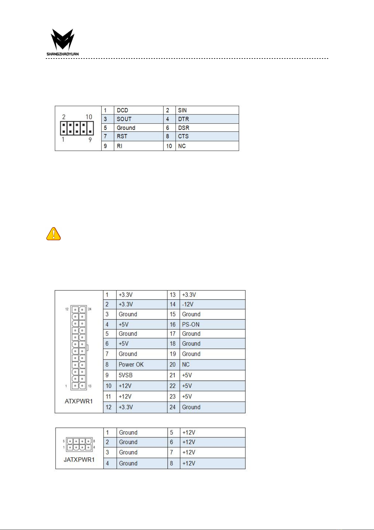
JCOM1: Serial Port Connector ......................................................................... 8
ATXPWR1, JATXPWR1: Power Connectors ....................................................... 8
CPU_FAN1, SYS_FAN1: Fan Connectors........................................................... 9
FUSB1~2: USB 2.0 Connectors......................................................................... 9
USB30_1: USB 3.0 Connector.......................................................................... 9
BIOS Setup.............................................................................................................. 10
BIOS Setup ............................................................................................................ 10
Enter BIOS Setup .................................................................................................. 10
Reset BIOS............................................................................................................ 11
Any problem, please feel free to contact us.
1
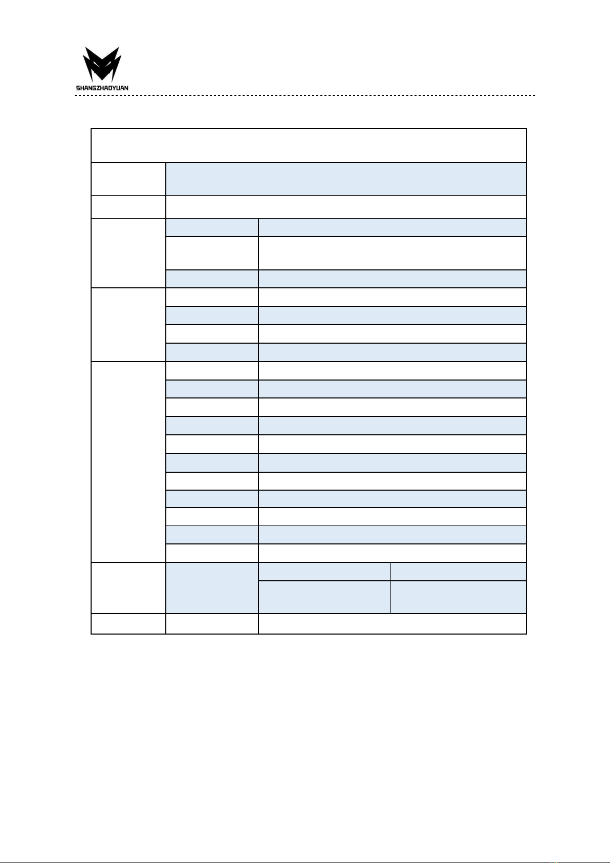
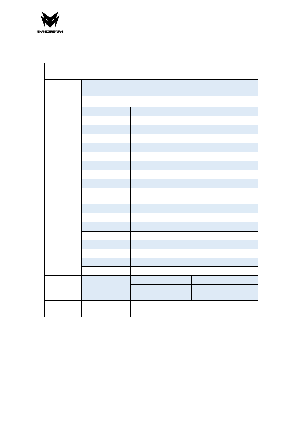
Specifications
BTC B250C
Processor
Support Intel 6th/7th Gen Core i3/i5/i7 (Intel Skylake full series), Xeon E3
1230 V5, Celeron and Pentium series processors.
Southbridge
B250 Chipset
RAM
Technology
Dual channel DDR4
Maximum
Capacity
32GB (16GB*2)
Memory Slot
2 * DDR4
Rear I/O
PS/2
2 (Green: mouse, Purple: keyboard)
Display Interface
1 * HDMI, 1 * VGA
USB
2 * USB 2.0, 2 * USB 3.0
Ethernet
1 * Gigabit LAN
Internal
connector
CFAN
1 * 4PIN
SFAN
1 * 4PIN
ATXPWR Interface
24+4+6PIN Power Socket
USB2.0(front)
2
USB3.0(front)
1
MSATA
1
SATA Interface
4 * SATA 2.0
JPSON
1
SPEAK1
1
JCMOS Port
1
PCIe
0
Environment
Temperature
Range
Working Environment
Storage Environment
Temperature:0~50°C
Humidity:5%~95%
Temperature: -20~70°C
Humidity: 5%~95%
Physical Size
Size
175*230 mm
Any problem, please feel free to contact us.
2
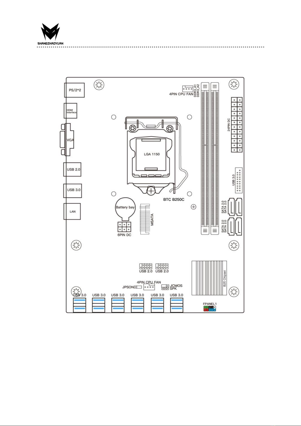
Overview of Components
Package List:
BTC B250C Motherboard * 1
SATA Cable * 1
Any problem, please feel free to contact us.
3
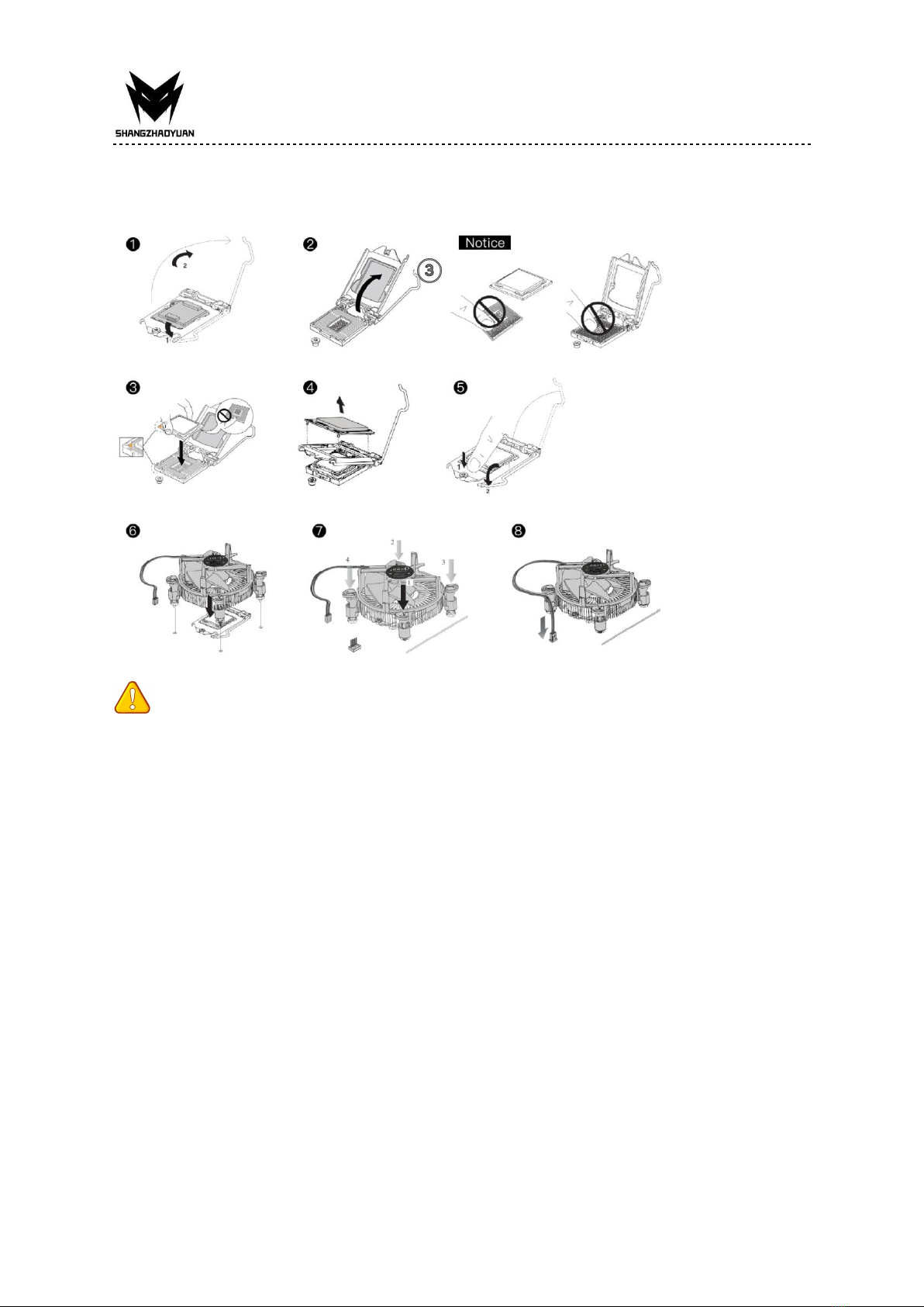
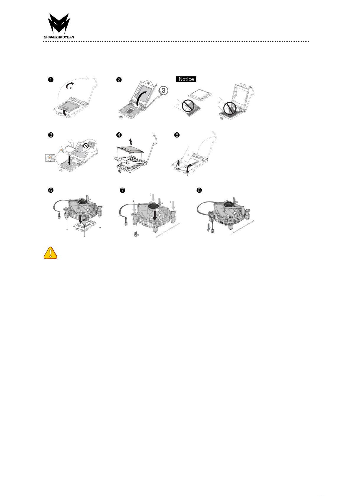
Install CPU & Fan
Please install the CPU into the CPU socket (LGA 1151) as shown below.
Wichtig
• Make sure that the motherboard supports the CPU.
• Always unplug the power cord from the power outlet before installing or removing the
CPU to prevent hardware damage.
• Please retain the CPU protective cap after installing the processor.
• Do not turn on the computer if the CPU cooler is not installed, otherwise overheating and
damage to the CPU may occur.
• Confirm that the CPU heatsink has formed a tight seal with the CPU before booting your
system.
• Apply an even layer of thermal paste (or thermal tape) between the CPU and the heatsink
to enhance heat dissipation.
• Whenever the CPU is not installed, always protect the CPU socket pins by covering the
socket with a plastic cap.
• Locate the pin one of the CPU socket and the CPU. Once the CPU is positioned into its
socket, place one finger down on the middle of the CPU, lowering the locking lever and
latching it into the fully locked position.
• Do not force the CPU into the CPU socket before the CPU socket locking lever is lifted up,
or damage to the CPU and CPU socket may occur.
• Connect the CPU heatsink's 4pin fan power connector to the 4pin CPU fan header on the
motherboard.

Any problem, please feel free to contact us.
4
Install Memory
The motherboard provides 2 DDR4 DIMM slots with a maximum capacity of 32GB.
1. Wrench the latches on both sides of the memory slot outwards.
2. Insert the memory into the slot by aligning it with the notch in the slot.
3. Flip the latches on both sides of the slot to lock the memory.
Wichtig
• Make sure that the motherboard supports the memory. It is recommended that memory
of the same capacity, brand, speed, and chips be used.
• Always turn off the computer and unplug the power cord from the power outlet before
installing the memory to prevent hardware damage.
• Memory modules have a foolproof design. A memory module can be installed in only one
direction. If you are unable to insert the memory, switch the direction.
• The stability and compatibility of the installed memory module depend on the installed
CPU and devices when overclocking.
• This motherboard provides two memory sockets and supports Dual Channel Technology.
Dual-Channel mode cannot be enabled if only one memory module is installed.

Any problem, please feel free to contact us.
5
Back Panel Connectors
USB 2.0 Port
The USB port supports the USB 2.0 specification. Use this port for USB devices.
USB 3.0 Port
The USB 3.0 supports the USB 3.0 specification and is compatible to the USB 2.0
specification. Use this port for USB devices.
VGA Port
VGA (Video Graphics Array) supports analog video signal transmission, high resolution, fast
display rate and rich colors.
HDMI Port
The HDMI port supports 4K and 1080px. You can use this port to connect your
HDMI-supported monitor.
RJ45 LAN Port
The Gigabit Ethernet LAN port provides Internet connection at up to 1000Mbps/s data rate.
The following describes the states of the LAN port LEDs.
PS/2 Port
The PS/2 port of the mouse is green, and the PS/2 port of the keyboard is blue.

Any problem, please feel free to contact us.
6
Internal Connectors
F_PANEL1 Connector
SPEAK1 Connector
Wichtig
• An incorrect connection between the module connector and the motherboard header will
make the device unable to work or even damage it.
4*SATA 2.0 Connectors
The theoretical speed of the SATA 2.0 port can reach 3Gb/s, which can meet all daily work
activities. 4 SATA 2.0 ports can be used at the same time, and multiple lines ensure stable
data transmission.
Any problem, please feel free to contact us.
7
MSATA Slot
Stable SATA 6GB/s transfer rate. Compared with traditional 3.5/2.5 hard drives, it is more
portable and more efficient.
There is no need for SATA data cables and power cables, farewell to the trouble of cable
management, and the motherboard components are clear and tidy.
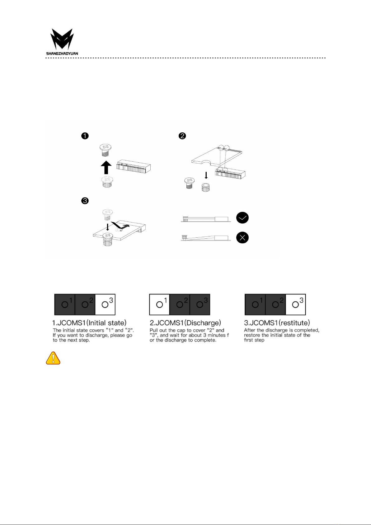
JCMOS1: CMOS Discharge
Wichtig
• Always turn off the computer and unplug the power cord from the power outlet before
discharging.
Any problem, please feel free to contact us.
8
JCOM1: Serial Port Connector
The COM connector can provide one serial port via an optional COM port cable.
ATXPWR1, JATXPWR1: Power Connectors
With the use of the power connector, the power supply can provide enough stable power to
all the components on the motherboard. Before connecting the power connector, make sure
the power supply is turned off and all devices are properly installed.
Wichtig
• It is recommended that a power supply that can withstand high power consumption be
used (at least 500W). If a power supply is used that does not provide the required power,
the result can lead to an unstable or unbootable system.

Any problem, please feel free to contact us.
9
CPU_FAN1, SYS_FAN1: Fan Connectors
CPU_FAN is a interface for CPU radiator. The 4pin fan has PWM intelligent speed regulation
function, which can intelligently control the fan speed based on load and temperature
changes.
SYS_FAN is the system cooling fan interface, which is generally connected to the case fan.
FUSB1~2: USB 2.0 Connectors
The headers conform to USB 2.0 specification. This connector allows you to connect USB 2.0
ports on the front panel.
USB30_1: USB 3.0 Connector
The header conforms to USB 3.0 and USB 2.0 specification. This connector allows you to
connect USB 3.0 ports on the front panel.
Any problem, please feel free to contact us.
10
BIOS Setup
BIOS (Basic Input and Output System) records hardware parameters of the system in the
CMOS on the motherboard. BIOS identifies, configures, tests and connects computer
hardware to the OS immediately after a computer is turned on.
Its major functions include conducting the Power-On Self-Test (POST) during system startup,
saving system parameters and loading the operating system, etc. BIOS includes a BIOS Setup
program that allows the user to modify basic system configuration settings or to activate
certain system features.
When the power is turned off, the battery on the motherboard supplies the necessary
power to the CMOS to keep the configuration values in the CMOS.
Wichtig
• Because BIOS flashing is potentially risky if you do not encounter problems using the
current version of BIOS, it is recommended that you not flash the BIOS. To flash the BIOS, do
it with caution. Inadequate BIOS flashing may result in system malfunction.
BIOS Setup
The default settings offer the optimal performance for system stability in normal conditions.
It is recommended that you not alter the default settings (unless you need to) to prevent
system instability or other unexpected results. Inadequately altering the settings may result
in the system's failure to boot.
Wichtig
• BIOS items are regularly updated for better system performance. The items may be slightly
different from the latest BIOS; therefore, the description is for reference only.
Enter BIOS Setup
Entering BIOS Setup
When the computer starts up, BIOS enters the self-test process. When the self-test is
completed, the following message is displayed: Press DEL key to enter Setup Menu. At this
time, Press <Delete> key to enter the BIOS setup.
If this message disappears before you press <DEL> key, you can turn it off and then turn on
your computer or press <Reset> on the case to restart your computer. You can also press
<Ctrl>+<Alt>+<Delete> at the same time to restart your computer.
It is recommended to repeatedly press the "Del" key immediately after starting the
computer to ensure that the computer can enter BIOS mode.

Any problem, please feel free to contact us.
11
Current Version
Wichtig
• Functions may vary depending on the product you have.
Reset BIOS
When you need to restore the default BIOS settings to resolve certain issues, there are
several ways to reset the BIOS:
∙ Go to BIOS and press F6 to load optimized defaults.
∙ Short the Clear CMOS jumper on the motherboard.
Wichtig
• Be sure the computer is off before clearing CMOS data. Please refer to the Clear CMOS
jumper section for resetting BIOS.


Any problem, please feel free to contact us.
Inhalt
Spezifikationen....................................................................................................... 1
Übersicht der Komponenten.............................................................................2
Installieren CPU & Fan ........................................................................................... 3
Arbeitsspeicher installieren ...................................................................................4
Anschlüsse auf der Rückseite ................................................................................ 4
USB 2.0-Anschluss ............................................................................................5
USB 3.0-Anschluss ............................................................................................5
VGA-Anschluss................................................................................................. 5
HDMI-Anschluss ...............................................................................................5
RJ45 LAN-Anschluss......................................................................................... 5
PS/2-Anschluss .................................................................................................5
Interne Anschlüsse .................................................................................................6
F_PANEL1-Anschluss........................................................................................ 6
SPEAK1-Anschluss ............................................................................................ 6
4 * SATA 2.0-Anschlüsse ...................................................................................6
MSATA-Steckplätze...........................................................................................7
JCMOS1: CMOS-Entladung .............................................................................. 7
JCOM1: Anschluss für serielle Schnittstelle ..................................................... 7
ATXPWR1, JATXPWR1: Stromanschlüsse ......................................................... 8
CPU_FAN1, SYS_FAN1: Lüfteranschlüsse ......................................................... 9
FUSB1~2: USB 2.0-Anschlüsse ......................................................................... 9
USB30_1: USB 3.0-Anschluss ........................................................................... 9
BIOS-Setup.............................................................................................................. 10
BIOS-Setup ............................................................................................................10
Rufen Sie das BIOS-Setup auf .............................................................................. 10
BIOS zurücksetzen ................................................................................................ 11
Any problem, please feel free to contact us.
1
Spezifikationen
BTC B250C
Prozessor
Unterstützt Intel 6th/7th Gen Core i3/i5/i7 (Intel Skylake full series), Xeon E3
1230 V5, Celeron und Pentium Series Prozessoren.
Südbrücke
B250-Chipsatz
RAM
Technologie
Dual-Channel-DDR4
Maximale Kapazität
32 GB (16 GB*2)
Speichersteckplatz
2 * DDR4
E/A hinten
PS/2
2 (Grün: Maus, Lila: Tastatur)
Anzeigeschnittstelle
1 x HDMI, 1 x VGA
USB
2 * USB 2.0, 2 * USB 3.0
Ethernet
1 * Gigabit-LAN
Interner
Anschluss
CFAN
1 * 4 PIN
SFAN
1 * 4 PIN
ATXPWR-Schnittstell
e
24+4+6PIN Steckdose
USB2.0 (vorne)
2
USB3.0 (vorne)
1
MSATA
1
SATA-Schnittstelle
4 * SATA 2.0
JPSON
1
SPRECHEN1
1
JCMOS-Port
1
PCIe
0
Umfeld
Temperaturbereich
Arbeitsumfeld
Speicherumgebung
Temperatur:0~50°C
Feuchtigkeit:5%~95%
Temperatur: -20~70°C
Feuchtigkeit: 5%~95%
Physische
Größe
Größe
175*230 mm

Any problem, please feel free to contact us.
2
Übersicht der Komponenten
Übersicht der KomponentenPaketliste:
BTC B250C Mainboard* 1
SATA-Kabel * 1
Any problem, please feel free to contact us.
3
Installieren CPU & Fan
Bitte installieren Sie die CPU wie unten gezeigt im CPU-Sockel (LGA 1151).
Wichtig
• Stellen Sie sicher, dass das Motherboard die CPU unterstützt.
• Ziehen Sie immer das Netzkabel aus der Steckdose, bevor Sie die CPU installieren oder
entfernen, um Hardwareschäden zu vermeiden.
• Bitte bewahren Sie die CPU-Schutzkappe nach dem Einbau des Prozessors auf.
• Schalten Sie den Computer nicht ein, wenn der CPU-Kühler nicht installiert ist, da es sonst
zu einer Überhitzung und Beschädigung der CPU kommen kann.
• Stellen Sie sicher, dass der CPU-Kühlkörper eine dichte Verbindung mit der CPU gebildet
hat, bevor Sie Ihr System booten.
• Tragen Sie eine gleichmäßige Schicht Wärmeleitpaste (oder Wärmeleitband) zwischen der
CPU und dem Kühlkörper auf, um die Wärmeableitung zu verbessern.
• Wenn die CPU nicht installiert ist, schützen Sie immer die Stifte des CPU-Sockels, indem Sie
den Sockel mit einer Plastikkappe abdecken.
• Lokalisieren Sie Pin 1 des CPU-Sockels und der CPU. Sobald die CPU in ihrem Sockel
positioniert ist, legen Sie einen Finger auf die Mitte der CPU, senken Sie den
Verriegelungshebel und verriegeln Sie ihn in der vollständig verriegelten Position.
• Setzen Sie die CPU nicht mit Gewalt in den CPU-Sockel ein, bevor der Verriegelungshebel
des CPU-Sockels angehoben ist, da sonst die CPU und der CPU-Sockel beschädigt werden
können.
• Verbinden Sie den 4-Pin-Lüfterstromanschluss des CPU-Kühlkörpers mit dem
4-Pin-CPU-Lüfteranschluss auf dem Motherboard.

Any problem, please feel free to contact us.
4
Arbeitsspeicher installieren
Das Motherboard bietet 2 DDR4-DIMM-Steckplätze mit einer maximalen Kapazität von 32
GB.
1. Drehen Sie die Riegel auf beiden Seiten des Speichersteckplatzes nach außen.
2. Setzen Sie den Speicher in den Steckplatz ein, indem Sie ihn an der Kerbe im Steckplatz
ausrichten.
3. Klappen Sie die Riegel auf beiden Seiten des Steckplatzes um, um den Speicher zu
verriegeln.
Wichtig
• Stellen Sie sicher, dass das Motherboard den Speicher unterstützt. Es wird empfohlen,
Speicher gleicher Kapazität, Marke, Geschwindigkeit und Chips zu verwenden.
• Schalten Sie den Computer immer aus und ziehen Sie das Netzkabel aus der Steckdose,
bevor Sie den Speicher installieren, um Schäden an der Hardware zu vermeiden.
• Speichermodule haben ein narrensicheres Design. Ein Speichermodul kann nur in einer
Richtung installiert werden. Wenn Sie den Speicher nicht einsetzen können, ändern Sie die
Richtung.
• Die Stabilität und Kompatibilität des installierten Speichermoduls hängt beim Übertakten
von der installierten CPU und den Geräten ab.
• Dieses Motherboard bietet zwei Speichersteckplätze und unterstützt die
Dual-Channel-Technologie. Der Dual-Channel-Modus kann nicht aktiviert werden, wenn nur
ein Speichermodul installiert ist.
Anschlüsse auf der Rückseite

Any problem, please feel free to contact us.
5
USB 2.0-Anschluss
Der USB-Anschluss unterstützt die USB 2.0-Spezifikation. Verwenden Sie diesen Anschluss
für USB-Geräte.
USB 3.0-Anschluss
USB 3.0 unterstützt die USB 3.0-Spezifikation und ist mit der USB 2.0-Spezifikation
kompatibel. Verwenden Sie diesen Anschluss für USB-Geräte.
VGA-Anschluss
VGA (Video Graphics Array) unterstützt analoge Videosignalübertragung, hohe Auflösung,
schnelle Anzeigerate und satte Farben.
HDMI-Anschluss
Der HDMI-Anschluss unterstützt 4K und 1080px. Sie können diesen Anschluss verwenden,
um Ihren HDMI-unterstützten Monitor anzuschließen.
RJ45 LAN-Anschluss
Der Gigabit-Ethernet-LAN-Anschluss bietet eine Internetverbindung mit einer Datenrate von
bis zu 1000 Mbit/s.
Im Folgenden werden die Zustände der LAN-Port-LEDs beschrieben.
PS/2-Anschluss
Der PS/2-Anschluss der Maus ist grün und der PS/2-Anschluss der Tastatur ist blau.
Table of contents
Languages:
Other Shangzhadyuan Motherboard manuals


