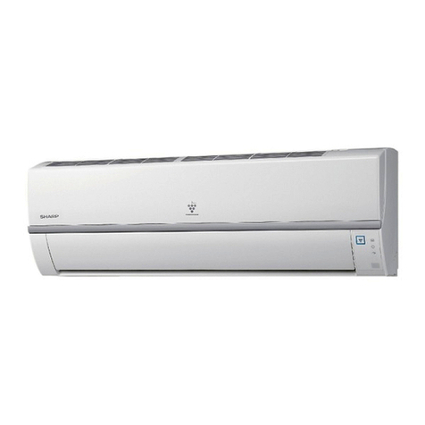
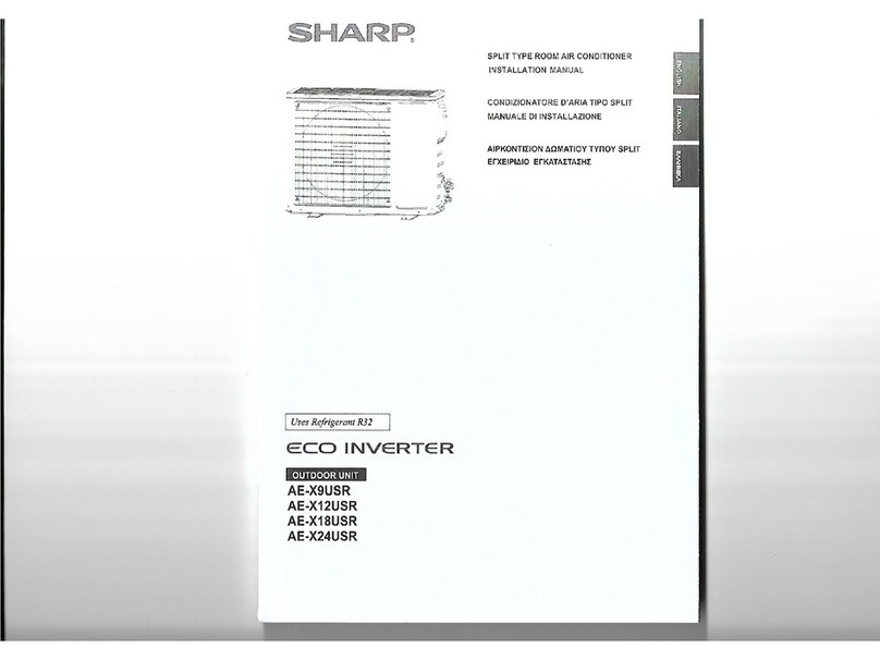
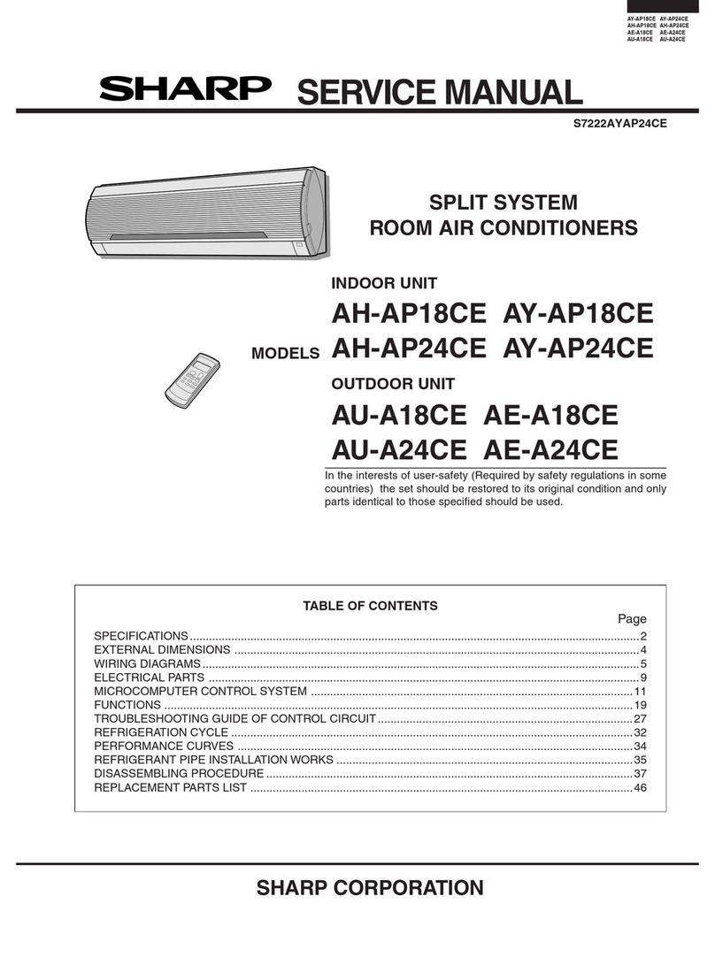
Sharp AE-XM30GR User manual

SERVICE MANUAL
AEXM30GR
S9619AEXM30GR
MULITI SPLIT TYPE
ROOM AIR CONDITIONERS
OUTDOOR UNIT
AE-XM30GR
MODEL
Parts marked with " " are important for maintaining the safety of the set. Be sure to replace these parts with specified ones for maintaining the
safety and performance of the set.
This document has been published to be used for
after sales service only.
The contents are subject to change without notice.
CHAPTER 1. SPECIFICATION
[1] SPECIFICATION ...........................................1-1
[2] EXTERNAL DIMENSION ..............................1-2
[3] CAPACITY TABLE.........................................1-2
[4] ELECTRICAL PARTS....................................1-4
[5] WIRING DIAGRAMS .....................................1-4
CHAPTER 2. EXPLANATION OF CIRCUIT AND OP-
ERATION
[1] BLOCK DIAGARM.........................................2-1
[2] FUNCTIONS..................................................2-2
CHAPTER 3. FUNCTION AND OPERATION OF PRO-
TECTIVE PROCEDURES
[1] PROTECTIVE FUNCTIONS AND OPERA-
TIONS............................................................3-1
[2] TROUBLESHOOTING GUIDE ......................3-2
CHAPTER 4. REFRIGERATION CYCLE
[1] REFRIGERATION SYCLE ............................. 4-1
[2] REFRIGERANT PIPE INSTALLATION
WORKS.......................................................... 4-3
CHAPTER 5. DISASSEMBLING PROCEDURE
[1] OUTDOOR UNIT ........................................... 5-1
Parts Guide
TopPage
CONTENTS
In the interests of user-safety (Required by safety regulations in some countries)
the set should be restored to its original condition and only parts identical to those
specified should be used.

AE-XM30GR
1 – 1
AE-XM30GR Service Manual
CHAPTER 1. SPECIFICATION
[1] SPECIFICATION
NOTE: The condition of star “✩“marked item are ‘ISO5151’: *: Representative connection
MODEL INDOOR UNIT OUTDOOR UNIT
ITEMS AY-XPM7FR/9FR/12FR AE-XM30GR
Cooling capacity kW
4-INDOOR OPERTION 9K&7K&7K&7K 8.4(4.3–9.0)*
Heating capacity kW
4-INDOOR OPERTION 9K&7K&7K&7K 9.0(4.4–10.6)*
Moisture removal (at cooling)✩Liters/h 1.0&0.8X3*
Electrical data
Phase Single
Rated frequency Hz 50
Rated voltage V 230V
Rated current Cool A 13.7(4.9– 16.0)*
Heat A 11.0 (4.3 – 14.0)*
Rated input ✩
(Min. - Max.)
Cool W 2990 (1070– 3490)*
Heat W 2400 (940 – 3060)*
Power factor ✩Cool % 95
Heat % 95
Compressor Type Hermetically sealed DC twin rotary
Model DA220A2F-20L
Oil charge Ester oil VG74
Refrigerant system Evaporator Silt Fin and Grooved tube type
Condenser Corrugate Fin and Grooved tube type
Control Expansion valve
Name of refrigerant R410A
Refrigerant volume 2400g
Noise level (at cooling) dB(A) High/Med/Low
7FR: 37/34/28 57
9FR: 39/36/28
12FR: 40/37/29
Fan system
Drive Direct drive
Air flow quantity
(at cooling)
.
m3/min.
High/Med/Low
7FR: 8.0/7.4/5.4 52
9FR: 8.6/7.9/5.6
12FR: 9.8/8.6/8.6
Fan Cross flow fan Propeller fan
Connections
Refrigerant coupling Flare type
Refrigerant tube size Gas, Liquid 1/2”, 1/4”(18class only),3/8”,1/4”
Maximum length (per unit) m 20
Maximum length (total) m 50
Maximum charge-less length m 50
Maximum height difference m 10
Drain joint mm O.D18
Others
Safety device Compressor: Thermistor
Fan motors: Thermal fuse (indoor unit).
Thermal protector (Out door unit)
Fuse, Micro computer control
Anti-mold polypropylene net of injection type
(Washable)
Net dimensions Width mm 790 940
Height mm 278 800
Depth mm 198 357
Net weight kg 10 70

AE-XM30GR
1 – 2
[2] EXTERNAL DIMENSION
[3] CAPACITY TABLE
Recommended Combination
Outdoor Units Indoor Units
AY-XPM7/9/12FR,GS-XPM9/12/18FGR,GS-XPM7/9/12FR
AE-XM30FR
18 12 7 -
18 9 9 -
18 9 7 -
18 7 7 -
12 12 7 7
12 9 9 7
99 99
12 9 7 7
99 97
12 7 7 7
99 77
97 77
77 77
32037
890
361
383
800
590
¿4.5
150
51.3
16
75
150
52 52 52 52389
284
210151
26
940 50
26

AE-XM30GR
1 – 3
COOLING CAPACITY TABLE
HEATING CAPACITY TABLE
Operating
Status
Combination of Indoor
Units Cooling Capacity (kW) Running Current (A) Power Consumption
(W)
A B C D A B C D RATING (Min.-Max.) RATING (Min.-Max.) RATING (Min.-Max.)
4-Room
12 12 07 07 2.65 2.65 1.55 1.55 8.4 (4.3-9.0) 13.7 (4.9-16.0) 2990 (1070-3490)
12 09 09 07 2.73 2.04 2.04 1.59 8.4 (4.3-9.0) 13.7 (4.9-16.0) 2990 (1070-3490)
09 09 09 09 2.10 2.10 2.10 2.10 8.4 (4.3-9.0) 13.7 (4.9-16.0) 2990 (1070-3490)
12 09 07 07 2.88 2.16 1.68 1.68 8.4 (4.3-9.0) 13.7 (4.9-16.0) 2990 (1070-3490)
09 09 09 07 2.22 2.22 2.22 1.74 8.4 (4.3-9.0) 13.7 (4.9-16.0) 2990 (1070-3490)
12 07 07 07 3.06 1.78 1.78 1.78 8.4 (4.3-9.0) 13.7 (4.9-16.0) 2990 (1070-3490)
09 09 07 07 2.36 2.36 1.84 1.84 8.4 (4.3-9.0) 13.7 (4.9-16.0) 2990 (1070-3490)
09 07 07 07 2.52 1.96 1.96 1.96 8.4 (4.3-9.0) 13.7 (4.9-16.0) 2990 (1070-3490)
07 07 07 07 2.00 2.00 2.00 2.00 8.0 (4.3-9.0) 12.7 (4.9-16.0) 2780(1070-3490)
3-Room
18 12 07 - 4.04 2.69 1.57 - 8.3 (4.3-8.9) 13.7 (4.9-16.0) 2990 (1070-3490)
18 09 09 - 4.15 2.08 2.08 - 8.3 (4.3-8.9) 13.7 (4.9-16.0) 2990 (1070-3490)
18 09 07 - 4.39 2.20 1.71 - 8.3 (4.3-8.9) 13.7 (4.9-6.0) 2990 (1070-3490)
18 07 07 - 4.67 1.82 1.8 - 8.3 (4.3-8.9) 13.7 (4.9-16.0) 2990 (1070-3490)
12 12 07 OFF 3.0 3.0 1.8 OFF 7.8 (3.6-8.4) 13.7 (4.0-15.1) 2990 (880-3300)
12 09 09 OFF 3.2 2.3 2.3 OFF 7.8 (3.6-8.4) 13.7 (4.0-15.1) 2990 (880-3300)
09 09 09 OFF 2.5 2.5 2.5 OFF 7.4(3.6-8.4) 12.1 (4.0-15.1) 2650 (880-3300)
12 09 07 OFF 3.3 2.4 1.9 OFF 7.6 (3.6-8.4) 12.8 (4.0-5.1) 2800 (880-3300)
12 07 07 OFF 3.4 1.9 1.9 OFF 7.2 (3.6-8.4) 11.7 (4.0-15.1) 2550 (880-3300)
09 09 07 OFF 2.5 2.5 2.0 OFF 7.0 (3.6-8.4) 11.0 (4.0-15.1) 2400 (880-3300)
09 07 07 OFF 2.6 2.0 2.0 OFF 6.6 (3.6-8.2) 9.9 (4.0-14.6) 2160 (880-3200)
07 07 07 OFF 2.0 2.0 2.0 OFF 6.0(3.6-7.8) 8.8 (4.0-14.2) 1920 (880-3100)
2-Room
18 12 OFF - 4.56 3.04 OFF - 7.6 (3.6-8.0j 13.7 (4.0-15.6) 2990 (880-3400)
18 9 OFF - 4.80 2.40 OFF - 7.2 (3.6-8.0j 11.9 (4.0-15.6) 2600 (880-3400)
18 7 OFF - 4.90 1.90 OFF - 6.8 (3.6-8.0j 10.8 (4.0-15.6) 2350 (880-3400)
12 12 OFF OFF 3.1 3.1 OFF OFF 6.2 (2.6-7.5j 10.3 (3.2-16.9) 2250 (700-3700)
12 09 OFF OFF 3.2 2.4 OFF OFF 5.6 (2.6-7.1j 8.9 (3.2-14.6) 1950 (700-3200)
12 07 OFF OFF 3.3 2.0 OFF OFF 5.3 (2.6-6.8) 7.9 (3.2-12.7) 1720(700-2770)
09 09 OFF OFF 2.5 2.5 OFF OFF 5.0 (2.6-6.3) 7.5 (3.2-11.9) 1630 (700-2600)
09 07 OFF OFF 2.6 2.0 OFF OFF 4.6 (2.6-5.9) 6.4 (3.2-10.3) 1400 (700-2250)
07 07 OFF OFF 2.0 2.0 OFF OFF 4.0 (2.6-5.3) 5.5 (3.2-8.7) 1200 (700-1900)
1-Room
18 OFF OFF OFF 5.0 OFF OFF - 5.0 (2.6-5.7) 7.3 (3.2-11.0) 1600 (700-2400)
12 OFF OFF OFF 3.4 OFF OFF OFF 3.4 (1.8-4.0) 5.0 (2.9-6.6) 1100 (630-450)
09 OFF OFF OFF 2.6 OFF OFF OFF 2.6 (1.8-3.3) 3.6 (2.9-4.9) 790 (630-1080)
07 OFF OFF OFF 2.0 OFF OFF OFF 2.0 (1.8-2.7) 3.4 (2.9-3.9) 750 (630-850)
Operat-
ing Status
Combination of Indoor
Units Heating Capacity (kW) Running Current (A) Power Consumption
(W)
A B C D A B C D RATING (Min.-Max.) RATING (Min.-Max.) RATING (Min.-Max.)
4-Room
12 12 07 07 2.84 2.84 1.66 1.66 9.0 (4.4-10.6) 11.0 (4.3-14.0) 2400 (940-3060)
12 09 09 07 2.92 2.19 2.19 1.70 9.0 (4.4-10.6) 11.0 (4.3-14.0) 2400 (940-3060)
09 09 09 09 2.25 2.25 2.25 2.25 9.0 (4.4-10.6) 11.0 (4.3-14.0) 2400 (940-3060)
12 09 07 07 3.09 2.31 1.80 1.80 9.0 (4.4-10.6) 11.0 (4.3-14.0) 2400 (940-3060)
09 09 09 07 2.38 2.38 2.38 1.85 9.0 (4.4-10.6) 11.0 (4.3-14.0) 2400 (940-3060)
12 07 07 07 3.27 1.91 1.91 1.91 9.0 (4.4-10.6) 11.0 (4.3-14.0) 2400 (940-3060)
09 09 07 07 2.53 2.53 1.97 1.97 9.0 (4.4-10.6) 11.0 (4.3-14.0) 2400 (940-3060)
09 07 07 07 2.70 2.10 2.10 2.10 9.0 (4.4-10.6) 11.0 (4.3-14.0) 2400 (940-3060)
07 07 07 07 2.13 2.13 2.13 2.13 8.5 (4.4-9.8) 10.2 (4.3-13.0) 2230(940-2850)
3-Room
18 12 07 - 4.33 2.89 1.68 - 8.9 (4.4-10.5) 11.0 (4.3-14.0) 2400 (940-3060)
18 09 09 - 4.45 2.33 2.23 - 8.9 (4.4-10.5) 11.0 (4.3-14.0) 2400 (940-3060)
18 09 07 - 4.71 2.36 1.83 - 8.9 (4.4-10.5) 11.0 (4.3-14.0) 2400 (940-3060)
18 07 07 - 5.01 1.95 1.95 - 8.9 (4.4-10.5) 11.0 (4.3-14.0) 2400 (940-3060)
12 12 07 OFF 3.4 3.4 2.0 OFF 8.8 (3.6-10.0) 12.1(3.8-14.4) 2650(830-3150)
12 09 09 OFF 3.6 2.6 2.6 OFF 8.8 (3.6-10.0) 12.1(3.8-14.4) 2650(830-3150)
09 09 09 OFF 2.9 2.9 2.9 OFF 8.8 (3.6`10.0) 12.1(3.8-14.4) 2650(830-3150)
12 09 07 OFF 3.8 2.8 2.2 OFF 8.8 (3.6-10.0) 12.1(3.8-14.4) 2650(830-3150)
12 07 07 OFF 3.9 2.3 2.3 OFF 8.5 (3.6-10.0) 11.4 (3.8-14.4) 2500 (830-3150)
09 09 07 OFF 3.0 3.0 2.2 OFF 8.2 (3.6-10.0) 11.0 (3.8-14.4) 2400 (830-3150)
09 07 07 OFF 3.0 2.4 2.4 OFF 7.8 (3.6-9.4) 9.8 (3.8-13.7) 2150 (830-2990)
07 07 07 OFF 2.4 2.4 2.4 OFF 7.1(3.6-8.8) 8.6 (3.8-12.2) 1870 (830-2660)

AE-XM30GR
1 – 4
[4] ELECTRICAL PARTS
[5] WIRING DIAGRAMS
2-Room
18 12 OFF - 4.86 3.24 OFF - 8.1 (3.6-9.0j 11.2 (3.8-15.1) 2450 (830-3300)
18 9 OFF - 5.40 2.70 OFF - 8.1 (3.6-9.0j 11.2 (3.8-15.1) 2450 (830-3300)
18 7 OFF - 5.54 2.16 OFF - 7.7 (3.6-9.0j 10.1 (3.8-15.1) 2200 (830-3300)
12 12 OFF OFF 3.8 3.8 OFF OFF 7.6 (2.6-8.0j 11.9 (3.3-13.3) 2600 (730-2900)
12 09 OFF OFF 3.8 2.9 OFF OFF 6.7 (2.6-8.0j 10.3 (3.3-13.3) 2250 (730-2900)
12 07 OFF OFF 3.9 2.2 OFF OFF 6.1 (2.6-8.0) 8.7 (3.3-13.3) 1900(730-2900)
09 09 OFF OFF 2.9 2.9 OFF OFF 5.8 (2.6-8.0) 8.5 (3.3-13.3) 1850 (730-2900)
09 07 OFF OFF 3.0 2.3 OFF OFF 5.3(2.6-7.3) 6.9 (3.3-11.0) 1510 (730-2400)
07 07 OFF OFF 2.4 2.4 OFF OFF 4.8(2.6-6.4) 6.2 (3.3-9.2) 1350 (730-2000)
1-Room
18 OFF OFF OFF 5.0 OFF OFF - 6.2 (2.6-7.4) 10.1 (3.3-13.7) 2200 (730-3000)
12 OFF OFF OFF 3.8 OFF OFF OFF 3.8 (1.8-5.2) 7.3(2.9-10.1) 1600 (640-2200)
09 OFF OFF OFF 2.9 OFF OFF OFF 2.9 (1.8-4.0) 5.2 (2.9-8.0) 1130 (640-1750)
07 OFF OFF OFF 2.4 OFF OFF OFF 2.4 (1.8-3.4) 4.0 (2.9-6.2) 870 (640-1350)
Compressor DA220A2F-20L Hermetically sealed DC twin rotary
Outdoor fan motor MLB051 230V, 50Hz
Outdoor fan motor capacitor — 500V, 3F
Fuse 1,2 — QFS-GA065JBZZ(20A,250V)
Fuse 6 — QFS-GA064JBZZ(1A,250V)
Fuse 3,4 — QFS-GA062JBZZ(3.15A,250V)
Operat-
ing Status
Combination of Indoor
Units Heating Capacity (kW) Running Current (A) Power Consumption
(W)
A B C D A B C D RATING (Min.-Max.) RATING (Min.-Max.) RATING (Min.-Max.)
CC298

AE-XM30GR
1 – 5
CONTROL P.W.B and DISPLAY P.W.B
from 4 WAY VALVE
from CONTROL BOX
from DIODE BRIDGE
DB1 "~" from HEAT-SINK
THERMISTOR
from THERMISTOR
(SUCTION)
from THERMISTOR
from DC FAN MOTOR
COMP. TENP.
HEAT EXCHANGER TEMP.
OUT DOOR TEMP.
SUCTION TEMP.
to IPM PWB CN102
from IPM PWB CN114 from IPM PWB
"U", "V", "W"
from EXPANSION VALVE D
from EXPANSION VALVE C
to IPM PWB CN101
to ACTIVE FILTER MODULE
from EXPANSION VALVE B
from EXPANSION VALVE A from TERMINAL BOARD
"N" and "2"
from TERMINAL BOARD "N"
from TERMINAL BOARD "1"

AE-XM30GR
1 – 6
IPM P.W.B.
from CONTROL PWB BCN1
from CONTROL PWB
BCN2
from CONTROL PWB
CN14
from ELECTROLTIC CAPACITOR C10 "+"
from ELECTROLTIC
CAPACITOR C10 "-"
from COMPRESSOR CORD
W "ORANGE"
V "WHITE"
U "RED"
from COMPRESSOR CORD

AE-XM30GR
1 – 7
(CONTROL PWB)
TU2
FC7
FC3
FC8
GREEN/YELLOW
BLUE
PURPLE
RED
ORANGE
BROWN BROWN BROWN
BROWN
2
1
FC2
FC4
FC6
FC5
YELLOW
YELLOW
YELLOW
WHITE
WHITE
Io
P
-
+
L1 L2
SACT32420C
ACT (PFC)
AF1
1500μF
420V
C10
1500μF
420V
C9
+
-
-
BLUE BLUE BLUE
BLACK
2
1
2
1
2
1
1
: 130K 1/4W
R113, 114,
116, 192
R192
R116
R112
R113
T7
3
1
1.0K F
T1
GND
GND
C36
10 10
BCN1
CN101CN101
25
24
23
W
V
U
TV
TW
RED
ORANGE
FC1
C
WHITE
1/2W 180K F
R58, R60, R62 :
1/2W 196K F
R57, R59, R61 :
1/2W 196K F
R55, 56 :
10K
390
C52
e
PC8 :
NR3
T6
BROWN
D1 1.0K F
R11
FUSE4
3.15A
250V
PTC1
C45
C53
(T2)
T8
C3
275V 1μF
C16, C18 :
250V
10000pF
C12, C14 :
C11, C13 :
4700pF
250V
C15, C17 :
C79
C79, C93 :
C93
3
4
1
2
1/4W 1/2W
1/2W
1/2W
1/2W
PC1
PC81716
150K
150K
150K
150K
47K
5.6K
275V 2.2μF
C8, 20 :
C20
C8
CT1
L5
PC817X3
PC81716
PC10, 11 :
9
8
7
6
5
4
3
2
11
2
3
4
5
6
7
8
9
50V
0.1μF
U
Z
Y
X
W
V
9
8
7
6
5
4
3
2
1U
Z
Y
X
W
VV
W
X
Y
Z
U
10K
R80
CN11
(DISPLAY PWB)
413
52
8
Motor
Fan
CN3A
CN16
R62
R61
R60R59
R58R57
R56
R55
R54
R53
R52
14.7K F
14.7K F
14.7K F
GREEN/YELLOW
(TERMINAL BOARD)
N
BLUE
7.5K F
CN14
1/4W
1/4W
R47
100
1/4W
100
1/4W
1/4W
1/4W
1/4W
CN114
CN13
50V
3
IC4
100
1W
FUSE2
250V
20A
N
16
17
C121
0.33μF
630V
N
(TERMINAL BOARD)
GREEN/YELLOW
BLUE
GREEN/YELLOW
BLUE
(TERMINAL BOARD) (TERMINAL BOARD)
N
N
(TERMINAL BOARD)
GREEN/YELLOW
BLUE BLUE
BROWN
GRAY
BLACK
MRY1
275V
0.033μF
C4 R15
RY3
C26 :
C26
C23
C27
C33
C42
C41
C40
C39
PC817X3
PC5, PC6, PC7 :
R51
R50
R49
R48
R44
R45
R46
R12
R10
1
4
-
+
3.3K
3.3K
3.3K
100
100
50V
0.1μF
0.1μF
330pF50V
330pF50V
330pF50V
TN
TP
IPM PWB
20A 250V
QM101 (IPM)
N
26
22
P
T4
NR1 SA1
275V 1μF
C2
L4
L3
R1
1/4W
510K
R2
1/4W
510K
C1
-
+
C11
C13 C14
C12
C15 C16
C17 C18
BROWN ORANGE
DB1
AC1
AC2
+
C19
10V 220μF
6.49K F
275V 1μF
T5
IC5
KIA339P
12 -
PC5
PC6
PC7
8
9
-
+
6
7
-
+
1
14
+
11
10
13
4
4
4
2
1
1
2
2
1
3
3
3
CN4
Valve
4-WAY
MR2920
32
7
5
6
PC817X3
1.8K F
RY3
3.15A
250V
NR2
FUSE3
BLUE
FUSE1
4MHz
OSC1
C98
50V
0.1μ
D39
2.2K
2.2K
2.2K
2.2K
10K
C84
D38
L1
PC942
PC942
PC942
PC942
PC942
PC942
(SUCTION D)
(SUCTION C)
(SUCTION B)
(SUCTION A)
10μF50v
writer
flash
CND
33
R110, R111, 190, 191 :
R191 R111
R190 R110
270
270
C89
C88
C87
C86
C95
C92
C91
C90
C94
C59
C60
C61
C58
C57
C56
C55
R161
R162
R163
R164
R165
R166
R167
R159
R64
R65
R66
R67
R71
R70
R69
R68
0.01μ
16V
C68
CN8A
CN8C
(outdoor)
(haet exchange)
(compressor)
TH1
(suction )
TH4
TH3
TH2
TH9
TH6
TH7
TH8
4.7K
1K
R154
D37
D36
D35
D34
KRC245M
KRC245M
KRC245M
KRC245M
4.7K
10K
15KF
1.8KF
2.7KF
4.7K
R157 10K
R141 10K
GND
S24CS02
R153 1K
R152
GND
IC6
8
7
5
6
1
2
4
3
CNE
4
3
1
2
(EEPROM)
5V
R151
KRC106M
Q7
GND
GND
GND
1K
R155
JP5
JP4
GND
GND
GND
GND
1.5k
1.5k
JP3
330pF
D33
D32
GND
4
4
0.01μ
C63
50V
250V
GND
15V
5.6k
R72
1.0K
2W
R117
C81
4700P C82
50V
0.1μ
R76
R75
2
Q13
KRA106M
3
2
1
C80
0.1μ
R171
50V
10k
R74
PC9
PC8
3
1
5V
C64
250V
FUSE5
2A
6.8K F
R31
GND
GND
GND
GND
GND
50V
C78
1000p
C51
50V
0.01μF
GND
S
R
c
b
a
d
R81
R82
R83
R84
R85
R86
R87
1/4W
R82 - R87 :
9
8
7
6
5
4
3
2
1
(CN)
4
3
2
1
5W 0.018
(UNIT D)
(UNIT C)
(UNIT B)
JPF
1/4W
1/4W
Q9
Q10
Q12
Q11
1/4W
1/4W
1/4W
1/4W
1/4W
1/4W
R95
R94
R93
R92
R91
R90
R88 R89 R96
2SA1020Y
2SA1020Y
R175 - R177
R177
R176
R175
R107
R106
0.01μF
50V
d
c
b
a
R156
C86 - C92, C95 : 0.01μ50V
C55 - 61, C94 : 10μ16V
R71 :
R159, R161 - R167 : 10K
C83
R103
R104
R105
R102
PC19
PC18
R118 R119
R77
3.3k
D14
P
P
T
WINTER COOL
1/2W 1/2W 270KF
270KF
4700pF 250V
100μF
25V
IC9
MM1431
0.1μF
50V
10K
R172
monitor
GND
5V
10K
R173
m
R174 10K
f
Q
T
S
R
B
S
Q
GND
0.1μ
50V
C46 IC2
PST993D
R
5V C47
1μ 50V
5V
R9
R3
R4
C21
50V
0.01μF
R169
R5
R168
D2
D30
m
GND
C43
10V
100μ
0.1μ
50V
C44 5V
C48
C49
C50
:10K
2.7k
3.3k
R79
GND
GND
R64 - 6.8kF
(thermistor)
6
5
4
3
2
1
7
8
CN12A
CN12B
IC1
6463626160595857565554535250494847464544434241 51
C
P23
VCC
P22
P21
P20
P17
P16
P15
P14
P13
P12
P11
P10
P07
P06
P05
P04
P03
P02
P01
P00
VCC
VSS
1234567891011121314151617181920212222324
AVR
AVSS
AVCC
P67
P66
P65
P64
P63
P62
P61
P60
P51
P50
P47
P46
P45
P44
P43
RST
P42
P41
VSS
X0
X1
25
26
27
28
29
30
31
32
33
34
35
36
37
38
39
40
MD0
MD1
MD2
P40
P37
P36
P35
P34
P33
P32
P31
P30
P27
P26
P25
P24
80
79
78
77
76
75
74
73
72
71
70
69
68
67
66
65
P70
P71
P72
P73
P74
P75
P76
P77
P80
P81
P82
P83
P84
P85
P86
P87
(U)
(X)
(V)
(Y)
(W)
(Z)
(W)
(V)
(U)
(B)
(W)
(Y)
(O)
WO
Y
CN12C
1/4W 10K
1K
1K
1K
1K
JP1
10K
10K
10K
R97
R98
R99
1/4W
1/4W
1/4W
3
2
1
Y
W
D29
D28
D27
D26
W
Y
O
BL
R
1
2
3
4
55
GR 6
(valve C)
2SA1020Y
2SA1020Y
GR 6
Y
W
O
BL
R5
4
3
2
1
D22
D23
D24
D25
(valve B)
(valve A)
D21
D20
D19
D18
1
2
3
4
5
6
W
Y
O
BL
R
GR
+
-
5
1
D101
VP
VVFS
VVFB
VUFS
VPI
VUFB
VPI
UP
1
2
8
PC101
76
1
PC102
276
8
18
5
5
0.1μF
1000pF
1000pF C123
C124
0.1μF
C113
C114
C115C115 C114 C113
0.1μF
C124 C123
1000pF 1000pF
0.1μF
5
5
8
1
8
6
7
2PC102
1
6
7
PC101
8
2
1
UP
VPI
VUFB
VPI
VUFS
VVFB
VVFS
VP
D101
1
5
-
+
1/2W
8
7
6
4
3
2
-
+
+
-
C107
C111
D104
D105
0.1μF
C106
0.1μF
C110
0.1μF
C101
100μF
C102
100μF 25V
25V
C109
0.1μF
+
-
C105
100μF
25V25V
100μF
C105
-
+
0.1μF
C109
25V 25V
100μF
C102 100μF
C101
0.1μF
C110
0.1μF
C106
0.1μF
D105
D104
C111
C107
-
+
+
-
2
3
4
6
7
8
C129
IC3
RY3
KID65004AP
MRY1
Q1
Q2
Q3
Q4
B
O
Y
W
19
21
20
VPC
FO
18
32
1
4
PC107
R115
R109
0.1μF
C122
IPM
VNC
VNI
UN
VN
WN
VWFS
2PC104
76
1
2PC105 6
7
18
6
7
2PC106 5
5
8
5
0.1μF 0.1μF
1000pF
R114
47K
1000pF
1000pF
1000pF C126
C127
C128
PC81716
6.8k
47K
0.1μF
C118 C117 C116C116
C117
C118
0.1μF
47K
6.8k
PC81716
C128 C127 C126
1000pF 1000pF 1000pF
47K
R114
1000pF
0.1μF
0.1μF
5
8
5
5
PC106
276
8
1
76
PC105
2
1
6
7
PC104
2
VWFS
WN
VN
UN
VNI
VNC
IPM
C122
0.1μF
R109
R115
PC107
41
2
3
18
FO
VPC
20
21
19
5V
9
WP VWFB
VPI
PC103
276
18
5
0.1μF
C125C125
0.1μF
5
8
1
6
7
2PC103 VPI
VWFB
WP
9
2
11
2
C103
25V
100μF
10
13
14
15
11
12
+
-
-
+
C108
D106
0.1μF
0.1μF
D103
C112
0.1μF
IPM PWB
CN102
25V
330μF
C104
e
Z100
HZ24 - 2HZ24 - 2
Z100
e
C104
330μF
25V
CN102
IPM PWB
0.1μF
C112
D103
0.1μF
0.1μF
D106
C108
+
-
-
+
12
11
15
14
13
10
100μF
25V
C103
50V
1000pF
1000pF
50V
1000pF
50V
CN12D
(valve D)
6
GR
55
4
R
BL
O
13V
R132
2.7k
GND
GND
2.7k
R125
1000P
50V
4.7K
56K
UNIT D
LED4
88 2.2k
BCN11
7
6
5
4
3
2
1
7
6
5
4
3
2
1
10k
10k
WIRE CHECK SW
PUMP DOWN SW
2.2k
2.2k
2.2k
10k
10k
10k
UNIT A
UNIT B
UNIT C
5V
C67
50V 50V
1000p 1000p
C66
R142 R143
R144
R145
10k
R146
R147
R148
R149
R150
JP2
SW1
SW2
LED1
LED2
LED3
2
1
1
1
23
4
23
4
47μF
R78
6.8k
-
+
10V
3
1
2
4
3
1
2
3
4
3.3K
Pc853H
PC817X3
2W
1.0K
2W
1.0K
1
2
1
7
6
5
4
3
8
5V
Pc853H 56K
32
1.0K
R120 R121 R122 R124
0.1μ
C62
50V
PC10
PC11
630V
C65
0.1μ
R73
5.6k
N
1
D
C
B
A
3
5
7
9
(terminal board)
PC12
PC13
PC14
PC15
4700P
C69
PC817X3
PC817X3
PC817X3
2.7k
Pc853H
Pc853H
50V
50V
50V
3.3K
3.3K
3.3K
56K
56K
4.7K
4.7K
4.7K
250V
250V
4700P
C70
41
1000P
3
4
1
2
1
2
14
3
1000P
1
2
3
4
4
32
1
1000P
3
4
1
2
11
C71
4700P
250V
1.0K 1.0K
2W
2W 2W
1.0K
2W
1.0K 1.0K
2W 1.0K
2W
0.1μ
0.1μ
2W 1.0K
2W
0.1μ
1.0K
2W
R126
R127 R128 R129
R123
R130
R131
R133
R134 R135 R136
R137
R138
R139
R140
C77
C76
C75
C74
C73
C72
D15
D16
D17
5V
PC16
PC17
50V
50V
50V
CN6 BLACK
6
124
(UNIT A)
D31
C32
R20, 21, 23 :
R17, 18, 19 :
1/4W
5W
IC5
HZ15 - 1
05NU42
BCN13
1/4W
1/4W
50V
4
52
3
12
KIA339P
3
1/4W
100μF
220μF
10K
10K
50V
820μF
100pF
50V
FUSE6
6V
1.5K
R42
1.5K
R43
R100, R101 :
R100
0.022μF
50V
C120
ZD101
C119
1000pF
R108
50V
5V
1.5K
R41
BCN2
TH5
CN8B
IC10
C28
IC8
13V
27K
ZD3
4700pF
50V
R28
(POWER SUPPLY)
16V
10μ 6.8kF
C54 R63
R16
C22
D3
D5
C24
C25
R19
R18
R17 D4
C31 C30
C29
D9
D7
D6
R20
R21
R22
R23 560
R24
R27
R26R25
R29
R39
R38
C37
R37
R36
C36
C35
C34
R30
R35
R34
R33
R32
R40
1K
50V
0.01μF
25V
100μF
25V
100μF
25V
2.2K 18K
2KV
1
25V
35V
KIA7815API
-
+
+
-
0.01μF
50V
0.1μF
50V
0.1μF
34.8K F
15.8K F
5V
1
(HEATSINK)
250V
1A
24
13
24
13
4321
4321
R101
18V
1.5K
390
10K
50V
0.01μF
+
-
PC817X3
3
1
2
PC3 PC817X3
3.3K
4
4
3
2
1
1M
PC4
18V
6
5
4
3
2
1
560 F
6
5
4
3
2
1
7805
5V
0.1μF
KIA7805API
D8
2
1
15V
7815
18V
TR1
+
-
-
+
+
-
1
4
32
50V
0.1μF
PC2
51K
33
7
6
12
11
12
13
16
17
4
3
2
50V
0.01μ
C85 10K
R160

AE-XM30GR
2 – 1
AE-XM30GR Service Manual
CHAPTER 2. EXPLANATION OF CIRCUIT AND OPERATION
[1] BLOCK DIAGARM
CPU
Pump down switch circuit
Unit A thermo. circuit
Unit B thermo. circuit
Thermistor unit A
Thermistor unit B
Compressor
CN8A
CN8A
CN8A
Suction thermistor
CN8C
Expansion valve A
drive circuit
Expansion valve B
drive circuit
4-way valve relay
drive circuit
4-way
valve
Wire check switch circuit
Position detection circuit
LED drive circuit
Heat exchanger pipe
thermo circuit
Compressor thermo circuit
CPU reset circuit
Serial I/O circuit
Power transistor module
drive circuit
Outdoor fan motor relay
drive circuit
Power supply
circuit
Expersion valve D drive circuit
Expansion valve D
Expansion valve A
Expansion valve B
Expansion valve C
CPU oscillator circuit
AC overcurrent detection
circuit
DC overcurrent detection
circuit / Power transistor
module overheat
LED
Heat exchanger pipe
thermistor
Compressor thermistor
Current transformer
Compressor
Power
transistor module
Outdoor fan
motor
Smoothing
circuit
Active filter
circuit
Filter
circuit AC power
Unit - unit
wiring
(AC power and
serial signals)
20 A
Fuse
Outdoor temp. thermo.
circuit
Outdoor temperature
thermistor
1A
Fuse
20 A
Fuse
2A
Fuse
3.15 A
Fuse
Expansion valve C
drive circuit
DC power
supply circuit
(RE)
(OR)
(N)
(BL)
(WH)
Unit C thermo. circuit Thermistor unit C (BR)
Unit D thermo. circuit Thermistor unit D (YE)
Suction pipe thermistor CN8A
Suction pipe thermo circuit (BK)
DC over voltage
detection circuit
Heat sink thermistor CN8B
Heat sink thermo circuit (BK)

AE-XM30GR
2 – 2
[2] FUNCTIONS
1. FREQUENCY CONTROL
1) AC current peak control
2) Prevention control of outdoor heat exchanger overheating
If the temperature of the outdoor heat exchanger exceeds the over-
heating prevention line 1or 2 during cooling, the operating fre-
quency is lowered by approximately 5 to 15Hz. After that, the
frequency is lowered approximately 5Hz once every 60 seconds or
approximately 15Hz once every 120 seconds. When the tempera-
ture of the outdoor heat exchanger goes below the overheating
prevention clear line, the frequency is raised by approximately 5Hz
once every 60 seconds, and normal operation is restored. If the fre-
quency is lowered to minimum frequency without the temperature
of the outdoor heat exchanger decreasing and this condition lasts
for 1 minute, the compressor will be stopped.
3) Prevention control of compressor overheating
If the temperature of the compressor exceeds approximately 108
C, the operating frequency is lowered approximately 5Hz. After
that, the frequency is lowered approximately 5Hz once every 60
seconds. When the compressor temperature drops below approxi-
mately 108C, the frequency is raised approximately 5Hz once
every 60 seconds, and normal operation is restored. If the fre-
quency is lowered to minimum frequency without the temperature
of the compressor decreasing, and this condition lasts for 1 minute,
the compressor will be stopped.
4) Prevention control of indoor heat exchanger overheating
Two minutes after room several decrease If the temperature of any
of indoor heat exchangers exceeds the overheating prevention line
1 or 2 during heating, the operating frequency is lowered to mini-
mum frequency. When the temperature of all of indoor heat
exchangers go below the overheating prevention line 1, the fre-
quency is raised by approximately 5Hz once every 60 seconds,
and normal operation is restored. If the condition that the frequency
is minimum lasts for 2 minutes, the compressor will be stopped.
<when normal >
If the temperature of any of indoor heat exchangers exceeds the over-
heating prevention line 1 or 2 during heating, the operating frequency
is lowered by approximately 5 to 15Hz. After that, the frequency is low-
ered approximately 5Hz once every 60 seconds or approximately
15Hz once every 90 seconds. When the temperature of all of indoor
heat exchangers go below the overheating prevention line 1, the fre-
quency is raised by approximately 5Hz once every 60 seconds, and
normal operation is restored. If the condition that the frequency is min-
imum lasts for 2 minutes, the compressor will be stopped.
2. OVER CURRENT PROTECTION
DC over current detection, AC over current detection To protect
against over current due to sudden change in load, the compressor is
stopped if 55A DC is exceeded in the DC section. If the set value of
AC current is exceeded in the AC section, the compressor is stopped.
90 seconds after the compressor has been stopped, another starting
try will be made. Three retries are allowed. On the fourth retry, a com-
plete stop request signal is sent to the indoor unit, and the outdoor unit
will remain stopped until the indoor operation is stopped. DC over cur-
rent is detected by the power module. AC over current is detected by
CT1, on the outdoor PWB.
3. COMPRESSOR PROTECTION CONTROL
If the temperature of the compressor exceeds 113C, the compressor
is stopped. In this case, the outdoor fan is not stopped until the tem-
perature of compressor drops below 99C. In 90 seconds after the
compressor is stopped, if the temperature is below 90C, another
starting try will be made. Three retries are allowed. On the fourth retry,
a complete stop request signal is sent to the indoor unit, and the out-
door unit will remain stopped until the indoor operation is stopped.
4. POWER TRANSISTOR MODULE PROTECTION
If the temperature of the chips in the power transistor module exceeds
100C, the compressor is stopped. In this case, the outdoor fan is not
stopped until the temperature of power module drops below 85C. In
90 seconds after the compressor is stopped, if the temperature is
below 85C, another starting try will be made. Three retries are
allowed. On the fourth retry, a complete stop request signal is sent to
the indoor unit, and the outdoor unit will remain stopped until the
indoor operation is stopped.
5. SERIAL SIGNALS
Serial signals consist of all 96-bit signals. If the condition as outdoor
unit unable to receive a serial signal from the indoor unit continues for
30 seconds, it closes the expansion valve which corresponds to the
room which can not be communicated. If all indoor units can not com-
municate with the outdoor unit, the compressor is stopped.
6. THERMISTOR OPEN OR SHORT
When compressor, heat exchanger, outdoor thermistor, suction ther-
mistor (CN8A) are in OPEN or SHORT condition, even if they are in
the condition which an operation signal is transmitted from indoors, the
compressor will not start. If any suction thermistors (CN8C) become
OPEN or SHORT resistance, the protective procedure will work only
for the cycle corresponding to the malfunctioning suction thermistor.
7. MISWIRING CHECK
“Mis-wiring check” is conducted by detecting the indoor heat
exchanger temp. For example, when the expansion valve for only
room A is open, and the wiring is correct, the indoor heat exchanger
temp for room A will reduce. If the wiring is incorrect, the indoor heat
exchanger temp for a different room will reduce.
8. SAFETY TIME
When the unit is operated by the remote control after the breaker is
turned on, the safety device of the compressor will work and the com-
pressor will not operate for 90 seconds.
Cooling mode Heating mode
16.5A 16.5A
Overheating Prevention line 1 55C Lower 5Hz once every
60 seconds
Overheating Prevention line 2 57C Lower 15Hz once
every 120 seconds
Overheating Prevention clear line 54C
When ON
(When OFF)
Overheating
prevention
line 1
900
44ºC
(57ºC)
54ºC
(59ºC)
48ºC
(54ºC)
51ºC
(57ºC)
57ºC
(62ºC)
47ºC
(60ºC)
2100 5200 7200
Overheating
prevention line 2
Cooling mode Heating mode
19.3A 19.3A

AE-XM30GR
2 – 3
9. PUMP DOWN SWITCH
When the PUMP DOWN SWITCH (SW1) is pressed for 5 seconds or
more, the total A/C system will start its TEST RUN automatically and
the compressor frequency will be 55 Hz. When operating only the out-
door unit (cooling 55 Hz fixed mode) To make only the outdoor unit run
in cooling mode, and apply a voltage of 230 V AC to N and 1 on the
terminal board and push the pump down switch. (SW1) (Avoid operat-
ing the outdoor unit alone for long periods of time.)
10. CONTROL OF COMPRESSOR OR AND EXPAN-
SION VALVE
For 90 seconds after turning on the AC power, the compressor will not
be activated even if indoor units request the compressor to do so. If
the compressor receives a request from one or more indoor units after
90 seconds have passed, it will be turned on and the expansion valve
corresponding to the requesting indoor unit will be opened. When the
indoor unit of a room requests for the cooling operation to the outdoor
unit and it runs responding to the request, requests for the heating
can't be accepted if the indoor units in other rooms send individual
requests. If the indoor unit in another room sends a request for the
heating operation, the operation lamp and timer lamp of the indoor unit
in that room start flashing in turn to inform that the unit is in the standby
mode. If the operation in one room is stopped while the indoor unit in
another room is in the stand-by mode, the operation mode requested
by the indoor unit which is now in the stand-by mode will be accepted.
At this time, the compressor will be temporarily stopped to switch the
four- way valve and restart after 90 seconds. During the cooling or dry
operation, the expansion valve corresponding to the indoor unit that is
not running is closed. Therefore, the refrigerant will not flow into those
units.However,if the heating operation is in progress, it is possible that
it flows into indoor units which are out of operation depending on the
cycle conditions. As a result, the indoor exchanger may be heated up
even if it is not activated. This is not abnormal. When the operations in
all rooms are stopped, the compressor is off and the expansion valves
in all rooms are fully opened.
11. DEFROST OPERATION
1) Overview
Defrosting begins during heating if the conditions for compressor
operation time and outdoor heat exchanger temperature are met.
When defrosting begins, the indoor and outdoor fans stop. Defrost-
ing stops when the temperature of the outdoor heat exchanger
goes above approximately 15C or defrosting time exceeds 10 min-
utes.
2) Defrosting
If the compressor operation time is more than 20 minutes in the
heating mode and the outdoor air temperature and outdoor heat
exchange temperature satisfy the defrosting conditions, the
defrosting operation is started. When the defrosting operation is
started, the indoor fan s tarts to run intermittently. When the outdoor
heat exchanger temperature reaches approx. 15C or above or
when the defrosting time exceeds 10minutes, the defrosting opera-
tion is quit.
3) During defrosting
When defrosting begins, the compressor stops. Approximately 1
minutes later, the compressor reactivates in the refrigeration cycle,
and the outdoor heat exchanger is defrosted. Each mode is as fol-
lows:
The outdoor fan is s topped
The operating frequency is as shown in the table below.
The indoor fan is s topped.
All expansion valve are open.
for 5 minutes 3900 rpm
after that 3700 rpm
4) Defrost stop
When defrosting time exceeds 10 minutes When the temperature
of the outdoor heat exchanger rises above approximately 15C
Defrost stop is determined by either of the above conditions, and
the compressor is s topped. At the same time, the outdoor fan go
ON. The compressor is reactivated in the heating cycle 1 minutes
after it was stopped, and normal control resumes.
Defrost
mask time
Defrost
mask time
Defrost
mask time
Heating
begins
Defrosting
Max. 10 min.
Defrosting
Max. 10 min.
More than
20 min.
More than
20 min.
Defrosting
Max. 10 min.
Heating
operation
start Defrosting
Max. 10 min.
More than
20 min.

3 – 1
CHAPTER 3. FUNCTION AND OPERATION OF PROTECTIVE PROCEDURES
[1] PROTECTIVE FUNCTIONS AND OPERATIONS
NO. Function Operation
Description Detection time Restart condition
1 DC over current
Compressor is stopped if a current approxi-
mately 25A or more flows in the power tran-
sistor module.
During compres-
sor operation
Automatically restarts after
safety time (180 seconds) 4 times Yes Yes
2 AC over current
Lowers the operating frequency if the com-
pressor AC current exceeds set value(19.3).
Stops the compressor if the current exceeds
at minimum frequency.
During compres-
sor operation
Automatically restarts after
safety time (180 seconds) 4 times Yes Yes
3
Compressor over-
heat prevention con-
trol
Lowers the operating frequency if the tem-
perature of the compressor thermistor (TH1)
rises above 108C. Compressor is stopped if
the thermistor stays above 108C for 2 min-
utes at minimum frequency.
During compres-
sor operation
Automatically restarts after
safety time (180 seconds) No limit No No
4Compressor high
temperature error
Compressor is stopped if the compressor
thermistor is above 113C (Or when TH1
shorts)
During compres-
sor operation
Automatically restarts when
thermistor (TH1) tempera-
ture falls below 99C
(approximately 30 minutes)
4 times Yes Yes
5
Outdoor heat
exchanger overheat
prevention control
Lowers the operating frequency if the tem-
perature of the outdoor heat exchanger rises
above 57C during cooling. Stops the com-
pressor if thetemperature stays above 57C
for 2 minutes at minimum frequency
During compres-
sor operation
Automatically restarts after
safety time (180 seconds) No limit No No
6 Thermistor short
Compressor ia stopped, if heat exchanger or
outdoor thermistor shorts.Close the expan-
sion valve of the corresponding room, if
some suction thermistor shorts.
When the roo-
mis activated-
turns ON andthe
compres-
sorstarts.
Operation OFF 1 time Yes Yes
7 Thermistor open
Compressor is stopped, if compressor or
heat exchanger or outdoor thermistor opens.
Close the expansion valve of the corre-
sponding room, if some suction thermistor
shorts. opens.
When the room
turns ON and the
compressor
starts.
Operation OFF 1 time Yes Yes
8AC abnormal cur-
rent
Compressor is stopped, if the oper-ating fre-
quency is above 70Hz and the compressor
current is below 0.8A.
During compres-
sor operation
Automatically re-starts after
safety time.(180 sec.) 4 times Yes Yes
9 Serial signal error
INDOOR
If open, while timer LED blinks, op-eration is
continued. If short, operation is continued.
OUTDOORC
loses the expansion valve of the corre-
sponding room if the outdoor unit does not
receive a serial signal from one or more
indoor unit for 30 seconds.
Compressor is stopped, if the out-door unit
does not receive a serial signal from all
indoor units.
During operation
Automatically re-starts as
soon as the serial commu-
nication becomes possible.
No limit Yes Yes
10 Miswiring check
error
Compressor is stopped, and miswiring check
operation ends.
During miswiring
operation
Miswiring check op-eration
will not re-start automati-
cally.
4 times Yes Yes
11
Indoor heat
exchanger overheat
prevention control
Lowers the operating frequency if the tem-
perature of any of indoor heat exchanger
rises high temper-ature during heating.
Stops the compressor if the tem-perature
srays high for 2 minutes at minumum fre-
quency.
During compres-
sor operation
Automatically re-starts after
safety time.(180 sec.) No limit No No
12
Power factor mod-
ule (Active filter)
error
When a power factor module errorinput is
detected.
During compres-
sor operation
Automatically re-starts after
safety time.(180 sec.) 4 times Yes Yes
13 DC Compressor
rotatione rror
In the case that the feed back signal from the
compressor is not input orabnormal.
During com-
presso ropera-
tion
Automatically re-starts after
safety time.(180 sec.) 8 times Yes Yes

3 – 2
[2] TROUBLESHOOTING GUIDE
1. SELF-DIAGNOS IS FUNCTION AND DIS PLAY MODE
1) To call out the content of the self-diagnosis memory, hold down the emergency operation button for more than five seconds when the indoor unit is
not operating.
a) According to the content of the self-diagnosis memory, the Operation LED (main category) and the Plasmacluster Ion LEDs (sub-category)
flash in sync with the Timer LE D on the indoor unit.
b) In the event a complete shutdown occurs due to a malfunction, the Operation LED (red), Timer LED (yellow), Plasmacluster Ion LED (blue),
and Plasmacluster Ion LED (green) flash to indicate the general information of the generated malfunction.
c) If the power cord is unplugged from the AC outlet or the circuit breaker is turned off, the self-diagnose is memory loses the stored data.
2) Display of detailed self-diagnosis result with main category and sub-category indications When malfunction information is called out, the main cat-
egory and sub-category of the self-diagnose is result are indicated by the Operation, Timer, and Plasmacluster Ion LEDs on the indoor unit.
14
IPM overheat pre-
vention control.
IPM high tempera-
ture error
Lowers the operating frequency if the tem-
perature of IPM rises high temperature.
Stops the compressor if the tem-perature
srays high for 2 minuteS at minumum fre-
quency.
During compres-
sor operation
Automatically restarts after
safety time.(180 sec.) No limit No No
NO. Function Operation
Description Detection time Restart condition
The self-diagnosis display function of the outdoor unit indicates the error information by flashing LED1 on the
outdoor unit according to the content of self-diagnosis.
The self-diagnosis display function of the outdoor unit is active only for about 3 to 10 minutes after self-diagnosis is
performed during operation, and the display returns to normal condition after this display period.
The content of self-diagnosis cannot be called out by the self-diagnosis display function of the outdoor unit.
*1: Example of self-diagnosis result displayed on indoor unit: Suction thermistor open-circuit error
Timer LED [yellow] ON
OFF
Basic flashing cycle due to error
1 sec 1 sec 1 sec 5 sec
Figures in ( ) indicate numbers (binary notation) assigned based on the flashing sequence.
Flashing for main category indication
Flashing for sub-category indication
ON
OFF
Operation LED [red]
Plasmacluster Ion LED [blue]
Malfunction No.
Main category Sub-category
Example of self-diagnosis display on outdoor unit : Compressor high-temperature abnormality
0.5 sec 0.5 sec 0.5 sec 0.5 sec 0.5 sec 0.5 sec 0.5 sec 0.5 sec 0.5 sec 0.5 sec0.5 sec 0.5 sec 0.5 sec
ON
OFF
*2:

3 – 3
00-0
11-0
55-0
66-0
77
3
-0
88-0
11 11-0
22
-0
0-1
0
-2
0
-3
-1
-2
-3
0
-5
0-4
-1
-2
-5
-4
-1
-2
-3
Status of
indoor/outdoor
units
Indication by
LED1 on
outdoor unit
*2
Indication on indoor unit
Content of diagnosis
Inspection location/method Remedy
Floor / ceiling Wall
(Panel) Wall(Grill)
Lighting pattern at the time of timer lamp lighting
Main Sub Main
for 5 seconds Main category Sub category
Indoor/outdoor
units in
operation
Normal
flashing Normal __
_
_
_
_
Indoor/outdoor
units
incomplete
shutdown
1 time Operation lamp(RED)
Cluster lamp(BLUE)
Operation lamp(RED)
Cluster lamp(BLUE)
Operation lamp(RED)
Cluster lamp(BLUE)
Operation lamp(RED)
Cluster lamp(BLUE)
Operation lamp(RED)
Cluster lamp(BLUE)
Operation lamp(RED)
Cluster lamp(BLUE)
Operation lamp(RED)
Cluster lamp(BLUE)
Operation lamp(RED)
Cluster lamp(BLUE)
Operation lamp(RED)
Cluster lamp(BLUE)
Operation lamp(RED)
Cluster lamp(BLUE)
Operation lamp(RED)
Cluster lamp(BLUE)
Operation lamp(RED)
Cluster lamp(BLUE)
Operation lamp(RED)
Cluster lamp(BLUE)
Operation lamp(RED)
Cluster lamp(BLUE)
Operation lamp(RED)
Cluster lamp(BLUE)
Operation lamp(RED)
Cluster lamp(BLUE)
Operation lamp(RED)
Cluster lamp(BLUE)
Operation lamp(RED)
Cluster lamp(BLUE)
Operation lamp(RED)
Cluster lamp(BLUE)
Operation lamp(RED)
Cluster lamp(BLUE)
Operation lamp(RED)
Cluster lamp(BLUE)
Operation lamp(RED)
Cluster lamp(BLUE)
Outdoor unit
thermistor
short-circuit
(1)Measure resistance of the outdoor unit thermistors.
(TH2~4,6~9 : Approx.4.4 k at 25 C)
(2)Check the lead wire of the outdoor unit thermistor for torn sheath and short-
circuit.
(3)No abnormality found in above inspections (1)and (2).
(1)Replace the outdoor unit thermistor assembly.
(2)Replace the outdoor unit thermistor assembly.
(3)Replace the outdoor unit control PCB assembly.
Indoor/outdoor
units in
complete
shutdown
2 time Cycle
temperature
(1)Check the outdoor unit air outlet for blockage.
(2)Check if the power supply voltage is 90 V or higher at full power.
(3)Check the pipe connections for refrigerant leaks.
(4)Measure resistance of the outdoor unit compressor thermistor.
(TH1:Approx.53 k at 25 C)
(5)Check the expansion valve for proper operation.
(1)Ensure unobstructed air flow from the outdoor unit air outlet.
(2)Connect power supply of proper voltage.
(3)Charge the specified amount of refrigerant.
(4)Replace the outdoor unit compressor thermistor assembly.
(5)Replace the expansion valve coil,expansion valve or outdoor unit control PCB
assembly.
Indoor unit in
operation
Outdoor unit in
temporary stop
(Temporary stop for cycle protection)
Temporary stop due to IPM overheat *3 (Temporary stop for parts protection)
IPM high temperature error (1)Measure resistance of the heat-sink thermistor.(CN8B) (1)Change the heat-sink thermistor.
Indoor/outdoor
units in
complete
shutdown
5 time Outdoor unit
thermistor open-
circuit
(1)Check connector CN8A and CN8C of the outdoor unit thermistor for secure
installation.
(2)Measure resistance of outdoor thermistors TH1~4,6~9.
(3)Check the lead wires of thermistors TH1~4,6~9 on the outdoor unit
control PCB for open-circuit.
(4)No abnormality found in above inspections (1)through (3).
(1)Correct the installation.
(2)Replace the outdoor unit thermistor assembly.
(3)Replace the outdoor unit thermistor assembly.
(4)Replace the outdoor unit control PCB assembly.
Indoor/outdoor
units in
complete
shutdown
6 time Outdoor unit
DC Current
DC overcurrent error (1)IPM continuity check
(2)Check the IPM and heat sink for secure installation.
(3)Check the outdoor unit fan motor for proper rotation.
(4)No abnormality found in above inspections (1)through (3).
(5)No abnormality found in above inspections (1)through (4).
(1)Replace the outdoor unit control PCB assembly.
(2)Correct the installation (tighten the screws).
Apply silicon grease.
(3)Replace the outdoor unit fan motor.
(4)Replace the outdoor unit control PCB assembly.
(5)Replace the compressor.
Indoor/outdoor
units in
complete
shutdown
7 time Outdoor unit
AC Current
AC overcurrent error (1)Ensure unobstructed air flow from the outdoor unit air outlet.
(2)Check the outdoor unit fan motor.
(1)Ensure unobstructed air flow from the outdoor unit air outlet.
(2)Check the outdoor unit fan motor.
AC current error when OFF (1)IPM continuity check (1)Replace the outdoor IPM PWB
AC maximum current error (1)Ensure unobstructed air flow from the outdoor unit air outlet.
(2)Check the outdoor unit fan motor.
(1)Ensure unobstructed air flow from the outdoor unit air outlet.
(2)Check the outdoor unit fan motor.
AC current deficiency error (1)Replace the outdoor unit control PCB assembly.
(2)Charge the specified amount of refrigerant.
(3)Correct refrigerant clogs.
(Stop valve,pipe,expansion valve)
(1)Replace the outdoor unit control PCB assembly.
(2)Charge the specified amount of refrigerant.
(3)Correct refrigerant clogs.
(Stop valve,pipe,expansion valve)
Indoor/outdoor
units in
complete
shutdown
Abnormal wire
check
Abnormal wire check error (1)Check the expansion valve. (unitA-D)
(2)Are four expansion valves connected by mistake
(3)Check the wiring between units.
(1)Replace the outdoor control board assembly.
(2)Reattach
(3)Check the wiring between units.
Indoor/outdoor
units in
complete
shutdown
Outdoor unit
DC Fan
Outdoor unit DC fan rotation error
(AE-XM30FR)
(1)Check connector CN3A of the outdoor unit DC fan motor for secure installation.
(2)Check the outdoor unit fan motor for proper rotation.
(3)Check fuse FUSE3.
(4)Outdoor unit control PCB
(1)Correct the installation.
(2)Replace the outdoor unit fan motor.
(3)Replace the outdoor unit control PCB assembly.
(4)Replace the outdoor unit control PCB assembly.
Flashes in 1-sec intervals (normal) : 1sec ON / 1sec OFF
X::
OFF : Flashes 3 times in 0.2-sec intervals
8 time
11 time
X
Heat exchanger thermistor short circuit
error
Outdoor temperaturethermistor short-
circuit error
Suction thermistor short-circuit error
Thermistor Unit A - D thermistor short-
circuit error
Compressor high temperature error
Temporary stop due to compressor dis-
charge overheat *3
Temporary stop due to indoor unit heat
exchanger overheat*3
Heat exchanger thermistor open-circuit
error
Outdoor temperature thermistor open-
circuit error
Suction thermistor open circuit error
Discharge thermistor open-circuit error
Thermistor Unit A - D thermistor open-
circuit error
Temporary stop due to out door unit
heat exchanger overheat *3

3 – 4
13 13-0
-1
14 14-0
17 17-0
-1
18 18-0
19 19-0
20 20-0
30 30
-0
-1
Status of
indoor/outdoor
units
Indication by
LED1 on
outdoor unit
*2
Indication on indoor unit
Content of diagnosis
Inspection location/method Remedy
Floor / ceiling Wall
(Panel) Wall(Grill)
Lighting pattern at the time of timer lamp lighting
Main Sub Main
for 5 seconds Main category Sub category
Operation lamp(RED)
Cluster lamp(BLUE)
Operation lamp(RED)
Cluster lamp(BLUE)
Operation lamp(RED)
Cluster lamp(BLUE)
Operation lamp(RED)
Cluster lamp(BLUE)
Operation lamp(RED)
Cluster lamp(BLUE)
Operation lamp(RED)
Cluster lamp(BLUE)
Operation lamp(RED)
Cluster lamp(BLUE)
Operation lamp(RED)
Cluster lamp(BLUE)
Operation lamp(RED)
Cluster lamp(BLUE)
Operation lamp(RED)
Cluster lamp(BLUE)
Operation lamp(RED)
Cluster lamp(BLUE)
Indoor/outdoor
units in
complete
shutdown
DC compressor Compressor startup error (1)Check the colors (red,white,orange)of the compressor cords
for proper connection.(PCB side,compressor side)
(2)Check if the IPM terminal resistance values are uniform.
(3)No abnormality found in above inspections (1)and (2).
(4)No abnormality found in above inspections (1)through (3).
(1)Correct the installation.
(U:Red,V:White,W:Orange)
(2)Replace the outdoor unit control PCB assembly.
(3)Replace the outdoor unit control PCB assembly.
(4)Replace the compressor.
Compressor rotation error
Indoor/outdoor
units in
complete
shutdown
Outdoor unit
active filter
Active filter overvoltage error (1)Check the AC power supply voltage for fluctuation.
(2)No abnormality found in above inspection (1).
(1)Connect stable power supply.
(2)Replace the outdoor unit control PCB assembly.
Clock error (1)Check the clock for proper inputt (1)Replace the outdoor unit control PCB assembly.
Indoor unit in
operation
Outdoor unit in
complete
shutdown
Wires between
units
Serial open-circuit(1)Check the wires between units.
(2)Check voltage between N and 1 the indoor/outdoor unit terminal boards.
(1)Connect stable power supply.
(2)Replace the outdoor unit control PCB assembly.
(1)Check the wires between units.
(2)Check the outdoor unit fuse.
(3)Check 15-V,13-V and 5-V voltages on the PCB.
Check resistance between IPM terminals.
(4)Check pins No.5 and 8 of connector CN3A of the outdoor
unit fan motor for short-circuit.
(5)Outdoor unit control PCB
(1)Correct the wiring.
(2)Replace the fuse/outdoor unit control PCB assembly.
(3)Replace the outdoor unit control PCB assembly.
(4)Replace the outdoor unit fan motor.
(5)Replace the outdoor unit control PCB board.
Indoor unit in
operation
Outdoor unit in
complete
shutdown
Wires between
units
Serial short-circuit (1)Check the wires between units. (1)Correct the wiring.
Serial erroneous wiring (1)Check the wires between units. (1)Correct the wiring.
Indoor/outdoor
units in
complete
shutdown
Indoor unit fan Indoor unit fan error (1)Check the indoor fan motor for proper rotating operation.
(Check fan lock.)
(2)Check the lead wire of the indoor fan motor for open-circuit.
(3)Check connector of the indoor unit fan motor for secure installation.
(4)No abnormality found in above inspections (1)through (3).
(1)Replace the indoor fan motor.
(2)Replace the indoor fan motor.
(3)Correct the installation of CN3 of the indoor fan motor.
(4)Replace the indoor unit control PCB.
Indoor/outdoor
units in
operation
Indoor unit
control PCB
EEPROM data error (EEPROM read data error) (1)Replace the indoor unit control PCB.
Indoor/outdoor
units in
operation
Drain pump unit Drain pump unit error (1)Check connector CN2 and CN10. (1)Replace the Drain pump unit unit.
(2)Re-insertion of CN2 and CN10.
Flashes in 1-sec intervals (normal) : 1sec ON / 1sec OFF
X :
OFF : Flashes 3 times in 0.2-sec intervals
13 time
14 time
X
X
X
X
X
Outdoor unit does not turn on due to
erroneous wiring

3 – 5
CAUTION: when attaching or removing the board
When operating only the outdoor unit (cooling 55 Hz fixed mode) To make only the outdoor unit run in cooling mode, and apply a voltage
of 220 ~ 240V AC to 1 and N on the terminal board and push the pump down switch (SW1).
(Avoid operating the outdoor unit alone for long periods of time.)
Thermistor No. Connector Color Connector pin
Compressor thermistor TH1 CN8A Red No. 1 to 2
Heat exchanger pipe thermistor TH2 CN8A Orange No. 3 to 4
100
80
60
40
20
0
-10 0 10 20 30 40
Resistance
Thermistor
Room temperature
Heat exchange
Pipe temperature
Color
Yellow
Orange
Black
Room temperature
thermistor TH1 (CN6 3 - 4 )
Heat exchange
thermistor TH2 (CN6 1 - 2 )
Pipe temperature
thermistor TH3 (CN6 5 - 6 )
Tester
CN6
16
Signal
TH1
TH2
TH3
Figure 1 Temperature properties of indoor thermistors
k
To measure the resistance, first remove
the soldering as shown at right.
Room temperature
thermistor TH1 (Yellow)
25ºC resistance 10 k
Heat exchange thermistor
TH2 (Orange), TH3 (Black)
25ºC resistance 4.431 k
500k
400k
300k
200k
100k
0
-20 0 20 60 80 100 120
3.06k
5.78k
2.28k
1.72k
40k
30k
20k
10k
0
-20 0 20 60
40
TH1 compressor thermistor
(CN8A 1 - 2 )
TH2 - TH4
TH6 - TH9
Temperature (ºC)
Temperature (
ºC)
25ºC resistance
45 k
Resistance ( )
Resistance ( )
0
ºC
resistance
14.5 k
25
ºC
resistance
4.431 k
4.17k
Figure 2 Temperature properties of outdoor thermistors
Connector
CN8A Connector
CN8C
(MIH301C)
1
TH2 : Heat exchanger pipe thermistor (CN8A 3 - 4 )
TH3 : Outdoor temp. thermistor (CN8A 5 - 6 )
TH4 : Suction thermistor (CN8A7-8)
TH6 : Thermistor unit A (CN8C 1 - 2 )
TH7 : Thermistor unit B (CN8C 3 - 4 )
TH8 : Thermistor unit C (CN8C 5 - 6 )
TH9 : Thermistor unit D (CN8C 7 - 8 )
188

3 – 6
2. How to distinguish the defective parts
1. When all rooms are not cooled
Outdoor temp. thermistor TH3 CN8A Green No. 5 to 6
Suction thermistor TH4 CN8A Black No. 7 to 8
Thermistor unit A (suction) TH6 CN8C Blue No. 1 to 2
Thermistor unit B (suction) TH7 CN8C White No. 3 to 4
Thermistor unit C (suction) TH8 CN8C Brown No. 5 to 6
Thermistor unit D (suction) TH9 CN8C Yellow No. 7 to 8
Thermistor No. Connector Color Connector pin
500
400
300
200
100
0
-20 0 20 40
Temperature (ºC)
80 100
3.25k
60
12.3k
6.14k
Resistance (k )
Thermistor
Heatsink
Color
Black
To measure the resistance, first remove
the connector as shown at right.
Signal
CN8B
Heatsink thermistor
TH5 (black)
25ºC resistance 50k
Tester
13
Figure 3 Temperature properties of heatsink thermistor
Yes
Yes
Yes
No
No
No
Are the timer lamps of the in-
door units in all rooms flashing ?
Is the compressor of the outdoor
unit operating ?
Are the timer lamps of the indoor
units in all rooms flashing ?
Check the failure symptom with
the failure diagnosis mode.
The cooling cycle is abnormal.
Check the pressure. Check that the power between
the terminal board " N " and " 1 "
of the indoor unit is AC 230V,
50Hz.
Repair the wiring between the
units.
Press the OPERATION button
to start operating the air-condi-
tioner. (One-room operation ON)
(Set the cooling mode to 18
㧕
(Check the failure with
the outdoor unit.)
TO
A

3 – 7
Yes
No
Yes
Yes
Yes
Yes
No
No
No
No
Yes
No
No
No
No
No
No
No
No
No
Yes
Yes
Yes
Yes
Yes
Yes
Yes
Yes
Open circuit of the
outdoor thermistor
Replace the
thermistor.
Replace the fan motor.
Replace the outdoor control PWB.
Replace the Compressor.
Replace the IPM PWB.
Replace the current
transformer
Connect CN6.
Overheat of the compressor
Is CN3A connected ?
Is CN16 connected ?
Check the voltage
(18V).
Check the voltage
(15V).
Check the voltage (5V).
Replace the IPM PWB
Connect CN3
Connect CN16
Check the FUSE 5
AC overcurrent Rotation error of
the compressor
Power module PWB
(IPM) abnormality Abnormal AC current Open circuit of serial s
ignal line
Short circuit of serial s
ignal line Power factor module (AF1) error
Replace the Power
factor module (AF1)
Are 4 lamps
switched off ?
Is CN6 connected ?
The cycle is abnormal.
The compressor is abnormal.
P-U,N-U
P-V,N-V
P-W,N-W
A
Is the resistance
value of the ther-
mistor for the com-
pressor (TH1), heat
ex-changer (TH2)
or outdoor temper-
ature (TH3) or suc-
tion (TH4, TH6-9)
correct?
Is each of the resist-
ance values among
the terminals of the
IPM PWB 0 ?
P-U,N-U
P-V,N-V
P-W,N-W
Is each of the resistance
values among the termi-
nals of the IPM PWB 0 ?
Is the IPM PWB in a
state of floating from
theheatsink?
Fix the IPM PWB with
screws securely.
Is the winding of the current
transformer broken ?
Is the resistance value of the
winding in the current trans-
former ? (720 )
Is the Power factor module in a
state of flaoting from the heatsink?
Fix the Power factor
module with screws
secuerly
Is the resistance value among
the terminal of the Power fac-
tor module (AF1) 0 ?
Is the outdoor fan
motor operating ?
Inspect the compres-
sor, heat exchanger
and piping.
Is the resistance value
between 5 and 8
of fan motor 0?

3 – 8
2. When one room is not cooled (other rooms are cooled)
Yes
Yes
No
Yes
No
No
No
Yes
No
No
Yes
Yes
Short circuit of the thermistor error
Open circuit of the thermistor error Open circuit of serial signal line
Short circuit of serial signal line
Is the timer lamp of the
indoor unit in the room
not cooled flashing ?
Press the OPERATION
button to start operating
the air-conditioner.
(Set the cooling mode
to 18ûC.)
Is the timer lamp of the
indoor unit in the room
not cooled flashing ?
Check that the power
between the terminal
board "N" and "1" of the
indoor unit is AC 230V.
Repair the wiring
between the units.
Replace the indoor
control PWB.
Replace the thermistor.
Check the failure
symptom with the failure
diagnosis mode.
Replace the outdoor control PWB
or the expansion valve (UNIT A)
or the expansion valve (UNIT B)
or the expansion valve (UNIT C)
or the expansion valve (UNIT D)
Is the resistance value of the
winding in the fan motor ?
(Between 1 and 3 of CN1)
Abnormal fan motor of
indoor unit
The thermal fuse is blown.
The motor is locked.
Replace the indoor fan motor.
Is the wiring between the
units connected by mistake
or broken ?
Repair the wiring between
the units.
Replace the indoor control PWB.
Is the resistance value of the ther-
mistor for UNIT A (TH6), UNIT B
(TH7), UNIT C (TH8) or UNIT D
(TH9)

3 – 9
3. When all rooms are not heated
Does the air get cooler in the
cooling operation mode?
Check the four-way valve.
Has the cycle been switched?
Is AC230V applied between
the connector(CN4) 1 and 3
of the 4-way valve ?
Replace the 4-way valve.Pressure check
The heating cycle is normal.
Refer to 1 All rooms are
not cooled. Press the ON switch on the
remote control to run the air
conditioner.
Set the temperature to 32
in the heating mode and
start operation.
Is the outdoor compressor
running?
Yes
Yes
To
1-2 AE-XM30FR;
No
No
Yes
Yes
No
No
A
Table of contents
Other Sharp Air Conditioner manuals

Sharp
Sharp AH-MX122 User manual

Sharp
Sharp AF-A9LA User manual

Sharp
Sharp AU-1802Y User manual

Sharp
Sharp AY-X36RU User manual

Sharp
Sharp AF-W18CME User manual

Sharp
Sharp AF-S85NX User manual

Sharp
Sharp AF-R100CX User manual

Sharp
Sharp AH-XPC9RV User manual

Sharp
Sharp AF-S60PX User manual

Sharp
Sharp AH-A129E User manual

Sharp
Sharp AFS60FX - 6,000 BTU Compact Air Conditioner User manual

Sharp
Sharp UL-C09EA-W User manual

Sharp
Sharp AH-MP20 User manual

Sharp
Sharp AF-S125NX User manual

Sharp
Sharp AE-M18AE-T User manual

Sharp
Sharp AH-PS19 User manual

Sharp
Sharp AF-Q100RX User manual

Sharp
Sharp Plasmacluster GS-XP07FR User manual

Sharp
Sharp AY-AP7FHR User manual

Sharp
Sharp AF-R100EX User manual