Sharp AF-R140CX User manual

1
AF-R140CX
AIR CONDITIONER
S32//AFR14CX/
AF-R140CX
MODEL
SHARP CORPORATION This document has been published to be used for after
sales service only.
The contents are subject to change without notice.
In the interest of user-safety the air conditioner should be restored to
itsoriginalconditionandonlypartsidenticaltothosespecifiedshould
be used.
SUPPLEMENTAL SERVICE MANUAL
TABLE OF CONTENTS Page
SPECIFICATIONS ........................................................................................................................................... 2
WIRING DIAGRAM...........................................................................................................................................3
RUNNING CONDITION ....................................................................................................................................3
REPLACEMENT PARTS LIST .........................................................................................................................4
This is supplemental Service Manual for Model AF-R140CX.
This model is quite similar to base model AF-R100CX/R120CX. Use this supplemental manual together
with the Base Model Service Manual (Refer No. is S3203AFA12CX/) for complete operation, service
information, etc..

2
AF-R140CX
Models AF-R140CX
Cooling capacity BTU/h 13500
Moisture removal Pints/h 3.3
ELECTRICAL DATA
Phase Single
Rated frequency Hz 60
Rated voltage Volts 115
Rated current Amps 12.0
Rated input Watts 1370
Power factor % 99
EER BTU/Wh 9.8
COMPRESSOR
Type (Hermetically sealed rotary type)
Model, Remarks 44B135HX1EF, ????W
REFRIGERANT SYSTEM
Evaporator Slit fin, Grooved tube, Ø 9.53 mm Hair pin
Condenser Louver fin,
Grooved
tube, 7mm Hair pin
Control O.D. x I.D. x Length x Q'ty(mm)
Capillary tube 2.7 x 1.2 x 800 x 2
Refrigerant volume R-22(OZ) 21.2(Factory charged)
NET DIMENSIONS
Width Height Depth
inches(mm)
22-1/16(560) x 14-3/4(375) x 24-5/16(617)
Net Weight lbs 86
GROSS DIMENSIONS
Width Height Depth
inches(mm)
25-25/32(655) x 18-29/32(480) x 27-7/8(708)
Gross Weight lbs 97
FAN SYSTEM
Indoor side(Evaporator) Centrifugal fan
Outdoor side(Condenser) Propeller fan
Air flow rate(indoor side) CFM (High/Med/Low) 339 / 272 / 233
OTHERS
Safety devices Compressor: Overload relay
Fan motor: Internal thermal protector
Air filter Polypropylene net
Power cord length ft 4.3
Power plug type 125V, 15A
ELECTRICAL PARTS
Running capacitor 370V-50µF
Fan capacitor
250V-6µF x 1,
250V-7µF x 1
Thermistor 15k at 78˚F
Fan motor ARS035ZREA/SHP(MLB026)
Overload relay MRA98693-12007
SPECIFICATIONS

3
AF-R140CX
Figure W-1
WIRING DIAGRAM
RUNNING CONDITION
Note:
1. Select mode of the Running Condition of a Room Air
Conditioner.
SELECTOR........................................ HIGH COOL
TEMPERATURE................................ 64°F
2. DataofPerformanceCurveismeasuredbetween40RH%
and 70RH%.
If you measure the Room Air Conditioner above or
below this rating, the data may miss the range of the
performance curve.
3. Outlet air temp. is influenced by the method of
measurement. Measurement examples are shown.
4. Use power input data when checking the Running
Condition.
OVERLOAD
PROTECTOR
A.C
M.C
CONNECTOR
HM
L
FAN MOTOR
CAPACITOR
250V 6µF
FAN MOTOR
RUNNING
CAPACITOR
370V 50µF
THERMAL
PROTECTOR
BL
BL
BL
BLBK
BK
BK
BK
GY RE OR
WH
COMPRESSOR
MOTOR
BK
BL
RE
WH
GR
GY
OR
: BLACK
: BLUE
: RED
: WHITE
: GREEN
: GRAY
: ORANGE
POWER SUPPLY CORD
115V 60Hz
3A 125V
IN
GR MRY CONTROL
BOARD UNIT
NR
C1
CN1
CN2
CN3
TR
OUT
RIBBED
NON RIBBED
BK
BK
C
R
RE
WH
GY
BCN1
BCN2
BCN3
WH
OR
RE
GY
S
FU1
123654
WIRE COLOR
YELLOW TH1
RY3
RY2
RY1
CNR3
CNR2
CNR1
THERMISTOR
(ROOM TEMP)
8
7
1
3
5
DISPLAY
BOARD
UNIT
250V 7µF
RUNNING CONDITION FOR
PERFORMANCE CURVE
Outside air temp. C( F)
Outlet air temp. C ( F)
25 30 35 40
5
10
15
20
25
8
9
10
11
12
13
14
1300
1400
1200
1100
1000
1500
1600
Line current(Amp.) Power input (Wa tt)
(41)
(50)
(59)
(68)
(77)
30
(88)
(77) (86) (96) (104)

4
AF-R140CX
CA1: 1000pF x 8 (CAPACITOR ARRAY)
RA1: 10kΩx 8 (RESISTOR ARRAY)
IF NOT SPECIFIED 1/5W, ±5% (RESISTOR)
IF NOT SPECIFIED 50V 1000pF (CAPACITOR)
IF NOT SPECIFIED 1SS133T-72 (DIODE)
: INDICATED POSITION IS FUNCTION TEST POINT
SW1: ENERGY SAVER
SW2: TIMER
SW3: SELECTOR
SW4: POWER
SW5: UP-KEY
SW6: DOWN-KEY
NO INSERT PART
C13 16V 10µF
R22 10k(F)
CA1: 1000pF x 8
RA1: 10kΩx 8
LED2
,
LED3, LED4, LED5 GREEN
COLOR
LED7, LED8 YELLOW
LED6
LED10 RED
ORANGE
R11 ~ R18
150Ωx 8
LED2 COOL/H
LED3 COOL/M
LED4 COOL/L
LED5 FAN
LED6 ON/OFF
LED7 TIMER
LED8 ENERGY
SAVER
HEATSINK
POWER SUPPLY
115V AC
60Hz
FAN MOTOR
CAPACITOR
250V 6µF
FAN MOTOR
CAPACITOR
250V 7µF
GRAY
RED
ORANGE
WHITE
CONNECTOR
BL
BL BK
REOR
WH
GY
BK
GY
RE
GR
WH
123654
L
BK BL
M
MA
H
FAN
MOTOR
25˚C
TH1(15k)
ROOM
Temp
YELLOW
CN1
CNR1 - CNR3
C13 C14
16V
10µ
R22
R10
15K(F)
-5V
Q2, Q3, Q4
KRA106M
(DTA143ZS)
D7 D6 D5D8
COMP MRY
RY1
RY2
RY3
FAN H
FAN M
FAN L
12V
R9
10K
++
RY1
RY2
RY3
CNR1
CNR2
CNR3
BCN1
6
7
1
3
5
RUNNING
CAPACITOR
370V 50µF
GRAY
RS
C
COMPRESSOR
MOTOR
OVERLOARD
PROTECTOR
MRY
3A
125V
FU1
C1
D1
D3 D4
D2
C2 C3 C4 C5 C6 C7 C8
0V
Q5
R2
15K
250V
0.1µF
NR
271
TR
D1 - D4
ZD1
HZ4A-2
25V
0.1µ
25V
47µ
25V
0.1µ
25V
0.1µ
25V
1000µ25V
0.1µ
10V
100µ
KRA101M
(DTA143ES)
COM
79L05
OUT
IN
5V
12V
R1
22K Q6
KRC101M
(DTC143ES) R3
10K
C10
C9
16V
0.01µ
R4
20k
5V
Q7: KRA106M
(DTA143ZS)
Q1: KRA105M
(DTA123JS)
Q7
R8
2.7K
BZ
Q1
Q2
Q3
Q4
OSC
5V
4MHz
C11
16V
10µ
C12
25V
0.1µ
5V
C20
C21
C22
CN27
6
5
4
3
2
1BCN2
5V
Q8
Q9
Q10
Q8 ~ Q10
KRA222M
(DTB123EA)
IC4
C18
16V
10µ
C17
PHOTO
DETECTOR
UNIT
E/SAVER
SW1
SW2
SW3
SW4
SW5
SW6
D10
D11
D12
D13
D14
D15
TIMER
SELECTOR
POWER
UP-KEY
QWN-KEY
R12
R11
R13R14R15 R16R17 R18
LED1
19
10
18
CN3CA1 BCN3
5V
RA1
IC1
5V
TMP47C443N
1X V
HOLD
R92
R91
R90
R83
INT1
R81
INT2
R63
R62
R61
R60
R53
X
RESET
R70
R71
R72
R40
R41
R42
R43
R50
R51
R52
V
OUT dd
IN
SS
28
27
26
25
24
23
22
21
20
19
18
17
16
15
2
3
4
5
6
7
8
9
10
11
12
13
14
TEST
5V
R20 R21
10K
10K
10K 10K
10K
R5
C15
C19 16V 10µF
C16
R7
R6
IN OUT
COM
7812
D17
+++
BL
BK
IC3
IC2
4
3
2
12
1
3
4
5
6
7
8
88
+
+
+

5
AF-R140CX
REPLACEMENT PARTS LIST
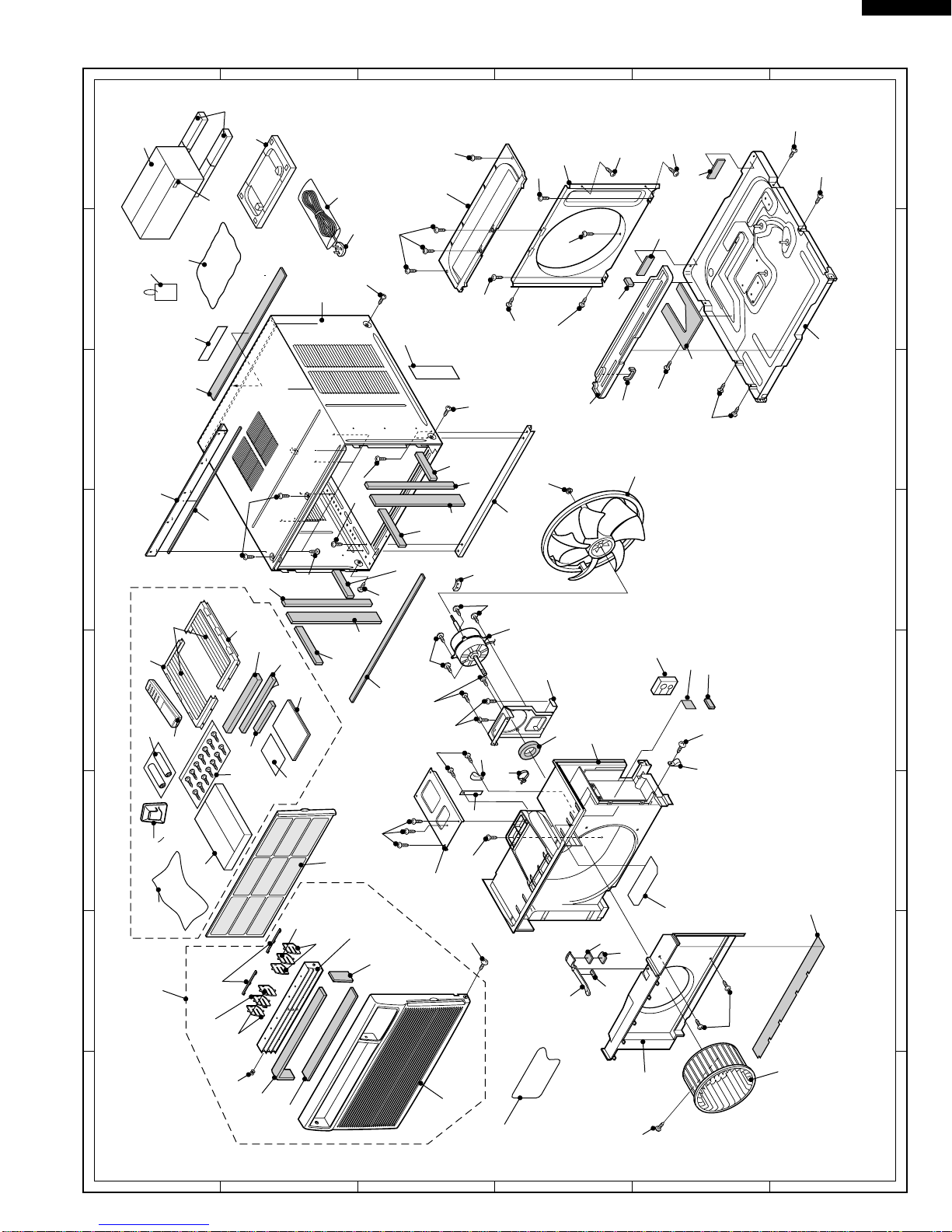
CABINET AND UNIT PARTS
1- 1 CMOTLB026JBEZ Fan motor 1
1- 2 DCHS-A440JBTA Base pan ass’y 1 BC
1- 3 DCAB-A094JBTA Cabinet ass’y 1 BF
1- 4 PSEL-B150JBE0 Cabinet seal 2 AD
1- 5 HPNLCA770JBFA Control panel 1 AF
1- 6 PSEL-C059JBEZ Evaporator insulator 1 AD
1- 7 LANG-A459JBWZ Conecting stay 1 AC
1- 8 LANG-A355JBTA Top inst. Angle 1 AP
1- 9 LHLD-A482JBFZ Thermistor holder 1 AE
1-10 CLEV-A035JBKZ Damper ass’y 1 AE
1-11 NFANPA092JBFZ Propeller fan 1 AV
1-12 NFANSA030JBFZ Centrifugal fan 1 AU
1-13 PFILMA116JBEB Air filter 1 AN
1-14 PFPFPB466JBE0 Insulator 2 AC
1-15 PKESPA082JBTA Condenser shroud 1 AV
1-16 PKESPA083JBFA Orifice 1AQ
1-17 LBND-A046JBE0 Wire fixing band 1 AE
1-18 LCOV-A002JBF0 Shroud cover 1 AM
1-19 PCOV-A320JBP0 Motor cover 1 AC
1-20 PSEL-C057JBEZ Tube insulator 1 AD
1-21 LANG-A356JBTA Bottom inst. Angle 1 AE
1-22 PSKR-A207JBFA Bulkhead 1 BA
1-23 PSRA-A120JBFZ Drain tray 1 AE
1-24 TLAB-C273JBRZ Energy card 1
1-25 TSPC-E150JBRZ Name badge 1
1-26 GWAKPA136JBFB Louver duct 1 AH
1-27 GWAKPA135JBFB Front panel 1 AT
1-28 TLABBA110JBRA SHARP badge 1 AB
1-29 LANGAA038JBFB Left closure frame 1 AK
1-30 LANGAA039JBFB Right closure frame 1 AK
1-31 PPLTPA013JBFB Closure 2AL
1-32 PSPRCA010JBE0 Spring 1AD
1-33 TLABKA564JBE0 Number card 1 AC
1-34 PFPFPB446JBE0 Insulator 1 AC
1-35 CWAK-C095JBKZ Front panel ass’y 1 AX
1-36 MJNTPA074JBFB Louver link 2 AC
1-37 MLOV-A252JBFB Vertical louver A 4 AB
1-38 MLOV-A253JBFB Vertical louver B 2 AC
1-39 PSEL-B360JBE0 Cabinet insulator 1 AB
1-40 PSEL-C064JBEZ Drain tray insulator 1 AC
1-41 PSEL-B361JBE0 Cabinet insulator 2 AE
1-42 PSEL-B367JBE0 Cabinet insulator 2 AC
1-43 PSEL-B516JBE0 Base pan insulator 2 AC
1-44 PFPFPB443JBE0 Insulator 1 AC
1-45 PSEL-C063JBEZ Bulkhead insulator 1 AC
1-46 PSEL-B519JBE0 Angle insulator 1 AD
1-47 PSEL-C056JBEZ Motor seal 1 AE
1-48 LHLDW0367JBE0 Wire holder 1 AA
1-49 LHLDW0368JBE0 Wire holder 1 AA
1-50 PFPFPB528JBE0 Panel insulator 1 AD
1-51 PSEL-A432JBE0 Damper insulator 1 AC
1-52 PFPFPB611JBE0 Insulator 1 AG
1-53 PSEL-B532JBE0 Damper insulator 1 AB
1-54 PSEL-B394JBE0 Panel insulator 1 AB
1-55 PSEL-B560JBE0 Damper insulator 1 AB
1-56 LANG-A507JBWZ Fan motor angle 1 AH
1-57 HPNLCA771JBEA Decoration panel 1 AM
1-58 PSEL-B366JBE0 Panel insulator 1 AD
1-59 PSEL-C104JBEZ Insulator 1 AB
1-60 PSEL-C105JBEZ Cabinet insulator 1 AE
1-61 LHLDW0363JBE0 Wire holder 1 AA
1-62 PSHE-A191JBEZ Sheet 1AE
1-63 LHLD-A356JBE0 Wire holder 1 AE
CONTROL BOX PARTS
2- 1 LBNDKA096JBWZ Capacitor clamp 1 AC
2- 2 LPLTMA128JBW0 Control box cover 1 AK
2- 3 DPLT-A047JBW0 Cont. box angle ass’y 1 AS
REF. NO. PART NO. DESCRIPTION Q'TY CODE

6
AF-R140CX
REF. NO. PART NO. DESCRIPTION Q'TY CODE
HOW TO ORDER REPLACEMENT PARTS
To have your order filled promptly and correctly, please furnish the following information.
1. MODEL NUMBER 2. REF. NO.
3. PART NO. 4. DESCRIPTION
2- 4 QACC-A263JBZZ Power supply cord 1 AT
2- 5 RH-HXA011JBZZ Thermistor 1 AL
2- 6 QW-VZD104JBE0 Lead wire 1 AD
2- 7 QW-IZA036JBZZ Lead wire 1 AS
2- 8 RC-HZA256JBE0 Fan motor capacitor 1 AM
2- 9 RC-HZA407JBZZ Running capacitor 1 AY
2-10 TLABCB621JBRZ Wiring diagram 1
2-11 DPWBFA193JBKZ Control board unit 1 BC
2-12 PSPA-A084JBE0 Spacer 2AC
2-13 PSPA-A085JBE0 Spacer 1AC
2-14 QFS-AA048JBE0 Fuse 1AB
2-15 LBND-A042JBE0 Wire fixing band 4 AC
2-16 RC-HZA443JBZZ Fan motor capacitor 1 AM
CYCLE PARTS
3- 1 PCMPRA373JBEZ Compressor 1 CE
3- 2 PPIPCF655JB1Z Discharge tube 1 AR
3- 3 PPIPCF654JB1Z Suction tube 1 AS
3- 4 RHOG-A198JBZZ Overload relay 1 AT
3- 5 DCON-A167JBKZ Condenser ass’y 1 BT
3- 6 PEVA-A424JBEZ Evaporator 1 BQ
3- 7 GLEG-A105JBE0 Compressor cushion 3 AF
3- 9 PCOV-A321JBE0 Terminal cover 1 AR
3-10 PSEL-A971JBE0 Terminal gasket 1 AN
3-11 DCPY-A234JBKZ Capillary tube ass’y 1 AW
3-12 MSPR-A129JBE0 Cycle spring 1 AD
3-13 PGUM-0034JBE0 Damper rubber 1 AF
3-14 MSPR-A136JBE0 Protector spring 1 AF
3-15 LPLTMA114JBW0 Condenser stay 2 AH
ACCESSORY PARTS
4- 1 TINSEA320JBRZ Operation manual 1 AD
4- 2 PSEL-A349JBE0 Window insulator 1 AE
4- 3 PSEL-A350JBE0 Window insulator 1 AD
4- 4 PSEL-B365JBE0 Window insulator 1 AD
4- 5 TCAD-A351JBEZ Consummer card 1 AB
4- 6 DX-BZA027JBK0 Screws kit 1 AE
4- 7 CRMC-A526JBEZ Remote control 1 AT
4- 8 LHLD-A389JBFB Controller holder 1 AE
4- 9 SSAKAA017YDE0 Bag 1AC
4-10 UBATUA027JBE0 Battery pack 1 AE
PACKING PARTS
5- 1 CPADBA688YDK0 Top pad ass’y 1 AL
5- 2 CPADBA009JBK0 Bottom pad ass’y 1 AT
5- 3 SPAKCB061JBEZ Packing case 1
5- 4 SSAKHA314YDE0 Protect 1AD
5- 5 PPAK-A007JBE0 Inner packing 1 AG
5- 6 TLABMA309JBRZ Feature card 1 AB
5- 7 SSAKAA053YDE0 Bag 1AB
SCREWS AND NUTS
6- 1 XTTSD40P12000 Tapping screw 22 AA
6- 2 LX-BZA236JBE0 Special screw 1 AC
6- 3 XHTSD40P08000 Tap tight screw 8 AA
6- 4 LX-NZA136JBE0 Special nut 2
6- 5 LX-HZA001JBE0 Special screw 6 AB
6- 6 XCTSD40P10000 Tapping screw 19 AA
6- 7 LX-NZA074JBE0 Special nut 1 AB
6- 8 LX-NZA028JBE0 Special nut 3 AB
6- 9 XTPSD40P08000 Tapping screw 3 AA
6-10 XCTSD40P06000 Tapping screw 16 AA
6-11 XBPSD40P12J00 Machine screw 2 AB
6-12 LX-CZA038WRE0 Special screw 6 AA
6-13 XHTSD40P10000 Tap tight screw 2 AA
6-14 XTPSD40P12000 Tapping screw 2

7
AF-R140CX
5-4
6-6
1-38
1-38
1-37
1-37
1-36
1-27
1-10
1-55 1-53
1-51
1-16
1-12
1-22
1-1
1-7
1-39
1-49
1-8
1-28
1-3
1-25
1-2
1-23
1-11
1-21
1-48
1-35
1-26
1-32
1-50
1-58
6-2
5-6
6-1
6-12
1-14
1-14
1-4
1-4
6-10
6-1 6-1
1-63
6-6
6-1
6-1
6-12
6-1 6-12
6-6
6-6
6-12
6-6
6-5
6-5
6-5
6-6
1-18
1-15
6-6
6-6
6-12
6-7
6-1
6-5
6-6 1-19
6-6
6-5
6-1
1-20
1-45
1-59
1-34
1-52
1-60
1-13
1-62
1-54
1-6
1-17
1-47
1-40
1-43
1-43
1-46
1-42
1-41
1-41
4-6
4-5
4-7
4-8
4-4
5-5
5-3
1-33
1-24
5-2 5-1
5-7
2-4
1-30
4-2
4-3
4-1
4-10
4-9 1-29
1-31
1-42
1-56
1-56
1
A
B
C
D
E
F
G
H
B
C
D
E
F
G
H
23456
123456
A
CABINET PARTS

8
AF-R140CX
’02 SHARP CORP. (3U1.60E) Printed in U.S.A.
2-10
6-3
2-2 2-14 6-3
6-3
6-3
6-3
6-13
2-11
6-9
1-5
1-57
2-3
2-12
2-4
2-6
2-4
2-15
6-11
6-1
6-14
6-3
2-7
2-9
2-1
2-8 2-16
2-13
1
A
B
C
D
E
F
G
H
B
C
D
E
F
G
H
23456
123456
A
3-12
3-13
3-1
3-7 6-8
3-3
3-6
6-1
6-3
2-6
6-1
6-1
1-9
2-5
6-1
1-61
3-4
3-14
3-10
1-44
3-9
6-4
3-2
3-5
3-15
6-10
6-10
6-10
2-7
3-11
CYCLE PARTS
CONTROL BOX PARTS
Table of contents
Other Sharp Air Conditioner manuals

Sharp
Sharp UL-C09EA-W User manual

Sharp
Sharp AH-AP18FMF User manual

Sharp
Sharp CVP12PX - Ha Sh 11500 Btu Portable Air... User manual

Sharp
Sharp CV-P10PR User manual

Sharp
Sharp AY-X36RU User manual

Sharp
Sharp AF-P80CX User manual

Sharp
Sharp AY-AP9NRH User manual

Sharp
Sharp AY-AP18GR User manual

Sharp
Sharp AF-06ERL User manual

Sharp
Sharp AF-R80EX User manual

Sharp
Sharp AE-A126J User manual

Sharp
Sharp GX-X18JR User manual

Sharp
Sharp AE-A09CJ User manual

Sharp
Sharp AY-AP9LW User manual

Sharp
Sharp AY-X28MCJ User manual

Sharp
Sharp AH-PN10 User manual

Sharp
Sharp AE-X4M30PU User manual

Sharp
Sharp AH-MP20 User manual

Sharp
Sharp AH-A24FEF User manual

Sharp
Sharp AY-XPC12JHR User manual