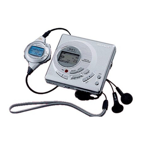
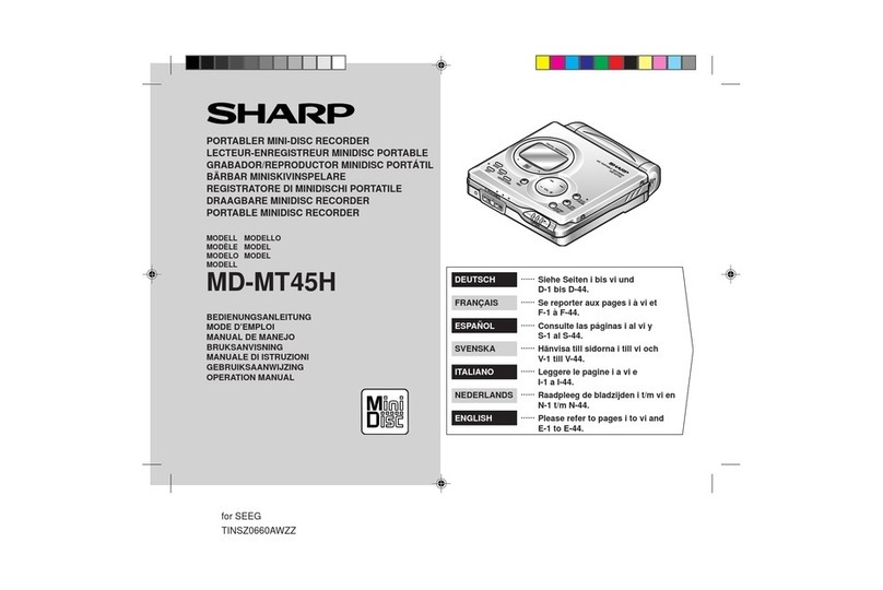
Sharp IM-DR580H(S) User manual

IM-DR580H
CONTENTS
Page
SAFETY PRECAUTION FOR SERVICE MANUAL .......................................................................................................... 2
PRECAUTIONS FOR USING LEAD-FREE SOLDER ...................................................................................................... 3
SPECIFICATIONS ............................................................................................................................................................ 4
NAMES OF PARTS .......................................................................................................................................................... 5
DISASSEMBLY................................................................................................................................................................. 7
REMOVING AND REINSTALLING THE MAIN PARTS .................................................................................................... 9
ADJUSTMENT ................................................................................................................................................................ 10
BLOCK DIAGRAM .......................................................................................................................................................... 31
WIRING SIDE OF P.W.BOARD / SCHEMATIC DIAGRAM ............................................................................................ 33
VOLTAGE ....................................................................................................................................................................... 47
NOTES ON SCHEMATIC DIAGRAM ............................................................................................................................. 48
TYPES OF TRANSISTOR AND DIODE ......................................................................................................................... 48
WAVEFORMS OF MD CIRCUIT .................................................................................................................................... 49
TROUBLESHOOTING .................................................................................................................................................... 51
FUNCTION TABLE OF IC............................................................................................................................................... 54
PARTS GUIDE/EXPLODED VIEW
PACKING METHOD (FOR U.K. ONLY)
SERVICE MANUAL
SHARP CORPORATION
No. SY380IMDR580H
This document has been published to be used
for after sales service only.
The contents are subject to change without notice.
• In the interests of user-safety the set should be restored to its
original condition and only parts identical to those specified be
used.
IM-DR580H(S)
MODEL IM-DR580H(BK)
1-BIT PORTABLE MINIDISC RECORDER

IM-DR580H
– 2 –
Precaution to be taken when replacing and servicing the laser pickup.
The following precautions must be observed during servicing to protect your eyes against exposure to the laser.
Warning of possible eye damage when repairing:
If the AC adaptor or batteries are connected when the top housing (disc cover) of the unit is removed, and the PLAY key is
pressed, the laser will light up during focus access (2-3 seconds). (Fig. 2-1) During the operation, the laser will leak from the
opening between the magnetic head and the mechanical chassis (Fig. 2-2). In order to protect your eyes, you must not look
at the laser during repair. Before repairing be sure to disconnect the AC adaptor and remove the batteries.
Precaution to be taken when replacing and servicing the Laser Pickup.
The AEL (Accessible Emission Level) of Laser Power Output for this model is specified to be lower than Class 1 Requirements.
However, the following precautions must be observed during servicing to protect your eyes against exposure to the laser beam.
(1)Whenthecabinet has beenremoved,the power isturnedonwithout a compactdisc,and the Pickupisona position outerthan
the lead-in position, the Laser will light for several seconds to detect a disc. Do not look into the Pickup Lens.
(2) The Laser Power Output of the Pickup inside the unit and replacement service parts have already been adjusted prior to
shipping.
(3) No adjustment to the Laser Power should be attempted when replacing or servicing the Pickup.
(4) Under no circumstances look directly into the Pickup Lens at any time.
(5) CAUTION - Use of controls or adjustments, or performance of procedures other than those specified herein may result in
hazardous radiation exposure.
SAFETY PRECAUTION FOR SERVICE MANUAL
Magnet Head Laser Beam
Optical Pickup
Main PWB
Spindle motor
Mechanism
Chassis
Figure 2-1 Figure 2-2
For U.K. Except for U.K.
Laser Diode Properties
Material: GaAIAs
Wavelength: 785 nm
Pulse time:
Read mode: 0.8 mW Continuous
Write mode: max 12 mW 0.5S
min cycle 1.5S
Repetition
Laser Diode Properties
Material: GaAlAs
Wavelength: 785 nm
Pulse time:
Read mode: 0.8 mW Continuous
Write mode: max 12 mW 0.5S
min cycle 1.5S
Repetition
WARNUNG - UNSICHTBARE LASERSTRAHLUNG DER
KLASSE 3B WENN GERÄT GEÖFFNET.
UND VERRIEGELUNGEN AUFGEHOBEN. VERMEIDEN SIE,
SICH DER STRAHLUNG AUSZUSETZEN.
ATTENTION - RAYON LASER DE CLASSE 3B INVISIBLE EN
CAS D'OUVERTURE ET DE VERROUILLAGE DÉFECTUEUX.
ÉVTTER UNE EXPOSITION AU FAISCEAU.
VARO - AVATTAESSA JA SUOJALUKITUS OHITETTAESSA
OLET ALTTIINA LUOKAN 3B NÄKYMÄTÖNTÄ
LASERSÄTEILYLLE VARO ALTISTUMISTA SÄTEELLE.
VARNING - KLASS 3B OSYNLIG LASERSTRÅLNING NÄR
DENNA DEL ÄR ÖPPNAD OCH SPÄRREN ÄR URKOPPLAD
UNDVIK EXPONERING FÖR STRÅLEN.
ADVARSEL - KLASS 3B USYNLIG LASERSTRÅLNING VED
ÅBNING, NÅR SIKKERHEDSAFBRYDERE ER UDE AF
FUNKTION UNDGÅUDSÆTTELSE FOR STRÅLNING.
OPEN
OPEN
Magnet Head
Optical Pickup Top Cabinet

IM-DR580H
–3 –
PRECAUTIONS FOR USING LEAD-FREE SOLDER
1. Employing lead-free solder
"All PWBs" of this model employs lead-free solder. The LF symbol indicates lead-free solder, and is attached on the PWBs and
service manuals. The alphabetical character following LF shows the type of lead-free solder.
Example:
Indicates lead-free solder of tin, silver and copper.
2. Using lead-free wire solder
WhenfixingthePWBsolderedwiththelead-freesolder,applylead-freewiresolder.Repairingwithconventionalleadwiresolder
may cause damage or accident due to cracks.
As the melting point of lead-free solder (Sn-Ag-Cu) is higher than the lead wire solder by 40 °C, we recommend you to use a
dedicatedsoldering bit,ifyouarenotfamiliarwithhowtoobtainlead-freewiresolder orsoldering bit,contact ourservicestation
or service branch in your area.
3. Soldering
As the melting point of lead-free solder (Sn-Ag-Cu) is about 220 °C which is higher than the conventional lead solder by 40°C,
and as it has poor solder wettability, you may be apt to keep the soldering bit in contact with the PWB for extended period of
time. However, Since the land may be peeled off or the maximum heat-resistance temperature of parts may be exceeded,
remove the bit from the PWB as soon as you confirm the steady soldering condition.
Lead-free solder contains more tin, and the end of the soldering bit may be easily corrected. Make sure to turn on and off the
power of the bit as required.
If a different type of solder stays on the tip of the soldering bit, it is alloyed with lead-free solder. Clean the bit after every use
of it.
When the tip of the soldering bit is blackened during use, file it with steel wool or fine sandpaper.
Be careful when replacing parts with polarity indication on the PWB silk.
Lead-free wire solder for servicing
Ref No. DescriptionParts No.
PWB-A 92LPWB5593MDSS Main
PWB-B1 92LPWB5484CHRS Multi-Link Station A

IM-DR580H
–4 –
FORACOMPLETEDESCRIPTIONOFTHEOPERATIONOFTHISUNIT,PLEASEREFERTO
THE OPERATION MANUAL.
Specifications for this model are subject to change without prior
notice
SPECIFICATIONS
Power source: DC 1.2 V: Rechargeable Nickel-Metal Hydride Battery (AD-N55BT) x 1
DC 1.5 V: Commercially available, "AA" size (LR6), alkaline battery x 1
DC 3 V: AC adaptor (AC 110 - 240 V, 50/60 Hz), with the multi-link station
Power consumption: 60 mA (AC adaptor)
Output power: RMS: 16 mW (8 mW + 8 mW)
Charging time: Approx. 3.5 hours (90 %)
Approx. 5.5 hours (fully charged)(When using the AC adaptor included with the unit)
Dimensions: Width: 80.1 mm
Height: 16.6 mm
Depth: 72.6 mm
Weight: 120 g with rechargeable battery/95 g without rechargeable battery
USB socket: Multi-link station; exclusive USB socket
Input socket: Main unit; Microphone (powered by the main unit)
Multi-link station; Line/optical digital
Output socket: Main unit; Earphones (impedance: 32 ohms)/remote control
Multi-link station; audio output, speaker output
Type: Portable MiniDisc recorder
Signal readout: Non-contact, 3-beam semiconductor laser pickup
Audio channels: Stereo 2 channels/monaural 1 channel
Frequency response: 20 - 20,000 Hz (±3 dB)
Rotation speed: Approx. 400 - 1,800 rpm CLV (Playback), approx. 400 - 2,700 rpm CLV (Recording)
Error correction: ACIRC (Advanced Cross Interleave Reed-Solomon Code)
Coding: ATRAC/ATRAC3 (Adaptive TRansform Acoustic Coding), 24-bit computed type
Recording method: Magnetic modulation overwrite method
Sampling frequency: 44.1 kHz (32 kHz and 48 kHz signals are converted to 44.1 kHz, and then recorded.)
Wow and flutter: Unmeasurable (less than ±0.001 % W. peak)
Battery life:
Input sensitivity: Output level:
Stereo 2 times long 4 times long
When using the rechargeable
battery (fully charged) included
with the unit
Continuous
recording:
Approx. 8
hours
Continuous
play: Approx.
27 hours
Continuous
recording:
Approx. 12
hours
Continuous
play: Approx.
36 hours
Continuous
recording:
Approx. 15
hours
Continuous
play: Approx.
42 hours
When using a commercially
available, high capacity, "AA"
size (LR6), alkaline battery
Continuous
recording:
Approx. 8
hours
Continuous
play: Approx.
48 hours
Continuous
recording:
Approx. 15
hours
Continuous
play: Approx.
67 hours
Continuous
recording:
Approx. 20.5
hours
Continuous
play: Approx.
75 hours
When using one, commercially
available, high capacity, "AA"
size (LR6), alkaline battery with
the rechargeable battery (fully
charged)
Continuous
recording:
Approx. 20
hours
Continuous
play: Approx.
80 hours
Continuous
recording:
Approx. 30.5
hours
Continuous
play: Approx.
103 hours
Continuous
recording:
Approx. 40
hours
Continuous
play: Approx.
122 hours
The above values are the standard values when the unit is used at an ambient temperature of 25°C.
The continuous recording time is for microphone input when the volume level is set to "VOL 0" and the backlight is set to
"LIGHT OFF".
The continuous play time shows the value when the volume level is set to "VOL 15" and the backlight is set to "LIGHT OFF".
The operating time when using an alkaline battery may be different, depending on the type and manufacturer of the battery,
and on the operating temperature.
"Fully charged" means that the battery is charged for approx. 3.5 hours, and charged for another 2 hours after the battery
indicator disappears.
Reference input
level Input impedance
MIC H 0.25 mV 10 k ohms
MIC L 2.5 mV 10 k ohms
LINE 100 mV 20 k ohms
Specified out-
put Maximum out-
put level Load imped-
ance
Ear-
phones - 8 mW + 8 mW 32 ohms
Audio out-
put 125 mV (-12
dB) - 10 k ohms
Speaker
output 125 mV (-12
dB) *1 - 10 k ohms
*1 When the speaker output selector switch of the multi-link
station is set to MD.
IM-DR580H
–5 –
NAMES OF PARTS
Main unit
1. Stop/Power Off/Hold Button
2. Record Indicator
3. Play/Fast Forward/Fast Reverse/
Volume Button
4. Battery Connection Terminals
5. Multi-link Station Connection Terminal
6. Microphone Input Socket
7. Remote Control/
Earphone Output Socket
8. Open Lever
9. Rechargeable Battery Cover
Multi-link station display
1. Record Indicator
2. TOC Indicator
3. Level Meter
4. Repeat Indicator
5. Random Indicator
6. Synchro Recording Indicator
7. Disc Information Indicator
8. Group Information Indicator
9. Track Information Indicator
10. Battery Indicator
11. Track Protection Indicator
12. Disc Mode Indicator
13. Character/Time Information Indicator
14. Long-Play/Recording Mode Indicator
15. Monaural Mode Indicator
16. Group Indicator
17. My Entry Indicator
1
2
3
4
5
6789
13 5410
11
12
13
14 15 16 17
6
7
8
9
Remote control unit
1. Earphones Socket
2. Record Button
3. Display/Bass Button
4. Playback or Recording Mode
Switching Button
5. Menu Button
6. Volume Buttons
7. Stop/Power Off Button
8. Fast Reverse/Recording Level/
Menu Select Button
9. Play/Pause Button
10. Fast Forward/Recording Level/
Menu Select Button
11. Hold Switch
12. Disc Mode Indicator
13. Total Track Number Indicator
14. Track Number Indicator
15. Character/Time Information Indicator
16. My Entry Indicator
17. Random Indicator
18. Repeat Indicator
19. TOC Indicator
20. Record Indicator
21. Group Indicator
22. Battery Indicator
23. Synchro Recording Indicator
24. Auto Track Mark Record Indicator
25. Alarm Indicator
12
19
13 14 15 16 1817
20 21 22
23
24
25
11
1
8
6710
245
3
9
2

IM-DR580H
–6 –
Multi-link station
1. Playback/Recording Mode Switching/
Charge Button
2. Display/Bass Button
3. Record Button
4. Erase Button
5. Power On or Off/Stop Button
6. Fast Forward/Fast Reverse/
Recording Level/Volume Button
7. Play/Pause Button
8. Enter/USB Switching Button
9. Menu Button
10. Connection Terminal to Main Unit
11. Speaker Output Selector Switch
12. 3 V DC Input Socket
13. USB Socket
14. Optical/Line Input Socket
15. Audio Output Socket
16. Speaker Output Socket
1
2
34
5
6
7
11
10
12 13 14
15
16
8
9

IM-DR580H
–7 –
1 Bottom Cabinet 1. Remove the rechargeable . 7-2
battery cover as indicated
by the arrow.
2. Screw .....................(A1) x5 7-1
2 Main PWB 1. Screw .....................(B1) x2 7-2
2. Screw .....................(B2) x1
3. Flexible PWB..........(B3) x3
3 Top Cabinet 1. Open the Top cabinet. 7-1
2. Screw .................... (C1) x4 7-2
4 MD Mechanism 1. Remove the center cabinet 7-3
as indicated by the arrow.
2. Screw .................... (D1) x1
5 Operation Button 1.
Screw
......................(E1) x1 7-4
Flexible PWB Ass'y
DISASSEMBLY
Cares before disassembling
When assembling the machine after disassembling or
repair, observe the following requirements so as to ensure
safety and performance.
1.Removethebatteriesfromthemachine,andtakeoutthe
mini-disc.
2. When assembling after repair, be sure to position the
wires in the same location.
Use the specified screws to fix the cabinet and the
mechanismunit. Theuseofthescrewswithlength other
than specified may cause contact with the mechanism
unit resulting in malfunction.
3.Whenrepairing,paycloseattentionsonottodamagethe
IC from static electricity.
REMOVAL PROCEDURE
STEP FIGURE Figure 7-1
Figure 7-2
Figure 7-4
Caution:
Carefullyhandle the mainPWBand flexible PWB.Afterremoving the
flexible PWB (1*) for the optical pickup from the connector, do not
touch directly the front end of flexible PWB with your hand so as to
prevent damage of optical pickup by static electricity.
Figure 7-3
Top Cabinet
Bottom Cabinet
EJECT Knob
(A1)x2
ø1.4x1.5mm
(A1)x1
ø1.4x1.5mm
(A1)x1
ø1.4x1.5mm
(A1)x1
ø1.4x1.5mm
(B1)x2
ø1.4x2.5mm
Pull
Pull
Pull
Pull
Pull
Pull
Battery
Cover
Center Cabinet
Top Cabinet
Main PWB
1
2
(B3)x1(1*)
(B3)x1
EJECT Frame
Ass'y
(B3)x1
(C1)x2
ø1.4x1.5mm
(B2)x1
ø1.4x1.5mm
(C1)x2
ø1.4x1.5mm
MD Mechanism
(D1)x1
ø1.4x1.5mm
Center
Cabinet
EJECT Frame
Ass'y
Main Frame Ass'y
(E1)x1
ø1.4x1.5mm
Operation Button
Flexible PWB Ass'y
Top Cabinet
Main Unit

IM-DR580H
–8 –
1 Bottom Cabinet 1. Screw .....................(A1) x4 8-1
2 Multi-Link Station 1. Hook .......................(B1) x3 8-2
B PWB 2. Flat Cable...............(B2) x1
3. Hook .......................(B3) x2
4. Multi-Link Station B PWB
Holder.....................(B4) x1
3 Multi-Link Station 1.
Hook
...................... (C1) x2 8-2
A PWB
REMOVAL PROCEDURE
STEP FIGURE
Multi-Link Station
Figure 8-1 Figure 8-2
(A1)x4
ø2x5mm
Bottom Cabinet
Top Cabinet
Pull
Pull
(B1)x2
(C1)x2
(B3)x2
(B2)x1
(B1)x1
(B4)x1
Bottom Cabinet
Multi-Link Station
A PWB
Multi-Link Station
B PWB

IM-DR580H
–9 –
REMOVING AND REINSTALLING THE MAIN PARTS
Remove the MD mechanism according to the disassembling
methods 1 to 4. (See Page 7.)
Figure 9-1
Figure 9-2
Figure 9-3Figure 9-4
How to remove the spindle motor
(See Fig.
9
-1.)
1. Remove the solder joints (A1) x 4 of flexible PWB.
2. Remove the screws (A2) x 3 pcs., and remove the spindle
motor.
How to remove the lift motor (See Fig. 9-2.)
1. Remove the solder joints (B1) x 2 of lift motor lead wire.
2. Remove the screw (B2) x 1 pc., and remove the lift motor.
Note:
Take care so that the motor gear is not damaged.
(If the gear is damaged, noise is caused.)
How to remove the sled motor (See Fig. 9-3.)
1.Remove thestop washer(C1)x1pc.,andremovethedrive
gear (C2) x 1 pc.
2. Remove the screws (C3) x 2 pcs.
3. Remove the solder joints (C4) x 3 of flexible PWB., and
remove the sled motor.
Note:
Take care so that the motor gear is not damaged.
(If the gear is damaged, noise is caused.)
How to remove the magnetic head ass'y
(See Fig.
9
-4.)
1. Remove the screws (D1) x 2 pcs., of the magnetic head
ass'y and the optical pickup, and remove the solder joints
(D2) x 2 of the head flexible plate.
Note:
Mount carefully so as not to damage the magnetic head.
How to reinstall the optical pickup
(See Fig. 9-4.)
1.Removethescrew(E1) x1pc.,andremove thegripspring.
2.Removethescrew(E2)x1pc.,toremovethethrust spring,
andremovethedrivescrewandtheopticalpickup fromMD
mechanism.
Then, remove the drive screw from the optical pickup.
(A2)x3
ø1.4x1.8mm
MD Mechanism
Spindle Motor
Solder Joints
(A1)x4
Solder Joints
(B1)x2
Lift Motor
MD Mechanism
(B2)x1
ø1.4x3.3mm
(C1)x1
(C2)x1
(C3)x2
ø1.4x1.2mm
Sled Motor
Solder
Joints
(C4)x3
MD Mechanism
(E2)x1
ø1.4x1.2mm
(E1)x1
ø1.4x1.8mm (D1)x2
ø1.4x1.8mm
Thrust
Spring
Optical Pickup
Magnetic
Head Ass'y
Drive Screw
Grip Spring
MD Mechanism
Solder
Joints
(D2)x2

IM-DR580H
–10 –
Entering the TEST mode
1. Setting by main unit or multi-link station operation (in
the stand-by state)
1
Keep holding down the VOLUME + button and press the PLAY
button.
2
With the PLAY button pressed, release the VOLUME + button.
3
With the PLAY button pressed, release the VOLUME –button.
4
Keep holding down the VOLUME –button, release the PLAY
button and then release the VOLUME –button.
5
The test mode stops, and [ T E S T _ ] appears.
2. Setting by remote control operation (in the stand-by
state)
1
Switch the HOLD button from OFF to ON.
2
Hold down the VOLUME –button.
3
With the VOLUME –button pressed, switch the HOLD button
tofromONtoOFF.(Completesteps
1
to
3
within2seconds.)
4
Keep holding down the VOLUME –button and release the
PLAY button.
5
With the PLAY button pressed, release the VOLUME –button
and then release the PLAY button.
6
The test mode stops, and [ T E S T _ ] appears.
7
Press “VOLUME +”to check the version of the microcomputer.
(It is displayed on the remote control only.)
8
Press “VOLUME –” to light up the whole LCD.
1 High reflection disc MMD-110 (TEAC Test MD) 88GMMD-110
2 Low reflection disc MMD-213A (TEAC Test MD) 88GMMD-213A
3 Low reflection disc Recording mini disc UDSKM0001AFZZ
4 Extension cable Performance test (extension cable for motors) QCNWN6936AFZZ
5 Extension relay PWB Performance test (extension relay PWB for motors) RUNTK0613AFZZ
ADJUSTMENT
Test disc
MD adjustment needs two types of disc, namely recording disc (low reflection disc) and playback-only disc (high
reflection disc).
Type Test disc Parts No.
Note: Use the low reflection disc on which music has been recorded.
Figure 10
Leaving the TEST mode
1
PresstheSTOPbuttoninthetestmodestopstate,andwiththe
version displayed or the whole LCD on.
2
Update the rewritable area of EEPROM.
3
Switch to the stand-by mode.
Shipping setting method
(Perform it with the battery removed)
1
Keepholding downthe VOLUME –andthe PLAYbutton on the
main unit, and then plug in the AC adapter.
2
Make sure [INIT] changes to [BYE OK] on the main unit or the
remote control.
Extension Relay PWB
(RUNTK0613AFZZ)
Extension Cable
(QCNWN6936AFZZ)
MD Mechanism
Mechanism Flexible PWB
CN601
Operation Button
Flexible PWB Ass'y
(230)
CN451
CN101
MAIN PWB
Optical Pickup(17)

IM-DR580H
–11 –
1. AUTO 1 Mode
•When the STOP button is pressed while the AUTO1 menu appears
or during automatic adjustment, the mode changes to the TEST
mode stop state. At this time the adjustment value is not output.
•Be sure to adjust, using the specified disc MMD-213A.
•AdjustmentNG;Adjustmentitemoutofrange,focusONfailure, and
adjustment error.
•When the PLAY button is pressed while ADJ. OK is displayed,
AUTO2 is executed.
2. AUTO 2 Mode
•When the STOP button is pressed while the AUTO2 menu appears
or during automatic adjustment, the mode changes to the TEST
mode stop state. At this time the adjustment value is not output.
•AdjustmentNG;Adjustmentitemoutofrange,andadjustmenterror.
•When the PLAY button is pressed while ADJ. OK is displayed,
TEST_PLAY is executed.
3. T-PLAY Mode
•When the STOP button is pressed while the PLAY menu appears,
or in PLAY or continuous playback mode, the mode changes to the
TEST mode stop state.
•When the PLAY button is pressed while the PLAY menu appears,
continuous playback is initiated from the current pickup position.
•WhenevertheMENUbuttonispressedinthePLAYmenu,thetarget
address changes as follows.
0032 →03C0 →0700 →08A0 →0950 →0032 →•••
When the PLAY button is pressed while a target address is dis-
played, continuous playback is performed after searching that
address.
•Each time the REC button is pressed while the PLAY mode target
address is displayed, the digit which is changed by pressing the
FORWARD/REVERSE button is changed as follows.
0032 →0032 →0032 →0032 →•••
•When the FORWARD button is pressed in the PLAY mode target
address is displayed, the digit of address specified by the REC
button is set to +1h. (0 to F)
•When the REVERSE button is pressed in the PLAY mode target
address is displayed, the digit of address specified by the REC
button is set to -1h. (0 to F)
* When the fast FORWARD/REVERSE button is kept pressed, the
selected digit number continuously varies in a cycle of 100 ms.
1. AUTO 1 Mode •Perform preliminary automatic adjustment.
•If the combination of mechanism and pickup PWB
has been changed, be sure to start from AUTO1.
2. AUTO 2 Mode •Perform ATT (attenuator) automatic adjustment.
•Perform continuous playback. (error rate display,
jump test.)
3. T-PLAY Mode •Continuous playback from the specified address is
performed.
•1 jump or 10 jumps and manual movement.
•C1 error rate display (pit section), ADIP error rate
display (groove section).
•The temperature correction is performed only when
servo start is performed, but the posture correction
is not performed during continuous playback.
4. T-REC Mode •Continuous record from the specified address is
performed.
•Change of record laser output. (servo gain is also
changed according to laser output.)
•The temperature correction is performed only when
servo start is performed, but the posture correction
is not performed during continuous recording.
5. MANU 1 Mode •Temperature is displayed.
•Seeing the displayed adjustment value, perform
preliminary manual adjustment.
(Error rate indication, jump test.)
6. MANU 2 Mode •Temperature is displayed.
•Seeing the displayed adjustment value, perform
ATT (attenuator) manual adjustment.
•Continuous playback is performed.
(error rate display, jump test.)
7. E_DATA display •Error information is displayed.
Mode •Error information is initialized.
8. NORMAL Mode •The mode is changed from the TEST mode to the
normal mode without adjustment.
•In the normal mode the internal operation mode,
memory capacity, etc. areindicated.
•In the normal mode both temperature correction
and posture correction are performed.
9. EEPROM Mode •Factors of digital servo are changed manually.
•Cut-off frequency of BASS1, BASS2 and BASS3 is
changed manually.
•Temperature detection terminal voltage is
measured, and the reference value is set.
•Defaults are selected and set.
•Setting of EEPROM protect area is updated.
Test Mode
•IfyoupresstheMENUbuttonontheremotecontrolinthecontinuous
playback mode, the number of jumps changes as follows.
1 →10 →100 step →1 •••
* After the number of jump lines is indicated for one second, the
address indication is restored. [ T R _ ]
•When the FORWARD button is pressed in the continuous playback
mode,thespecified number oflines isjumped in theFWD direction.
•When the REVERSE button is pressed in the continuous playback
mode, the specified number of lines is jumped in the REV direction.
* When the FORWARD/REVERSE button is held down, jump is
repeated every approx. 100 ms.
•Whenever the MENU button is pressed in the continuous playback
mode, the indication changes as follows.
* Pre-mastered disc
Continuous playback [ S Q ]
(SUBQ address indication)
↓
Continuous playback (C1 error indication) [
C E ]
↓
Continuous playback [ S Q ]
(SUBQ address indication)
* Recordable disk
Continuous playback [ A P ]
(ADIP address indication)
↓
Continuous playback (C1 error indication) [
C E ]
↓
Continuous playback (ADIP error indication)[ A E ]
↓
Continuous playback [ b ]
(Integrating jitter indication)
↓
Continuous playback [ A P ]
(ADIP address indication)
Operation in each TEST mode
To enter each mode from the test mode STOP "TEST"
Press the MENU button (on the remote control or multi-link station).
Select each mode using the SKIP UP/DOWN button.

IM-DR580H
–12 –
4. T-REC Mode
•When the STOP button is pressed while the REC menu appears, or
in the REC mode or continuous record mode, the mode changes to
the TEST mode stop state.
•Wheneverthe MENUbutton ispressed in theREC menu, thetarget
address changes as follows.
0032 →03C0 →0700 →08A0 →0950 →0032 →•••
When the PLAY button is pressed while a target address is dis-
played, continuous playback is performed after searching that
address.
•Whenever the REC button is pressed in the REC mode target
address is displayed, the digit which is changed by the VOLUME +/
–button changes as follows.
0032 →0032 →0032 →0032 →•••
•When the FORWARD button is pressed in the REC mode target
address is displayed, the digit of address specified by the REC
button is set to +1h. (0 to F)
•When the REVERSE button is pressed in the REC mode target
address is displayed, the digit of address specified by the REC
button is set to -1h. (0 to F)
* When the FORWARD/REVERSE button is held down, the setting
changes continuously, one cycle being 100 ms.
•When the VOLUME +/–button is pressed in the REC mode or
continuous record mode, the laser record power changes.
(Servo gain changes also according to record power.)
* After the laser record power is indicated for one second, the
address indication is restored. [ R P W _ ]
•: Address
•: Laser power cord
•Operation is disabled if the premastered disc or disc is in miserase-
protected state.
5. MANU 1 Mode
•AdjustmentitemtobemadeinAUTO1modeisperformedmanually.
•When the VOLUME + button is pressed during adjustment, the
setting increases, and the new setting is output.
•When the VOLUME –button is pressed during adjustment, the
setting decreases and the new setting is output.
•If the VOLUME +/–button is held down, the setting changes
continuously with 100 ms cycle.
*In this operation, the setting change is performed for each digit.
The digit is changed by pressing the REC button.
•If the setting is within the allowable range, the RND display lights.
•WhentheSTOPbuttonispressedduringMANU1menuormeasure-
ment or adjustment, the state is changed to the TEST mode stop
state.
6. MANU 2 Mode
•AdjustmentitemtobemadeinAUTO2modeisperformedmanually.
•When the VOLUME + button is pressed during adjustment, the
setting increases, and the new setting is output.
•When the VOLUME –button is pressed during adjustment, the
setting decreases and the new setting is output.
•If the VOLUME +/–button is held down, the setting changes
continuously with 100 ms cycle.
*In this operation, the setting change is performed for each digit.
The digit is changed by pressing the REC button.
•If the setting is within the allowable range, the RND display lights.
•WhentheSTOPbuttonispressedduringMANU2menuormeasure-
ment or adjustment, the state is changed to the TEST mode stop
state.
•When the PLAY button is pressed in B-ATT set state, the mode is
changed to the continuous playback mode.
•Asfor operationduringcontinuous playbackrefer to "T-PLAYmode
explanation".
7. E_DATA display Mode
•Reversing when REVERSE button is pressed.
•When the STOP button is pressed while the error data indication
menu appears or during error data indication, the mode changes to
the TEST mode stop state.
•Error data E0 is the latest error.
•ErrorwhichoccurredintheTESTmodeisalsostoredinthememory.
•When the GROUP button is pressed while the error data indication
menu appears, the error data is initialized.
[ C L E A R _ ]
: Error Code
8. NORMAL Mode
•When the STOP button is pressed while the NORMAL menu
appears, the mode changes to the TEST mode stop state.
•Indication during operation Indication of memory capacity on main
unit LCD
(Multi-Link Station)
[ _ _ ] + Level meter
: Internal mode
: Address (Cluster section)
: Address (Sector section)
(Remote Control)
[ T N O _]
: Internal mode
: Address (Cluster section)
•Selection of sound volume, BASS, etc. is possible. (without indica-
tion)
•Recording is also possible.
•If the STOP button is pressed during operation in the NORMAL
mode,theNORMAL modeiscancelled,andthepoweristurnedoff.

IM-DR580H
–13 –
[1] Measurement, calculation and setting procedure.
1
Set the TEST mode.
2
Activate the “Temp”menu in the “EEPROM”mode.
•In the test mode stop state, press the MENU button,
SKIP-DOWN button (three times), and PLAY button
(twice) in this order.
•“TM$$%%”appears. ($$ = temperature code, %% =
temperature reference value)
3
“TPin##”willappearwhenpressingtheSKIP-UPbutton
once. (## = TEMP input AD value)
4
Calculatethe temperature correctionvalueby referring
to the ambient temperature and the “Temperature
measurement value correction table”.
5
Calculatethetemperaturereferencevalueaccordingto
the formula below.
•Temperature reference value = Microcomputer TEMP input
AD value + Temperature correction value
6
Press the SKIP-DOWN button once to display “TM$$%%”.
Press the VOLUME –/+ button to set “%%”to the value
calculated in step
5
.
7
Check if the temperature code ($$) is the same as in the
“Temperature measurement value correction table”
Ambient
temperature Temperature
correction
+ 8 oC ~ +10 oC - 05 h + 8.5 oC
+11 oC ~ +13 oC - 04 h + 11.6 oC
+14 oC ~ +16 oC - 03 h + 14.6 oC
+17 oC ~ +19 oC - 02 h + 17.6 oC
+20 oC ~ +22 oC - 01 h + 20.6 oC
+23 oC ~ +25 oC±00 h + 23.6 oC
+26 oC ~ +28 oC + 01 h + 26.6 oC
+29 oC ~ +31 oC + 02 h + 29.6 oC
+32 oC ~ +34 oC + 03 h + 32.6 oC
Center
temperature
Ambient
temperature Temperature
correction Center
temperature
- 8 oC ~ +10 oC 08 h + 0.5 oC
+ 3 oC ~ +21 oC 07 h + 12.0 oC
+14 oC ~ +33 oC 06 h + 23.6 oC
+26 oC ~ +44 oC 05 h + 35.0 oC
[2] Temperature measurement value correction table.
Temperature reference setting method.
[3] Temperature code identification.
13 h : Adjustment servo retraction excessive retrial
16 h : C. IN detection time-over
17 h : A, B, E, F, and TCRSO offset measurement value out of
tolerable range
21 h : Focus retraction completion allowable time-over
22 h : Unable to activate the spindle motor
23 h : Track search completion allowable time-over
32 h : P-TOC read failure
42 h : U-TOC read failure
44 h : U-TOC write data write disabled/read check error
45 h : U-TOC write test failure
52 h : SD write data write disabled
72 h : EEPROM data read check sum error
73 h : Record head drive disabled (by EJECT lever)
82 h : Power overvoltage detection
83 h : The temperature sensor output error
91 h :
Ambient temperature is higher that the allowable temperature
Explanation of error history code
Can't READ (*)
* = f : Focus pulled
a : Servo adjustment
s : Track search
r : TOC information reading
p : Spindle start
Er-MD (**)
** = 80
“Er-MD80”appearswhenEEPROMdatacannotbereadcorrectly
(inconsistency of data and the checksum results).
EEPROM or communication paths including the microcomputer
may be defective.
WhenyouchangeEEPROM,resetdatabyreferringtotheservice
manual.
** = 41
“Er-MD41”appears when writing U-TOC fails. (Only recorders)
(Reading of the written data reveals errors.)
The record head, the recording signal generator circuit including
system LSI or the pickup laser may be defective.
TOC FORM (*)
* = t_ : TNO information
a_: Address information
Ln: Pointer information
(n = 0, 1, 2 or 4: UTOC sector number)
Error messages

IM-DR580H
–14 –
EEPROM DATA LIST (EEPROM version : d)
F G 1 _ 24 H
F G 2 _ 58 H
F G 3 _ 90 H
F F 0 _ 10 H
F F 1 _ 70 H
F F 2 _ E5 H
F f 0 _ 10 H
F f 1 _ 48 H
F f 2 _ EA H
f F 0 _ 10 H
f F 1 _ 18 H
f F 2 _ EC H
F Z H _ ED H
F L n _ 09 H
F L p _ 06 H
D J G _ 0C H
F S S _ 0C H
F T S _ 18 H
F S B _ 18 H
F T B _ 28 H
F G M _ 66 H
T V G _ C0 H
T O 1 _ 2A H
T O 5 _ 2A H
T O R _ 2A H
P L E _ 8B H
R F T _ 00 H
F L 1 _ 0F H
F L 2 _ 1F H
F G C _ 5A H
T V R _ C0 H
Item display Set values
Focus setting
S P G _ 0C H
S P 1 _ 18 H
P G 2 _ 18 H
R G 2 _ 1C H
R G 3 _ 1C H
P G M _ C0 H
S P 1 _ 10 H
S P 2 _ 60 H
S P 3 _ F2 H
S P 4 _ F2 H
S 4 2 _ F2 H
S 4 3 _ F8 H
S P 5 _ 10 H
S L 1 _ 7F H
S L 2 _ 7F H
S D 2 _ 7F H
S P K _ EB H
M P 1 _ 14 H
M P 2 _ 01 H
S P L _ 60 H
S P B _ 11 H
S R i _ 30 H
S R m _ 26 H
S R o _ 1E H
S B R _ 60 H
O S L _ 14 H
P J G _ 34 H
B T R _ 78 H
S W T _ 44 H
Item display Set values
Spindle setting

IM-DR580H
–15 –
H Q 1 _ 90 H
H Q 2 _ 90 H
H S G _ 11 H
H S O _ FF H
L Q 1 _ 90 H
L Q 2 _ 90 H
L S G _ 12 H
L S O _ 00 H
G Q 1 _ 98 H
G Q 2 _ 84 H
G S G _ 12 H
A L S _ 3F H
R C N _ 00 H
E Q R _ 00 H
S K S _ 7F H
S K L _ 7F H
S L C _ 42 H
S T L _ 08 H
S T M _ 42 H
S T E _ A6 H
S D V _ 60 H
S J P _ 03 H
W T m_ 18 H
S R V _ 59 H
S L T _ 58 H
M V S _ 0A H
S L S _ 28 H
S K E _ 25 H
S D E _ 23 H
B P E _ 31 H
B P W _ 97 H
B P 1 _ 43 H
B R E _ 94 H
B R W _ 34 H
S R S _ 00 H
S H C _ 42 H
S H S _ 28 H
T G 1 _ 17 H
T G 2 _ 40 H
T G 3 _ 66 H
T F 0 _ 10 H
T F 1 _ 70 H
T F 2 _ E0 H
T f 0 _ 10 H
T f 1 _ 40 H
T f 2 _ E4 H
t F 0 _ 10 H
t F 1 _ 20 H
t F 2 _ E8 H
T F S _ 00 H
T B o _ 20 H
T B t _ 34 H
T K o _ 20 H
T K t _ 32 H
T D o _ 67 H
T D t _ 0E H
S C o _ 00 H
S C t _ 3A H
S C m _ 48 H
C L p _ 24 H
C L r _ 38 H
J P I _ 0E H
T K L _ 40 H
T H P _ 02 H
T H G _ 02 H
T 0 P _ F0 H
T 0 G _ EF H
T 1 P _ 18 H
T K n _ 11 H
T K N _ 26 H
T K T _ 16 H
T D T _ 16 H
T D L _ 1F H
T G C _ 66 H
T G M _ 66 H
S P W _ 0F H
T R 0 _ 00 H
T R 1 _ 00 H
Item display Set values
Tracking setting
Item display Set values
Sled setting
Digital EQ setting
Item display Set values

IM-DR580H
–16 –
C T 0 _ 03 H
C T 1 _ 01 H
C T 2 _ BB H
C T 3 _ 50 H
U S A _ 18 H
R C E _ 94 H
X 2 T _ FF H
S D F _ 1F H
F B O _ FC H
B H S _ 01 H
F B L _ 16 H
M C 2 _ 00 H
M C 4 _ 00 H
L 2 H _ 81 H
L 4 H _ 80 H
B S 0 _ 3A H
B S 1 _ 98 H
B U 0 _ 01 H
B D 0 _ 05 H
B D 1 _ DC H
B M K _ 1E H
C S T _ 65 H
I J U _ 81 H
I J D _ 55 H
M C T _ A1 H
E R C _ 5A H
C V 0 _ 27 H
C V 1 _ 10 H
S S K _ E9 H
A C T _ 60 H
C 1 E _ 52 H
A D E _ C0 H
L C V _ 12 H
w E 3 p 05 H
w E 3 g 00 H
w E A _ 16 H
w E F _ 00 H
R C 0 _ D7 H
R C 1 _ D6 H
R 2 0 _ 80 H
R 2 1 _ 20 H
R 4 0 _ BF H
Item display Set values
Control setting
Item display Set values
R 4 1 _ 02 H
G U P _ 1B H
S C G _ 00 H
K 1 0 _ 0F H
K 1 1 _ 8E H
A T N _ 0C H
A T U _ 0A H
A H D _ 4D H
A L D _ 60 H
A C T _ 01 H
P L G _ 22 H
C R N _ 00 H
S V V _ 80 H
A V V _ 70 H
V S N _ BB H
B S 0 _ 00 H
B S 1 _ 00 H
B S 2 _ 50 H
B S 3 _ 00 H
B S 4 _ 00 H
B S 5 _ 00 H
B S 6 _ 00 H
B S 7 _ 22 H
B S 8 _ 00 H
Item display Set values
BASS setting
C O K _ 28 H
F A T _ C0 H
T A T _ 3E H
C A T _ 40 H
F A B _ 64 H
Item display Set values
ADJ. SET setting

IM-DR580H
–17 –
R M 3 3 01 H
R M 3 4 7E H
R M 3 5 6E H
R M 3 6 E2 H
R M 3 7 01 H
R M 3 8 FC H
R M 3 9 EB H
R M 3 A 5A H
R M 3 B 0B H
R M 3 C 12 H
R M 3 D 0B H
R M 3 E 18 H
R M 3 F 7B H
R M 4 0 C7 H
R M 4 1 E8 H
R M 4 2 AE H
R M 4 3 07 H
R M 4 4 B7 H
R M 4 5 AF H
R M 4 6 07 H
R M 4 7 B7 H
R M 4 8 B0 H
R M 4 9 07 H
R M 4 A D9 H
R M 4 B 1F H
R M 4 C 28 H
R M 4 D 00 H
R M 4 E FC H
R M 4 F E9 H
R M 5 0 17 H
R M 5 1 0B H
R M 5 2 00 H
R M 5 3 00 H
R M 5 4 00 H
R M 5 5 00 H
R M 5 6 00 H
R M 5 7 00 H
R M 5 8 00 H
R M 5 9 00 H
R M 5 A 00 H
R M 5 B 00 H
R M 5 C 00 H
R M 5 D 00 H
R M 5 E 00 H
R M 5 F 00 H
R M 6 0 00 H
R M 6 1 00 H
R M 6 2 00 H
R M 6 3 00 H
R M 6 4 00 H
R M 0 0 37 H
R M 0 1 32 H
R M 0 2 36 H
R M 0 3 42 H
R M 0 4 18 H
R M 0 5 0B H
R M 0 6 E2 H
R M 0 7 B6 H
R M 0 8 7E H
R M 0 9 8F H
R M 0 A 44 H
R M 0 B 36 H
R M 0 C 4E H
R M 0 D 52 H
R M 0 E 7E H
R M 0 F 8F H
R M 1 0 1F H
R M 1 1 BD H
R M 1 2 E7 H
R M 1 3 02 H
R M 1 4 38 H
R M 1 5 05 H
R M 1 6 6A H
R M 1 7 05 H
R M 1 8 C7 H
R M 1 9 01 H
R M 1 A AE H
R M 1 B 17 H
R M 1 C FC H
R M 1 D BA H
R M 1 E E2 H
R M 1 F 0B H
R M 2 0 04 H
R M 2 1 0E H
R M 2 2 DC H
R M 2 3 1B H
R M 2 4 FC H
R M 2 5 1D H
R M 2 6 DC H
R M 2 7 0E H
R M 2 8 10 H
R M 2 9 0B H
R M 2 A 5A H
R M 2 B E5 H
R M 2 C 7E H
R M 2 D 3E H
R M 2 E CB H
R M 2 F 01 H
R M 3 0 7E H
R M 3 1 7E H
R M 3 2 CC H
Item display Set values
ROM Correction setting Item display Set values

IM-DR580H
–18 –
(During the spare style automatic adjustment.)
(During the focus balance adjustment.)
(During the adjustment that ATT is automatic.)
Normality completion.
(Adjustment completion.)
(Continuance is regenerating.)
It confirms that an address proceeds.
PLAY
PLAY
A U T O 1
Do the following when replacing the mechanism, the pickup, the
EEPROM (IC402), the LSI (IC201) or the main PWB unit.
A D J . O K
A T 2
A T 1
Before you replace EEPROM, be sure to set the EEPROM set value to the latest version.
(Note) After that, be sure to perform the shipment setting.
(The battery indicator starts to operate correctly after you complete the setting.)
The indication of RANDOM
A P # # # #
Indication disappears.
All the supply of the power supply is turned off.
B Y E O K
STOP is 2 pushed.
Remote controller MODE button.
A D J . O K
Enter the test mode, move the pickup to the most internal periphery and execute AUTO1.
(Use the disc of MMD-213A.)
PLAY is pushed.
Normality completion.
(In such cases as the battery.)

IM-DR580H
–19 –
Performance mode = Normal
Playback volume = 28
LINE REC volume = 30
Microphone REC volume = 20
Resume setting = Cancellation
: To the test mode stop ([Test mode menu])
Volume
Up
Volume
Down : Version indication 2 seconds
EEPROM version
Test Mode Start ·Completion method
All the lighting
T E S T
•Starting method of the test mode
(1) When using the main unit and remote control
When the following operation is performed using the remote control while the product is in the
stand-by state (the display is off), the test mode starts.
Switch the "HOLD" button from OFF to ON.
When the [VOLUME -] button is pressed and held, switch the [HOLD] button from ON to OFF.
(Perform these steps within 2 seconds.) When the [VOLUME -] button is held down, press the
[PLAY[ button. When the [PLAY[ button is held down, release the [VOLUME -] button.
Then release the [PLAY] button.
(2) When using the multi-link station
Place the main unit on the multi-link station.
When the [VOLUME +] button is pressed and held while the product is in the stand-by state,
press the [PLAY] button.
When the [PLAY] button is held down, release the [VOLUME +] button and press the
"VOLUME-" button.
When the [VOLUME -] button is held down, release the [PLAY] button. Then release the
[VOLUME -] button.
: LCD all the lighting two seconds
Destination
Program version
•How to cancel the test mode
T E S T
B Y E
B Y E O K
POWER OFF
: Test mode stop
: [OK] or [NG]
Check the microcomputer RAM and EEPROM with
the contents of the preliminary adjustment.
Pickup position initialisation
EEPROM contents renewal.
STOP
Indication after the start :

IM-DR580H
–20 –
: Test mode stop
: Pre-automatic adjustment menu
: ATT auto adjustment menu
: EEPROM setting menu
MENU
T E S T
Slide external
periphery move Slide internal
periphery move
Change of Test Mode Menus
A U T O 1
A U T O J
A U T O 2
SKIP UP SKIP DOWN
SKIP UP SKIP DOWN
SKIP DOWN
SKIP UP SKIP DOWN
SKIP UP SKIP DOWN
SKIP UP SKIP DOWN
SKIP UP SKIP DOWN
T R E C
T P L A Y
SKIP UP SKIP DOWN
SKIP UP SKIP DOWN
: Error history display menu
E E P R O M
SKIP UP SKIP DOWN
SKIP UP
SKIP DOWN
SKIP UP
* When the [STOP] button is pressed in specific menu, the "TEST MODE STOP" state is set.
* When the [VOLUME +] button is pressed in the "TEST MODE STOP" state, the program version
is displayed for 2 seconds.
* When the [VOLUME -] button is pressed in the "TEST MODE STOP" state, all the displays
appear for 2 seconds.
: Pre-manual adjustment menu
: ATT manual adjustment menu
: Continuous playback menu
M A N U 1
: Continuous record menu
M A N U 2
: Test mode normal play menu
E D A T A
N O R M A L
: Digital input signal monitor menu
SKIP UP SKIP DOWN
SKIP UP SKIP DOWN
: Pre-adjustment value check menu
D i n M o n
SKIP UP SKIP DOWN
: ATT adjustment value check menu
R S L T 1
R S L T 2
This manual suits for next models
1
Table of contents
Other Sharp CD Player manuals

Sharp
Sharp MD-MT90W User manual

Sharp
Sharp MD-MT15S User manual

Sharp
Sharp QT-CH88H User manual

Sharp
Sharp WQ-CH600L User manual

Sharp
Sharp MD-MT877H User manual

Sharp
Sharp CD-C75HR User manual

Sharp
Sharp WQ-CH900H User manual

Sharp
Sharp WQ-CD15H User manual

Sharp
Sharp MD-MT190H User manual

Sharp
Sharp DX-55HM User manual

Sharp
Sharp MD-MT877H User manual

Sharp
Sharp MD-MS701H2 User manual

Sharp
Sharp MD-T60H User manual

Sharp
Sharp WQ-CH800H Quick start guide

Sharp
Sharp MS722 - MiniDisc Recorder - Metallic User manual

Sharp
Sharp IM-DR420H User manual

Sharp
Sharp WQ-CD220L User manual

Sharp
Sharp MD-MT290H User manual

Sharp
Sharp MD-MT99H User manual

Sharp
Sharp CD-BK147V User manual