R-677 - 10
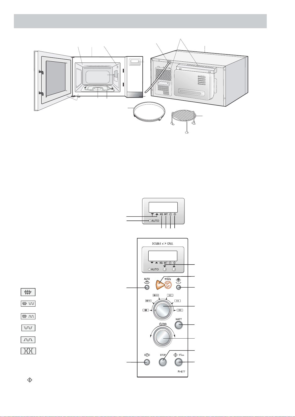
TOP GRILL MODE
In this mode, the food is cooked by the grill heating
element (top grill). Select the TOP GRILL mode with the
COOKING MODE selector. Enter the cooking time by
rotating the TIME/WEIGHT dial. When the START button
is pressed, the following operations occur:
Figure O-3(a) on page 33
1. The relay RY1 + RY3 + RY5 are energized.
2. Thenumbersofthedigitalreadoutstartthecountdown
to zero.
3. Then the grill heating element (top), turntable motor,
oven lamp and fan motor are energized.
4. Now, the food is grilled by the grill heating element.
5. Uponcompletion of the selected cooking time, audible
signal sounds and the contacts of relays RY1 + RY3
are opened, then the grill heating element (top), turn-
table motor and oven lamp are de-energized.
6. TherelayRY5staysclosedforfive(5)minutes,andthe
fan motor operates.
BOTTOM GRILL MODE
In this mode, the food is cooked by the bottom heating
element.SelecttheBOTTOMGRILLmodewiththeCOOK-
INGMODEselector.Enterthecookingtimebyrotatingthe
TIME/WEIGHT dial. When the START button is pressed,
the following operations occur:
Figure O-3(b) on page 33
1. The relay RY1 + RY4 + RY5 are energized.
2. Thenumbersofthedigitalreadoutstartthecountdown
to zero.
3. Then the bottom heating element, turntable motor,
oven lamp and fan motor are energized.
4. Now,the food is grilled by thebottomheatingelement.
5. Uponcompletion of the selected cooking time, audible
signal sounds and the contacts of relays RY1 + RY4
areopened,then the bottom heatingelements,turnta-
ble motor and oven lamp are de-energized.
6. TherelayRY5staysclosedforfive(5)minutes,andthe
fan motor operates.
TOP AND BOTTOM GRILL MODE
In this mode, the food is cooked by both the grill heating
element(topgrill)and bottom heating element.Selectthe
TOP AND BOTTOM GRILL mode with the COOKING
MODE selector. Enter the cooking time by rotating the
TIME/WEIGHT dial. When the START button is pressed,
the following operations occur:
Figure O-3(c) on page 34
1. The relay RY1 + RY3 + RY4 + RY5 are energized.
2. Thenumbersofthedigitalreadoutstartthecountdown
to zero.
3. Then the grill heating element (top), bottom heating
element,turntablemotor,ovenlampandfanmotorare
energized.
4. Now, the food is grilled by the grill heating element
(top) and the bottom heating element.
5. Uponcompletion of the selected cooking time, audible
signal sounds and the contacts of relays RY1 + RY3 +
RY4 are opened, then the grill heating element (top),
bottom heating element, turntable motor and oven
lamp are de-energized.
6. TherelayRY5staysclosedforfive(5)minutes,andthe
fan motor operates.
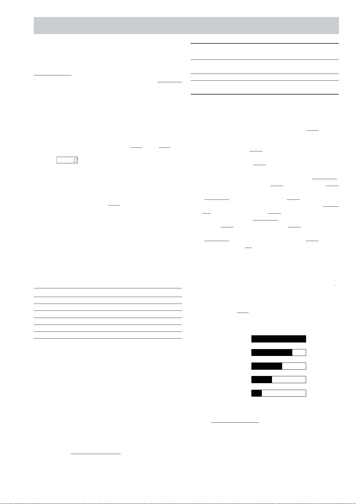
DUAL COOKING CONDITION
The oven has two dual cooking mode. One is MICRO-
WAVE AND TOP GRILL mode and other one is MICRO-
WAVE AND BOTTOM GRILL mode. In both modes, the
relayRY2operatesintermittentlywithina48secondstime
base as shown below.
Power level ON time OFF time
100% 48 sec. 0 sec.
70% 36 sec. 12 sec.
50% 26 sec. 22 sec.
30% 16 sec. 32 sec.
10% 8 sec. 40 sec.
MICROWAVE AND TOP GRILL MODE (DUAL 1)
Inthismode,thefoodiscookedbymicrowaveandthegrill
heatingelement(top).SelecttheMICROWAVEANDTOP
GRILLmodewiththeCOOKINGMODEselectorandthen
select the power level with the WATT button. Enter the
cookingtimebyrotatingtheTIME/WEIGHTdial.Whenthe
START button is pressed, the following operations occur
(Fig. O-4(a)):
1. The relay RY1 + RY2 + RY3 + RY5 are energized.
2. Thenumbersofthedigitalreadoutstartthecountdown
to zero.
3. The grill heating element (top), high voltage trans-
former, turntable motor, oven lamp and fan motor are
energized.
4. Now, the food is cooked by the microwave and grill
heating element (top).
5. Uponcompletion of the selected cooking time, audible
signal sounds and the contacts of relays RY1 + RY2 +
RY3 are opened, then the grill heating element (top),
high voltage transformer, turntable motor and oven
lamp are de-energized.
6. TherelayRY5staysclosedforfive(5)minutes,andthe
fan motor operates.
MICROWAVE AND BOTTOM GRILL MODE (DUAL 2)
In this mode, the food is cooked by microwave and the
bottom heating element. Select the MICROWAVE AND
TOPGRILLmodewiththeCOOKINGMODE selectorand
thenselectthepowerlevelwiththeWATTbuttonEnterthe
cookingtimebyrotatingtheTIME/WEIGHTdial.Whenthe
START button is pressed, the following operations occur
(Fig . O-4(b)):
1. The relay RY1 + RY2 + RY4 + RY5 are energized.
2. Thenumbersofthedigitalreadoutstartthecountdown
to zero.
3. Thebottomheatingelement,highvoltagetransformer,
turntable motor, oven lamp and fan motor are ener-
gized.
4. Now,the food iscooked bythe microwave andbottom
heating element.
5. Uponcompletion of the selected cooking time, audible
signal sounds and the contacts of relays RY1 + RY2 +
RY4 are opened, then the bottom heating elements,
high voltage transformer, turntable motor and oven
lamp are de-energized.
6. TherelayRY5staysclosedforfive(5)minutes,andthe
fan motor operates.
OPERATION SEQUENCE CONT...


 User manual")