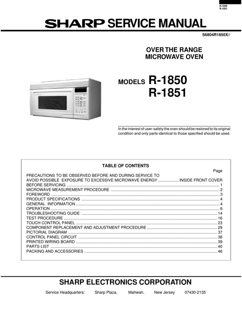
Sharp R-8000E User manual

-_ - .q----7- ~-‘
SHARP SERVICE MANUAL
f’
SHARP
CONVECTION MICROWAVE OVW-
R-%OOOE
In the interests of user-safety the set should be restored to its original
qdition and only parts identical to those specified used.
RATION - ’ ’

SERVICE MANUAL
SHARP
R-8000E
FOREWORD
This service manual is prepared to provide Sharp service
personnel with complete service information on Sharp
Convection Microwave Oven.
Basic, general information for Sharp Microwave Ovens is
given in the GENERAL service manual.
Therefore, to permit them to give satisfactory customer
service, it is recommended that service personnel first study
the entire text of GENERAL manual, and then carefully
study this book.
CAUTION
MICROWAVE RADIATION
Personnel should not be exposed to the microwave energy
which may radiate from the magnetron or other microwave
generating devices if it is improperly used or connected.
All input and output microwave connections, waveguides,
flanges, and gaskets must be secured.
Never operate the device without a microwave energy
absorbing load attached.
Never look into an open waveguide or antenna while the
device isenergized.
SHARP CORPORATION
OSAKA, JAPAN

TABLE OF CONTENTS
Page
FOREWORD ....................................................................... 1
CNUTION, MICROWAVE RADIATION .................................................... 1
THUMB INDEX..................................................................... 1
CHAPTER I PRODUCT DESCROPTION ................................................... 4
Specifications ................................................................... 4
Features of Control Panel ........................................................... 5
CHAPTER11 OPERATION ............................................................. 6
NormalCookingSequence.. ........................................................ 6
Microwave.Cooking ............................................................. 6
Convection Cooking. ............................................................. 6
Description of Operating Sequence ..................................................... 6
OffCondition ................................................................. 6
IdleCondition.. .............................................................. 7
Microwave Cooking Condition. ..................................................... 7
FullPowerCooking ........................................................... 7
Defrost, Simmer, Roast or Warm Cooking ............................................ 7
Preheating Condition ............................................................ .8
Convection Cooking Condition ..................................................... .8
Combination Cooking Condition .................................................... .8
Description and Function of Components ................................................ 14
Variable Cooking Control. ....................................................... .14
MicrowaveTimer...............................................................l 5
ConvectionTimer..............................................................l 5
DoorOpenMechanism...........................................................l 6
Upper and Lower Latch Switches. .................................................. .16.
Monitor Switch (United Kingdom and Australia models): .................................... 16
Thermostat ................................................................ ..17
Convection Cooking System ...................................................... .18
SheathHeater.................................................................l 8
CHAPTER111 SERvIC~G.............................................................l 9
Troubleshooting Guide. ........................................................... .l9
OffCondition..............................’...................................l 9
IdleConition.................................................................l 9
Microwave Cooking Condition. ......................... -: .......................... .20
Convection Cooking Condition ..................................................... .2l
Test Procedures. ................................................................ .22
.. Magnetron Assembly Test. ....................................................... .22
Power Transformer Test ......................................................... .22
Upper Latch Switch Test ........................................................ .22
Lower Latch Switch Test ........................................................ .22
Vari-switchTest...............................................................2 2
Vari-motor Test ............................................................... .22
Sheath Heater Test ............................................................ .23
ThermostatTest..................................:............................2 3
CamSwitchTest...............................................................2 3
Monitor Switch Test ........................................................... .23
2

CHAPTER IV COMPONENT REPLACEMENT AND ADJUSTMENT PROCEDURES. . . . . . . . . . . . . . . . . . . . .
Warning.......................................................................2 4
Outer Case Removal. ............................................................. .24
OvenLampRemoval....................................................~.........2 4
Power Transformer Removal ........................................................ .24
RectifierRemoval................................................................2 4
Hight Voltage Capacitor Removal. .................................................... .24
Turntable Motor Removal. ......................................................... .25
Surge Limiting Relay Removal (Continental Europe only). .................................... .25
FanMotorRemoval...........:-...................................................2 6
Magnetron Assembly Removal. ...................................................... .26
Convection Motor Assembly Removal (Sheath Heater and Convection Motor) ....................... .26
Control Panel and Components Removal ................................................ .28
Convection Timer ........................................................... .28
CamSwitch................................................................2 8
Thermostat ................................................................. .28
Vari-motor Assembly. ........................................................ .28
MicrowaveTimer........:....................................................2 8
Convection Lamp, Heater Lamp, Microwave Lamp ..................................... .28
Cookswitch................................................................2 8
Upper Latch Switch and Monitor Switch (United Kingdom and Australia) Removal. ................... .30
Lower Latch Switch Removal ....................................................... .30
Upper and Lower Latch Switches and Monitor Switch (United Kingdom and Australia) Adjustment ......... .3 1
Door Replacement and Adjustment ................................................... .32
MICROWAVE MEASUREMENT. . . . . . . . . . . . . . . . . . . . . . . . . . . . . . . . . . . . . . . . . . . . . . . . . . . . . . . . . .33
SCHEMATIC DIAGRAM (Continental Europe Model) . . . . . . . . . . . . . . . . . . . . . . . . . . . . . . . . . . . . . . . . . . .34
PICTORIAL DIAGRAM (Continental Europe Model) . . . . . . . . . . . . . . . . . . . . . . . . . . . . . . . . . . . . . . . . . . .35
SCHEMATIC DIAGRAM (South Africa Model). . . . . . . . . . . . . . . . . . . . . . . . . . . . . . . . . . . . . . . . . . . . . . . .36
PICPORIAC DIAGRAM (South Africa Model). . . . . . . . . . . . . . . . . . . . . . . . . . . . . . . . . . . . . . . . . . . . . . . .37
SCHEMATIC DIAGRAM (Australia Model) . . . . . . . . . . . . . . . . . . . . . . . . . . . . . . . . . . . . . . . . . . . . . . . . . .38
PICTORIAL DIAGRAM (Australia Model) . . . . . . . . . . . . . . . . . . . . . . . . . . . . . . . . . . . . . . . . . . . . . . . . . .39
SCHEMATIC DIAGRAM (United Kingdom Model) . . . . . . . . . . . . . . . . . . . . . . . . . . . . . . . . . . . . . . . . . . . . .40
PICTORIAL DIAGRAM (United Kingdom Model) . . . . . . . . . . . . . . . . . . . . . . . . . . . . . . . . . . . . . . . . . . . . .41
PACKING AND ACCESSORIES . . . . . . . . . . . . . . . . . . . . . . . . . . . . . . . . . . . . . . . . . . . . . . . . . . . . . . ...42
PARTS LIST.......................................................................43
3

CHAPTER I
PRODUCT DESCRIPTION
SPECIFICATIONS
Power requirements 22OV/24OV
50Hz
Power consumption
Microwave output power
Convection output power
Case dimensions
Width
Height
BPfi
Cooking cavity dimensions
Width
Height
&Ph
Turntable diameter
Control complement
Weight
Single phase, 3 wire earthed
1.3kW (Microwave), 1.4kW(Convection)
650W (2 litre water load)
1.3kW nominal of Sheath Heater
552mm
395mm including feet
500mm
340mm
255mm
36Ornr-n
325mm
Cook Switch
60 min. Dual Speed Timer (Microwave Timer)
120min. Single Speed Timer (Convection Timer)
Variable Cooking Control
Repetition Rate:
25 : FULL POWER (HIGH)
-&I-
Full power through out the cooking time.
: ROAST (MEDIUM HIGH)
&r
23 sec. ON, 7sec. OFF, approx. 70% of full power
: SIMMER (MEDIUM)
l.Er
16.5 sec. ON, 13.5 sec. OFF, approx. 50% of full power
. . : DEFROST (MEDIUM LOW)
9.8 sec. ON, 20.2 sec.
& : WARM (LOW) OFF, approx. 30% of full power
5 sec. ON, 25 sec. OFF, approx. 10%of full power
Convection Temperature Control:
40°C 90°C to 250°C
Approx. 35kg
“u ---,A v----, -.-^ -_- -_

FEATURES OF CONTROL PANEL
El 23
fi tf
??J
6% 2%
1
0
Indicator Lamp for Convection Cooking (Orange)
------Timer for Convection Cooking
Temperature (Heater) Indicator Lamp (Red)
Temperature Control for Convection Cooking
Indicator Lamp for Microwave Cooking (Green)
Variable Cooking Control
7&r : FULL POWER (HIGH)
A- : ROAST (MEDIUM HIGH)
fr : SIMMER (MEDIUM)
A-
*.. : DEFROST (MEDIUM LOW)
t.
liT : WARM (LOW)
I Timer for Microwave Cooking
Cooking Start Button
Door Open Button
5

CHAPTER II
OPERATION
NORMAL COOKING SEQUENCE
Microwave Cooking:
1. Place the food to be cooked in the oven and close the
door firmly.
2. Set the variable cooking control for a desired position.
3. Set the microwave timer for a desired cooking time.
The oven lamps will come on and the fan motor will
rotate immediately.
Note: When setting the timer for less than 1 minute,
turn the past 2 minutes position and back to
the correct time.
Note: Make sure that the convection timer is at “0”
position.
4. Push the Cooking Start button. The microwave lamp
will glow to indicate the oven is in the cook cycle, and
the turntable motor, microwave timer and vari-motor
will operate.
Note: If the oven door is opened by pushing the open
button during the cook cycle, the oven will go
out of the cook cycle (no microwave energy)
and the microwave timer wilI stop. This is done
so the exact cooking time remains on the timer.
To restore cooking operation, the door must be
closed and the Cooking Start button must be
pushed again.
5. At the end of the cook cycle (timer returned to “O”),
microwave lamp will go out and the timer bell will
ring. The oven will stop supplying the microwave
energy.
Convection Cooking:
1. Set the convection temperature control for a desired
position.
2. Set the convection timer for a desired cooking time.
The oven lamps will come on and the fan motor will
rotate immediately.
Note: When setting the timer for less than 10minutes,
turn the past 20 minutes position and back to
the correct time.
Note: Make sure that the microwave timer is at “0”
position.
3.
The oven will stop supplying the heater energy.
Push the Cooking Start button.
The convection lamp will glow to indicate the oven is
in the convection cooking cycle, and-the turntable
motor, convection timer, sheath heater and heater
lamp will operate.
Note: The heater lamp will light until the setting
temperature reaches. This heater lamp turns on
and off repeatedly to hold the preheat setting
temperature.
Note: If the oven door is opened by pushing the open
button during the convection cook cycle, the
oven will go out of the cook cycle (no heater
energy) and the convection timer will stop.
This is done so the exact convection cooking
time remains on the timer.
To restore convection cooking operation, the
door must be closed and the Cooking Start
button must be pushed again.
4. The heater lamp turns on and off repeatedly when
oven temperature has reached at the setting tempera-
ture.
5. Place the food to be cooked in the oven and close the
door firmIly.
6. Set the convection timer for a desired cooking time,
and Cooking Start button must be pushed again.
The convection timer now return to zero.
7. At the end of the convection cook cycle (convection.
timer return to “O”), convection lamp will go out and
the timer bell will ring.
DESCRIPTION OF OPERATING SEQUENCE
The following is a complete description of component
fanctions during the four stages of oven operation. OFF CONDITION
Note: The following operations refer to the Continental
Europe Model and the others are quite similar in
each model.
With both timers (microwave and convection) dial at “0”
position and the door closed, no components in the oven
will operate, Figure 1. But the oven lamps and fan motor
will turn on with the door opened.
‘L
x”K-% *-h--d..... _L_ -

IDLE CONDITION
Closing the door activates both door latch switches; upper
latch switch and lower latch switch.
Microwave:
Selecting a cooking time closes the microwave timer
contacts (7) -(8) leading to the oven lamps and fan
motor, therefore the oven lamps and fan motor turn
on, Figure 2.
Convection:
Selecting a cooking time closes the convection timer
contacts 0-a leading to the oven lamps and fan
motor, therefore the oven lamps and @n motor turn
on, Figure 3.
MICROWAVE COOKING CONDITION
1. FULL POWERCOOKING
The variable cooking control is set to Full Power (-tff)
position and cooking time is selected by turning the
microwave timer.
Note: Make sure that the convection timer is at “0”
position.
t When the “Cooking Start” button is pushed, the
following operations occur: (Figure 4).
l-l. The microwave timer contacts (7)(8) and cook
switch are closed.
l-2 The microwave timer, microwave lamp, vari-motor
and surge limiting relay are energized through the
convection timer contacts @ -0 and microwave
timer contacts (2) - (3).
1-3 The-220 volts A.C. is supplied to a primary wind-
ing of the power transformer through the
vari-switch, and the surge limiting relay contacts.
l-4 The power transformer converts 3.15 volts AC.
output on the filament winding and approxi-
mately 2,000 volts A.C. on the high voltage
winding.
l-5 The 3.15 volts A.C. output from fildment winding
heats the magnetron filament.
1-6 The 2,000 volts A.C. output from the secondary
winding is sent to a voltage doubler circuit con-
sisting of a high voltage capacitor and a rectifier.
The 2,000 volts AC. is converted to approximate-
ly 4,000 negative D.C. voltage (peak to peak)
by the voltage doubler circuit and sent to the
magnetron assembly.
1-7 The negative 4000 volts D.C. is applied to the
cathode of the magnetron tube. This causes it
to oscillate and produce a 2450 MHz cooking
frequency.
1-8 The RF energy produced by the magnetron
tube is channeled through a waveguide and then
into the oven cavity where the food is placed
to be cooked.
1-9 Upon completion of the selected cooking time,
the timer bell rings once. And the timer contact
are deactivated. The oven reverts to the OFF
condition.
Note: On the Australia and United Kingdom models.
The monitor switch is electrically monitoring the
operation of the upper latch switch and is
mechanically associated with fhe door so that it
will function in the following sequence.
(1) When the door opens from closed position,
the upper and lower latch switches first
operate to open their contacts, and then the
monitor switch contacts close.
(2) When the door is closed from open position,
the monitor switch confacts first open, and
then the contacts of the upper and lower latch
switches close. I
In the case upper latch switch fails with its contacts
closed when the door is opened, the monitor switch
will form a short circuit through the fuse and the upper
latch switch.
2. DEFROST, SIMMER, ROAST OR WARM
COOKING.
When the “cooking start” button is pushed and the
variable cooking control is set to “DEFROST (-&- )”
“SIMMER ( -&- )“, “ROAST ( -& )” or “WARM
( -& )“, the following operations occur.
2-l. Above l-l operation occurs.
2-2 The vari-motor rotates at two (2) revolutions
per minute. In case the cooking control is set to
“DEFROST ( -&--)“, the 220 volts A.C.issupplied
to the power transformer intermittently through
the vari-switch which is operated, at approx. 10
seconds ON and 20 seconds OFF repetition rate
by means of a cam linked to the vari-motor shaft.
The repetition rate for others are as follows;
WARM (fi) : approx. 5 seconds ON, 25
seconds OFF
SIMMER(A) : approx. 16 seconds ON, 14
seconds OFF
ROAST (A): approx. 23 seconds ON, 7
seconds OFF
2-3 The 2,000 and 3.4volts A.C. outputs are produced
when the 220 volts AC. is supplied to the power
transformer.
2-4 Then above 1-2, 1-3, 14, l-5,1-6, l-7,1-8 and 1-9
operations occur.
7
PREHEATING CONDITION
Set the preheating temperature by turning the temperature
control knob (at 90°C to 25O”C), and preheating time at
20 minutes.
When the “Cooking Start” button is pushed the following
operations occur: (Figure 5).
1. The contacts @ - @ of convection timer and cook
switch are closed. The fan motor, oven lamps and
turntable motor are energized.
2. The contacts @ -@ of convection timer is closed.
The convection timer and convection lamp are energiz-
ed.
3. The 220 volts A.C. is supplied to the sheath heater and
heater lamp through the thermostat.
4. In case the temperature control is set at 40°C:
The contacts (COM)-(NC) of cam switch closed to
provide a current path to the convection motor
through the thermostat.
In case the temperature control is set at 90°C to
250°C:
The contacts (COM)-(NO) of cam switch closed to
provide a current path to the convection motor
through the convection timer contacts 0 - @ .
5. When the temperature of the therm0 rod which is
mounted to the back oven cavity, rises above the
selected temperature, the circuit to the sheath heater
and heater lamp are de-energized by the thermostat.
But other components remain in operation. When the
temperature of the therm0 rod drops below the
selected temperature, the 220 volts A.C. is supplied to
the sheath heater and heater lamp.
6. The preheat temperature has been reached.
The sheath heater and heater lamp will cycle on and
off by thermostat to maintain the selected tempera-
ture .
CONVECTION COOKING CONDITION
When the preheat temperature is reached, open the door
and place the food to be cooked in the oven. Then set the
desired convection temperature and cooking time by
turning the temperature control knob and convection
timer.
When the “Cooking Start” button is pushed, the following
operations occur:
1. The convection and heater lamps light.
2. The fan motor, oven lamps, t.urntable motor, convec-
tion timer, convection motor and sheath heater are
energized.
3. Upon completion of the selected cooking time, the
timer bell rings, and the all contacts of the convection
timer are deactivated. The oven reverts to the OFF
condition.
Note: When both microwave and convection timers are
set, convection cooking takes place first.
In this case, the microwave operation will begin
automatically when the convection timer returns to
“0” position.
COMBINATION COOKING CONDITION
Set the preheating temperature and preheating time at 20
minutes.
When “Cooking Start” button is pushed, the following
operations occur:
1. The convection and heater lamps light.
2. The fan motor, oven lamps, turntable motor, convec-
tion timer, convection motor and sheath heater are
energized.
3. The 220 volts AC. is supplied to the sheath heater.
4. When the oven temperature reaches to the selected
temperature, the convection lamp and sheath heater
will cycle on and off by thermostat.
5. Now, the oven is preheating condition;
When the preheat temperature is reached, open the door
and place the food to be cooked in the oven. Then set the
desired convection temperature and cooking time, desired
microwave cooking control and cooking time.
When the “Cooking Start” button is pushed, the following
operations occur:
1. First the oven is operating the convection cooking.
2. When the timer returns to zero, the timer bell will ring
and microwave timer will operate automatically.
3. Now, the oven is operating the microwave cooking,
4. At the end of the microwave cook cycle, the timer bell
will ring and all components are de-energized.
-..--x
\ -~N.-“d ‘. . --__- -~~- - ---.

220V 50Hz
FUSE
26OV T6.3A
LINE
BYPASS
CAPACITOR I1LINE
RESISTOR BYPASS
A CAPACITOR
FAN MOTOR
LOWER
LATCH
SWITCH
NOTE: CONDITION
1. DOOR CLOSED
CONVECTION 0
TURNTABLE
1IA-.-A-
L---- -___ ---1
----r-- ------- ---- -- MICRO
A nnwv2nlAiauc TllhRCD &
TIMER
I.II”b .“..A” L I IIWL”
4c ,, CONTACTS
MICROWAVE (3)
LAMP
0 I’
TIMER
1 CONTACTS
0
THERMOSTAT
THERM0
( 1
SWITCH
((2)
-01JT
VARI-MOTOR -- --I ’ I
0 1
SURGE
LIMITING
RESISTOR
SURGE LIMITING RELAY
L!
-
------ , POWER TRANSFORMER
RECTIFIER VOLTAGE
t MAGNETRON
Figure 1. Oven Schematic-off condition
9

220V 50Hz
LINE
BYPASS
CAPACITOR a
J-7
r
LOWER
LATCH
SWITCH
‘% ‘r, -\ cc, ___.. -. ‘. ;
r---- ---- 1
I@--; 1
I E
e
I
I- ____ -----J m
FUSE
250V T6.3A
RESISTOR
FAN MOTOR
- RESISTOR
Ty-T LINE ACROSS
CAPACITOR
&
n+
MAGNETRON
THERM0 CUT.
h LINE
BYPASS
7 CAPACITOR
-OUT
ZOM
-1
INC
OVEN LAMP
TURNTABLE
UPPER
LATCH
SWITCH
I COOK
CONVECTION 0
-- -1 0’ SWITCH
THERMOSTAT
MICROWAVE
LAMP
VARI-MOTOR ----- 0
LJ SURGE
_ _ ---- ------- LIMITING
RESISTOR
SURGE LlMlTlhiG RELAY -I
POWER TRANSFORMER
Figure 2. Oven Schematic-Idle Condition (Microwave)
10

220V 50Hz
\“‘I
M
r---- ---_ 1
I ! N
WIW I 1
I FUSE
25OV T6.3A
LINE
BYPASS
CAPACI TOR , FAN MOTOR
LINE ACROSS
CAPACITOR
LINE
BYPASS
CAPACITOR
LOWER
LATCH
SWITCH
SCHEMATIC
NOTE: CONDITION
OF OVEN
1. DOOR CLOSED
2. CONVEC. TIMER “ON”
3. TEMP. CONTROL
“#400C”
i
OVEN LAMP
r-l
_ COM
-- I TURNTABLE
MOTOR
MAGNETRON
THERM0 CUT-O\
UPPER
CONVECTION
, LAMP I---
L I- u-l
________ ,-I ____ ---- ----- ii MICRO
MICROWAVE TIMER TIMER
,, CONTACTS
MICROWAVE (4) (5) (3)
_____----mm--- VARI-SWITCH
SURGE
__----- ----- LIMITING
RESISTOR
SURGE LIMITING RELAY
RECTIFIER CAPACITOR
RECTIFIER
-- -----
POWER TRANSFORMER
MAGNETRON
Figure 3. Oven Schematic-Idle Condition (Convection)Figure 3. Oven Schematic-Idle Condition (Convection)
1111
LAMP
VAR I-MOTOR
JT

220V 50Hz
- RESISTOR
LINE
BYPASS
CAPACITOR
L
RESISTOR LINE ACROSS
CAPACITOR
FAN MOTOR
LOWER
LATCH
SWITCH
I
OVEN LAMP
MICROWAVE TIMER
MICROWAVE
LAMP
0 r--d7
L---~--l
VAR I-MOTOR
0
L--------------
SCHEMATIC
NOTE: CONDITION
OF OVEN
1. DOOR CLOSED
2. MICRO. TIMER “ON”
3. VARIABLE COOKING”
CONTROL
““FULL POWER”
4. COOK SWITCH”ON”
SURGE LIMITING RELAY -.
I -_ ~--
-- -
RECTIFIER CAPACITOR -
MAGNETRON
IFUSE
250V T6.3A
LINE
BYPASS
A CAPACITOR
/ MAGNETRON
THERM0 CUT-OUT
.
UPPER
LATCH
SWITCH
COOK
SWITCH
: CONVEC.
I TIMER
! CONTACTS
0
THERMOSTAT
(THERM “>SWITCH
(2)
_ MICRO
TIMER
CONTACTS u
(3)
- VARI-SWITCH
SURGE
LIMITING
RESISTOR
POWER TRANSFORMER
Figure 4. Oven Schematic-Microwave Cooking Condition (Full Power)
12

220V 50Hz
LINE
BYPASS A3 <
CAPACITOR
SCHEMATIC
NOTE: CONDITION
OF OVEN
1. DOOR CLOSED
2. CONVEC. TIMER “ON”
3. TEMP. CONTROL
“90°C to 25O’C”
4. COOK SWITCH “ON”
r---- ---- 1
I
FUSE
250V T6.3A
- 1
RESISTOR
TyT LINE
.
: RESISTOR LINE ACROSS
CAPACITOR BYPASS
A CAPACITOR
7 FAN MOTOR -
hEE[ 5%OUT
r I T 1 AT-t-”
- TURNTABLE LPiIb”
SWITCH
COOK
I ; LAMP r--------- -1 I
; SHEATH THERMOSTAT
0 ; HEATER 4) (THERM0
SWITCH )
; CONVECTION \J
Y 1MOTOR COM?:
I
; HEATER
1LAMP /------
MICROWAVE
LAMP
MICROWAVE TIMER ’
(
(
I--VI
VAR I-MOTOR -
CONTACTS
(3)
- 7
SURGE LIMITING RELAY 1
1
.- VARI-SWITCH
r-iii
SURGE
LIMITING
RESISTOR
POWER TRANSFORMER
Figure 5. Oven Schematic-Convection Cooking Condition
13 /’ ’

DESCRIPTION AND FUNCTION OF COMPONENTS
VARIABLE COOKING CONTROL
The variable cooking control consists of the vari-motor, the power transformer intermittently within a 30
vari-switch, gear, select lever bracket assembly, etc. seconds time base. A half (l/2) of full power would be
the purpose of the vari-motor is to rotate a cam which approx. 16 seconds of the switch on the 14 seconds of off
is going to turn the vari-switch on and off within 30 time. The following chart shows the vari-switch operation
seconds time base. in the various modes.
The vari-switch is operated ON by the cam lever and cam
which are linked to the vari-motor shaft. If the variable
cooking control is set at WARM, DEFROST, SIMMER
or ROAST position, 220/240 volts A.C. is supplied to
Note: The ON/OFF time ratio does not correspond with
the percentage of microwave power, because approx.
2 seconds are needed for heating of the magnetron
filament.
_ ON
5 Seconds OFF (25 sec.) Microwave Power = Approx. 10%
ON
*: DEFROST
. (MEDIUM LOW) 9.8 Seconds OF F (20.2 sec.) Microwave Power = Approx. 30%
ON
SIMMER
: (MEDIUM) 16.5 Seconds OFF (13.5sec.) Microwave Power = Approx. 50%
ON
-25 ROAST
: (MEDIUM HIGH) 23 Seconds OFF (7sec.) Microwave Power = Approx. 70%
25: FULL
POWER . Microwave Power = 100%
(HIGH)
k-30 Seconds N
14
‘Y ‘I-, - I.__^. _.._ . __. - %.

MICROWAVE TIMER
Timer switch contacts: Timer motor:
The timer switch contacts are mechanically opened or
closed by turning the timer knob located on the timer
motor shaft. The contacts (7)-(8) control the current
path to the oven lamps and fan motor, etc.
The contacts (2)-(3) control the current path to the
microwave timer, microwave lamp, vari-motor and power
transformer through the vari-switch.etc.
Timer is single speed type: cook time from 0 to 120
minutes may be selected with the timer. The dial is divided
in 5 minutes intervals. The timer motor is energized through
the cook switch, upper latch switch and convection timer
contacts @ - 0. When the timer reaches the 0 point on
the scale, both timer contacts @ - @ and @ -0 open
the circuit to the fan motor, oven lamps, turntable motor,
convection timer, convection lamp, sheath heater, con-
vection motor and heater lamp, and the convection cook
cycle stops.
Timer bell:
The bell striker is mechanically driven by the timer motor
and rings once at the end of the microwave cook cycle.
Timer motor:
Timer is dual speed type: cook time from 0 to 60 minutes
may be selected with the timer.
Continental Europe:
Up to 5 minutes the dial is divided in 15 second inter-
vals. From 5 minutes to 10 minutes the dial is divided
in 30 second intervals. From 10 minutes to 60 minutes
the dial is marked off in 5 minute intervals.
‘United Kingdom, Australia and South Africa:
Up to 10 minutes the dial is divided in 15 second.inter-
vals. From 10 minutes to 60 minutes the dial is marked
off in 5 minute intervals.
The timer motor is energized through the cook switch,
upper latch switch, convection timer contacts @ - @ and
microwave timer contacts (2)-(3). When the timer reaches
the 0 point on the scale, both timer contracts (7)-(8) and
(2)-(3) open the circuit to the fan motor, oven lamps,
turntable motor, microwave timer, microwave lamp and
vari-motor, and the microwave cook cycle stops.
CdN-VECTION TIMER
Timer switch contacts:
The timer switch contacts are mechanically opened or
closed by turning the timer knob located on the timer
motor shaft. The contacts @ - @ control the current
path to the oven lamps and fan motor, etc.
The contacts @ - @ opens and then contacts @ - @ is
closed. The contacts @ - @ control the current path to
the convection timer, convection lamp, sheath heater,
convection motor and heater lamp through the thermostat
when temperature is set 90” to 250°C.
Timer bell:
The bell striker is mechanically driven by the timer motor
and rings once at the end of the convection cook cycle.
Timer shaft:
Cams are inserted into the timer shaft. When the timer shaft
is wound up, these cams operate to close a damper so
that no hot air will be allowed to leak out of the oven
cavity. When the timer reaches 0 point, the damper is
opened by the cam.
Figure 6 Convection Timer Desired Time Set
15

DOOR OPEN MECHANISM
The door can be opened by pushing the open button on
the control panel, refer to Figure 7.
Pushing the open button, the open plate on the open
device pushes the door lever on the door.
Therefore, the lower and upper latch heads remove
upwards, and then those latch heads are released from the
lower and upper latch hooks.
Now, the door can be opened.
UPPER AND LOWER LATCH SWITCHES
The upper latch switch is mounted in the upper latch hook
and the lower latch switch is mounted in the lower latch
hook. They are activated by the latch heads on the door.
When the door is opened, the switches interrupt the circuit
to all components except the oven lamps and fafi motor.
A cook cycle cannot take place until the door is firmly
closed thereby activating both switches.
MONITOR SWITCH (UNITED KINGDOM AND
AUSTRALIA MODELS)
The monitor switch mounted on the upper latch hook is
activated (the contacts opened) by the latch head on the
door while the door is closed. The switch is intended
to render the oven inoperative by means of blowing the
fuse when the contacts of the upper latch switch fail to
open when the door is opened.
Functions;
1. When the door is opened, the monitor switch contacts
close (to the ON condition) due to their being a
normally closed. At this time the upper latch switch is
in the OFF condition (contacts open) due to its being a
normally open contact switch.
2. As the door goes to a closed position, the monitor
switch contacts are first opened and then the upper latch
switch contacts close. (In case of opening the door, each
of the two switches operate inversely.)
3. If the door is opened and the upper latch switch con-
tacts fail to open, the fuse blows simultaneously with
the closing of the monitor switch contacts.
CAUTION: BEFORE REPLACING A BLOWN FUSE,
TEST THE UPPER LATCH SWITCH AND
MONITOR SWITCH FOR PROPER OPERA-
TION (REFER TO THE TEST PROCEDURE
ON PAGES 22 AND 23.)
Note: The
‘Door Open
Button
Figure 7. Door Open Mechanism
nitor
itch
Latch
Switch
monitor switch is provided on United
Kingdom and Australia Models.
Figure 8. Latch Switches and Monitor Switch
16

THERMOSTAT
The thermostat is composed of thermo-rod, shaft, contacts
etc. The oven cavity temperature is sensed through apushed
hole provided at the cavity rear by means of the thermo-rod.
Furthermore, the oven cavity temperature can be preset
by turning the temperature control knob to a desired
position.
Setting temperature range : 4O”C,90°C to 250°C
Thermostat contacts connected to sheath heater, convection
motor and heater lamp.
1. During cook cycle:
The thermostat contacts close and above components
are energized.
2. During hold temperature: -.
When the cavity temperature reached the preset degree,
the thermostat contacts open and close again several
minutes later to thereby maintain the cavity tempe-
rature at the preset degree as shown in Figure 9.
Thermostat contacts repeat ON-OFF operation by
action of the thermo-rod so that they open at the
moment, when the oven cavity temperature reached
the preset degree, and close again several minutes later
to thereby maintain the cavity temperature at the
preset degree as shown in Figure 9.
Setting temperature
(9OOC to 25OOC)
Tembrature into o&n kvity
I
I ’ ’ : ’ ,
f----~~~~ I : I ’
(40°C 1
SHEATHHEATER
and HEATER LAMP
*
I ON
I ,
; I I I Time&--
I I I ’
’ i ;
I t I ’ I
I
’ ;ONi jONi !ON
SHEATHHEATER
CONVECTION MOiOR; oFF ‘; oFF “w” oFF OWNOFF
and HEATER LAMP
Function of Thermostat
This thermostat actuates their contacts by changing the
pressure of oil filled in a capillary tube according to tempe-
rature rise.
Clockwise turn (High Temp.) of the temperature control
knob will expand gap-A and anticlockwise turn (Low
Temp.) of the same will reduce gap-A, as shown in Figure
10. Normally, contact is in ON position.
With cook, oil temperature in the thermo-rod rises and
the oil is pressurized by capillary tube.
When the cavity temperature reached the preset degree,
the boss pushes the depressor by pressure from the
capillary tube to thereby turn the contacts to OFF
position.
When the oven cavity temperature comes down below
the preset degree, the oil pressure is reduced and the
depressor returns to its original position to thereby
turn the contact to ON position.
ON-OFF operation of the contacts is repeated till
cooking time elapses to “0”.
/ 6°C
Fixed
THERMO-
STAT
Temperature control shaft
Movable contact plate
Figure 9. Figure 10. Thermostat Function
17

CONVECTION COOKING SYSTEM
This oven is designed with a hot air heating system where
food is not directly heated up by the sheath heater, but is
instead heated by forced circulation of the hot air produced
by the sheath heater.
The air heated by the sheath heater is circulated through
the convection passage provided on the outer casing of the
oven cavity by means of the convection fan which is driven
by the convection motor. It then enters the inside of oven
through the vent holes provided on the around and back
side of the oven. Next, the hot air heats up the food on the
turntable and leaves the oven cavity through the vent hole
in the center of the back cavity ceiling. Without leaving the
oven, this hot air is reheated by the sheath heater, passes
through the convection passage and enters the inside of the
oven cavity again, in a continuing cycle.
In this way, the hot air circulates inside the oven cavity to
raise its temperature and, at the same time, comes into
contact with the food begin cooked.
When the temperature inside the oven cavity reaches
the preset temperature, the sheath heater is deenergized.
When the temperature inside the oven cavity thereafter
drops below the preset temperature, the sheath heater is
energized again. In this way, the inside of the oven cavity
is maintained at approximately the preset temperature.
When the convection timer reaches 0 p.oint, the sheath
heater is de-energized and the convection fan stops
operating.
Although the damper will open and the fan motor normal-
ly turn off when the convection timer reaches “0”.
SHEATH HEATER
The sheath heater is located on the back of the oven
cavity as illustrated in Figure 11. It is intended to heat air
driven by the convection fan. The heated air is kept in the
oven and forcedly circulated and reheated by the sheath
heater.
Door
Oven Cavity
\\
Convection
Passage
/ Sheath heater
Dish ! Turntable
Turntable
Motor
Figure 11.
Auxiliary
Fan
Convection
Motor
Convection
Fan
‘W -+b c.ir’ _ L,- -. . - II
18

CHAPTER Ill
SERVICING
TROUBLESHOOTING GUIDE
men troubleshooting the microwave oven, it is helpful to
follow the Sequence of Operation in performing the checks.
Many of the possible causes of trouble will require that a
specific test be performed. These tests are given a
procedure number which will be found in the “Test
Procedure and Adjustment” section on GENERAL or this
service manual.
IMPORTANT: United Kingdom and Australia Models.
If the oven becomes inoperative because
of a blown fuse in the lower latch-
monitor switch circuit, check the lower
latch switch and monitor switch before
replacing the fuse.
PROBLEM POSSIBLE CAUSE TEST PROCEDURE OR
CORRECTION
OFF CONDITION
Home fuse blows when power cord
is plugged into wall receptacle. Shorted wire in power cord or wire harness. Replace cord or check wiring.
Oven lamp doesnot light with door
opened.
(Timer is at “0” position.)
No power from service entrance.
Open wire in power cord or wire harness.
Blown fuse.
Check wall outlet.
Replace same or repair wiring.
Check for short circuit and
replace fuse.
Fan motor.does not operate.
Defective oven lamp.
Defective lower latch switch
Open or loose wire connection to the above
components.
Defective fan motor.
Open or loose wire connection.
Replace both oven Lamps.
Procedure 4.
Check wiring.
Procedure C on GENERAL.
Check wiring.
Microwave: IDLE CONDITION
With the microwave tuner set, oven
lamp does not light. Defective oven lamp
Defective timer contacts(7) - (8).
Open or loose wire connection.
Replace both oven lamps.
Procedure H on GENERAL .
Check wiring.
Fan motor does not operate. Defective fan motor.
I--- Open or loose wire connection.
Procedure C on GENERAL .
Check wiring.
Covection:
With tlre convection timer
n.-s+a.,,
XL, uven lamp does not light.
Fan motor does not operate.
i
Defective oven lamp.
Defective timer contacts @ -@ .
Open or loose wire connection.
Defective fan motor.
Open or loose wire connection.
Replace both oven lamps.
Procedure H on GENERAL.
Check wiring.
Procedure C on GENERAL.
Check wiring.
19
Table of contents
Other Sharp Microwave Oven manuals

Sharp
Sharp R-22JT User manual

Sharp
Sharp AX-1100SLM Instruction Manual

Sharp
Sharp SMC1452CH User manual

Sharp
Sharp Carousel R-330J(W) User manual

Sharp
Sharp R-5A12 User manual

Sharp
Sharp R-361J User manual

Sharp
Sharp ENGLISH R-605 User manual

Sharp
Sharp R-4A52 User manual

Sharp
Sharp R-8771L User manual

Sharp
Sharp SMC0760HW User manual

Sharp
Sharp R-28STM User manual

Sharp
Sharp R-21AT User manual

Sharp
Sharp R-9320G-BS User manual

Sharp
Sharp R-230F User manual

Sharp
Sharp YC-MS252AU-S User manual

Sharp
Sharp R-343WM User manual

Sharp
Sharp SMD2499FS User manual

Sharp
Sharp R-25JT User manual

Sharp
Sharp R-370EK User manual

Sharp
Sharp R-353M User manual