manuals.online logo
Brands
  1. Home
  2. •
  3. Brands
  4. •
  5. Sharp
  6. •
  7. Microwave Oven
  8. •
  9. Sharp RK-94S27 User manual

Sharp RK-94S27 User manual

This manual suits for next models

1

Other Sharp Microwave Oven manuals

Sharp R-24STM Instruction Manual

Sharp

Sharp R-24STM Instruction Manual

Sharp R-899P User manual

Sharp

Sharp R-899P User manual

Sharp R-242R User manual

Sharp

Sharp R-242R User manual

Sharp Carousel R-890N User manual

Sharp

Sharp Carousel R-890N User manual

Sharp SMC1655bS User manual

Sharp

Sharp SMC1655bS User manual

Sharp R-860 User manual

Sharp

Sharp R-860 User manual

Sharp R-222T Carousel User manual

Sharp

Sharp R-222T Carousel User manual

Sharp R-305M User manual

Sharp

Sharp R-305M User manual

Sharp R-4P58 User manual

Sharp

Sharp R-4P58 User manual

Sharp R-15AM User manual

Sharp

Sharp R-15AM User manual

Sharp Carousel R-309K User manual

Sharp

Sharp Carousel R-309K User manual

Sharp R-750D Use and care manual

Sharp

Sharp R-750D Use and care manual

Sharp R-771 OE User manual

Sharp

Sharp R-771 OE User manual

Sharp R-21LTF - Oven Microwave 1000 W User manual

Sharp

Sharp R-21LTF - Oven Microwave 1000 W User manual

Sharp R-290S User manual

Sharp

Sharp R-290S User manual

Sharp Carousel R-1512 User manual

Sharp

Sharp Carousel R-1512 User manual

Sharp R-612 Instruction Manual

Sharp

Sharp R-612 Instruction Manual

Sharp SMC1162HS User manual

Sharp

Sharp SMC1162HS User manual

Sharp R-210B Use and care manual

Sharp

Sharp R-210B Use and care manual

Sharp Carousel R-330 User manual

Sharp

Sharp Carousel R-330 User manual

Sharp Carousel R-1405, Carousel R-1406 User manual

Sharp

Sharp Carousel R-1405, Carousel R-1406 User manual

Sharp R-220KK User manual

Sharp

Sharp R-220KK User manual

Sharp R-9H10 User manual

Sharp

Sharp R-9H10 User manual

Sharp R-361J User manual

Sharp

Sharp R-361J User manual

Popular Microwave Oven manuals by other brands

PROFILO MD1000 instruction manual

PROFILO

PROFILO MD1000 instruction manual

Candy MIC 201 EX User instructions

Candy

Candy MIC 201 EX User instructions

PITSOS GMW3101B user manual

PITSOS

PITSOS GMW3101B user manual

Sears 5648744780 Use & care manual

Sears

Sears 5648744780 Use & care manual

BOMANN CB 1272 Instruction manual & guarantee

BOMANN

BOMANN CB 1272 Instruction manual & guarantee

Conrad Electronic 2372935 operating instructions

Conrad Electronic

Conrad Electronic 2372935 operating instructions

GE Spacemaker JVM1440BH datasheet

GE

GE Spacemaker JVM1440BH datasheet

DAEWOO ELECTRONICS KOR-6L8K5S83 Operating instructions & cook book

DAEWOO ELECTRONICS

DAEWOO ELECTRONICS KOR-6L8K5S83 Operating instructions & cook book

DAEWOO ELECTRONICS KOR-1N5A9S Operating instructions & cook book

DAEWOO ELECTRONICS

DAEWOO ELECTRONICS KOR-1N5A9S Operating instructions & cook book

Daewoo KQG-6617G Operating instructions & cook book

Daewoo

Daewoo KQG-6617G Operating instructions & cook book

Samsung M1779 Owner's instructions

Samsung

Samsung M1779 Owner's instructions

GE JES1143 Use and care & cooking guide

GE

GE JES1143 Use and care & cooking guide

Miele H6200BM(TB) Operating and installation instructions

Miele

Miele H6200BM(TB) Operating and installation instructions

Jocel JMO011480 instruction manual

Jocel

Jocel JMO011480 instruction manual

Electrolux EVL8E00X user manual

Electrolux

Electrolux EVL8E00X user manual

STOVES Q900GRF DO User, installation & servicing instructions

STOVES

STOVES Q900GRF DO User, installation & servicing instructions

Daewoo KOR-6L0B3S Operating instructions & cook book

Daewoo

Daewoo KOR-6L0B3S Operating instructions & cook book

KitchenAid KCMS1555 Use and care guide

KitchenAid

KitchenAid KCMS1555 Use and care guide

manuals.online logo
manuals.online logoBrands
  • About & Mission
  • Contact us
  • Privacy Policy
  • Terms and Conditions

Copyright 2025 Manuals.Online. All Rights Reserved.

E
1
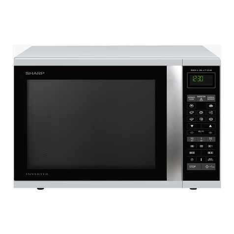
For Sharp Built-in Kit Models RK-94S27 or RK-94S30
THIS KIT IS UL APPROVED TO ALLOW CERTAIN MICROWAVE OVENS TO BE INSTALLED
ABOVE ANY ELECTRIC WALL OVEN. PLEASE SEE THE OPERATION MANUAL
REGARDING APPROVED BUILT-IN APPLICATIONS.
IMPORTANT:
This Built-in Kit is designed for and approved only for those Sharp
Microwave Ovens specifying Built-In Kit RK-94S27 or RK-94S30.
Refer to operation manual for approved models or www.sharpusa.
com\trimkits
PLEASE READ THESE INSTRUCTIONS
THOROUGHLY BEFORE
BEGINNING INSTALLATION!
• Always DISCONNECT THE PLUG of the microwave oven from the
electrical outlet before installing the Built-in Kit. Remove the Carou-
sel turntable from the oven cavity.
• Because the kit includes metal parts, due caution should be used
in handling and installation to avoid the possibility of injury.
INSTALLATION INSTRUCTIONS
ITEM PART NAME QTY
A DUCT (A)-1
PDUC-0259WRW0 1
B DUCT (A)-2
PDUC-B127MRP0 1
C DUCT (A)-3
PDUC-A734WRW0 1
D DUCT (B)
PDUC-0260WRW0 1
E DUCT (C)
PDUC-A274WRW0 1
F BOTTOM DUCT ASSEMBLY
FDUC-B099MRK1A 1
G M3.9-16MM PAN HEAD TAPPING
SCREW, ZINC
XOPS740P16000
4
H WOOD SCREW
XTSS740P20000 2
I CABINET SCREW/ CLEAR
XOTS740P12000 10
J FRONT FRAME
RK-94S27: FDECAB229MRK0
RK-94S30: FDECAB227MRK0
1
K BACK FRAME
RK-94S27: FDECAB230MRK0
RK-94S30: FDECAB226MRK0
1
L CUSHION SHEET
PCUSGB059MRP0 1
Check list for parts when unpacking. Note J. Front
Frame and K. Back Frame are shipped attached.
Snap apart before installation.
A
F
G
H
I
J
K
L
B
C
D
E
DUCT (A)-1
DUCT (A)-2
DUCT (A)-3
DUCT (B)
DUCT (C)
2
E
Provide an opening in the wall or cabinet as indicated in
Figure 1. The depth should be a minimum of 20-1/8". If the
Depth (E) dimension is greater than 21", the outlet location
may be in any area on the rear wall. The oor of the opening
should be constructed of plywood strong enough to support
the weight of the oven (approximately 100 lbs.) and should
be level for proper operation of the oven.
NOTE: While the proper function of the oven does not
require that the opening be enclosed (with sides, ceiling
and rear partition), this may be required by local code, and
it is suggested that the local code be checked for any such
requirement.
The opening in the wall or cabinet must be within the
following dimensions, centered horizontal to the cabinet.
RK-94S27 RK-94S30
A20" 20"
B26-7/8" 29-7/8"
C18-1/2" 18-1/2"
D 25-1/4" 25-1/4"
EMin. 20-1/8" Min. 20-1/8"
F5" 5"
G10" 10"
A. Insert the edge of DUCT (B) into the hold lip of DUCT (C).
Secure together by using a SCREW (I) provided in the kit.
See Figure 2.
DUCT (C)
DUCT (B)
SCREW (I)
Figure 2
B. Position DUCT (A)-1 on the top of the oven inserting
edge of DUCT (BC) assembly into hole lip of DUCT (A)-1.
Tighten two SCREWS (I), securing DUCT (A)-1 to DUCT
(BC) assembly. See Figure 3.
SCREW (I) DUCT (A)-1
DUCT (BC) SCREW (I)
Figure 3
Outlet should NOT be in the shaded area as indicated on
Figure 1.
NOTE
• If the dimension of DEPTH (E) is more than 21", the outlet
location may be any area on the rear wall.
D
C
34-1/2” MIN.
FLOOR
FLOOR
A
B
G
F
E
STEP 1 CABINET OR WALL OPENING
STEP 2 EXHAUST DUCT ASSEMBLY
C. Position DUCT (A)-2 on the top of the oven and insert it
into the hold lip of DUCT (A)-1. Secure DUCT (A)-2 to DUCT
(A)-1 using two SCREWS (I) provided. See Figure 4.
SCREW (I)
SCREW (I)
DUCT (A)-2
DUCT (A)-1
D. Position DUCT (A)-3 on top of the oven and insert it into
DUCT (A)-2. Secure DUCT (A)-3 using three SCREWS (I)
provided. See Figure 5.
SCREW (I)
SCREW (I)
SCREW (I)
DUCT (A)-3
DUCT (A)-2
NOTE: Floor of opening
should be 90˚ to front
cabinet frame.
Figure 1
Figure 4
Figure 5
E
3
STEP 3 SURFACE INSTALLATION
E. Carefully turn over exhaust assembly. Remove adhesive
backing from CUSHION L. The cushion should be applied
to the anges of the duct assembly as indicated by
arrows. See Figure 5A.
CUSHION L
Figure 5A
F. Remove SCREW from the upper right and left corners at
the rear of the oven. Place duct assembly on the top of
the unit as shown and secure the duct assembly to the
oven using the two screws just removed from the oven.
See Figure 5B.
SCREW
SCREW
Figure 5B
A. BOTTOM DUCT ASSEMBLY: Place the Bottom duct in the
center of the opening so that gap "A" is equal to gap "B".
When the Bottom Duct assembly is positioned properly,
the front edge of the duct will be ush with the front of the
cabinet. Secure with 2 SCREWS (H) See Figure 6.
GAP "A"
NOTE:
CENTER BOTTOM
DUCT ASSEMBLY IN
THE OPENING
DETAIL A GAP "B"
BOTTOM DUCT ASSEMBLY
SCREW (H)
Figure 6
B. CABINET INSTALLATION: Place the oven adjacent to
the wall or cabinet opening. Plug the power cord into the
electrical outlet. Carefully guide the assembled oven into
the prepared opening. Slide the oven on the Bottom Duct
assembly. See Figure 7.
Figure 7
4
E
For any other assistance or information about this kit,
in USA please call Sharp’s Customer Assistance Center at
1-800-BE-SHARP (1-800-237-4277)
In Canada, call 905-568-7140
SHARP ELECTRONICS CORPORATION
1 Sharp Plaza Suite 1, Mahwah, New Jersey 07495-1123, U.S.A.
SHARP ELECTRONICS OF CANADA LTD.
335 Britannia Road East Mississauga, Ontario L4Z 1W9, Canada
C. CABINET INSTALLATION: Avoid pinching the cord
between the oven and the wall. Adjust the position of the
oven so that the feet of the oven are tted into the holes
of the Bottom Duct Assembly. See Figure 8.
DUCT RECESS
BOTTOM
DUCT
ASSEMBLY
FOOT
Figure 8
D. BACK FRAME INSTALLATION: Position back frame equal
space top to bottom, side to side. Mark for 4 holes, center
punch and pre-drill with 1/16" drill bit. Secure frame with 4
SCREWS (G). See Figure 9.
EQUAL GAP TOP, BOTTOM
EQUAL GAP
SIDE TO SIDE
MOUNTING HOLES
MOUNTING HOLES
MOUNTING HOLES
MOUNTING HOLES
Figure 9
E. FRONT FRAME INSTALLATION: Place the FRONT FRAME
onto the BACK FRAME and align ball studs and receivers.
Secure the FRONT FRAME to the BACK FRAME by rmly
pushing the front frame onto the back frame engaging the
four (4) snap attachments. See Figure 10.
SNAP
ATTACHMENT
Figure 10