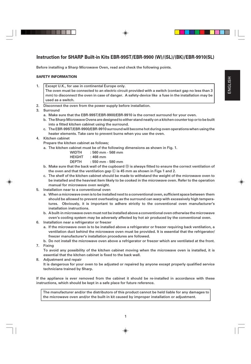
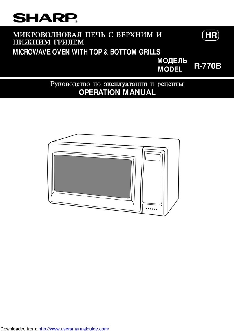
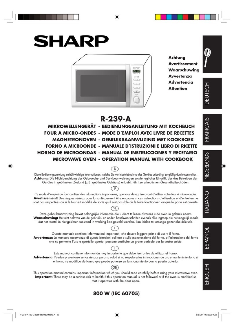
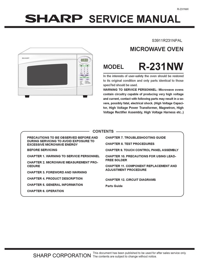
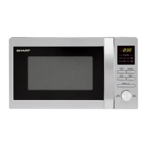
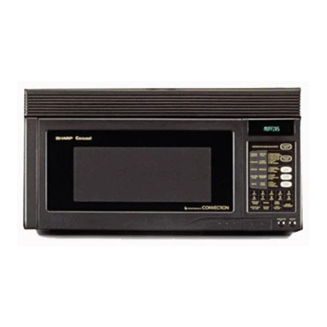
Sharp R-8000G User manual

R-8000G
In the interest of user-safety the oven should be restored to its original
condition and only parts identical to those specified should be used.
WARNING TO SERVICE PERSONNEL: Microwave ovens contain
circuitry capable of producing very high voltage and current, contact
with following parts may result in a severe, possibly fatal, electrical
shock. (High Voltage Capacitor, High Voltage Power Transformer,
Magnetron, High Voltage Rectifier Assembly, High Voltage Harness
etc..)
TABLE OF CONTENTS
COMMERCIAL
HIGH SPEED CONVECTION
MICROWAVE OVEN
Page
PRECAUTIONS TO BE OBSERVED BEFORE AND DURING SERVICE TO
AVOID POSSIBLE EXPOSURE TO EXCESSIVE MICROWAVE ENERGY............................ INSIDE FRONT COVER
BEFORE SERVICING ............................................................................................................... INSIDE FRONT COVER
WARNING TO SERVICE PERSONNEL ........................................................................................................................ 1
MICROWAVE MEASUREMENT PROCEDURE ............................................................................................................ 2
FOREWORD AND WARNING ....................................................................................................................................... 3
PRODUCT SPECIFICATIONS ....................................................................................................................................... 4
GENERAL INFORMATION ........................................................................................................................................... 4
OPERATION ................................................................................................................................................................... 6
TROUBLESHOOTING GUIDE ..................................................................................................................................... 13
TEST PROCEDURE ..................................................................................................................................................... 15
TOUCH CONTROL PANEL .......................................................................................................................................... 25
PRECAUTIONS FOR USING LEAD-FREE SOLDER .................................................................................................. 29
PROCEDURE FOR CHECKING/ SETTING TOTAL OPERATION TIME .................................................................... 30
COMPONENT REPLACEMENT AND ADJUSTMENT PROCEDURE ......................................................................... 31
SERVICE MAINTENANCE CLEANING ....................................................................................................................... 39
PICTORIAL DIAGRAM ................................................................................................................................................. 40
POWER UNIT, CPU UNIT AND CONTROL UNIT CIRCUIT ........................................................................................ 41
GRID ASSIGNMENT OF FLUORESENT DISPLAY TUBE .......................................................................................... 42
PRINTED WIRING BOARD .......................................................................................................................................... 42
PARTS LIST ................................................................................................................................................................. 44
PACKING AND ACCESSORIES .................................................................................................................................. 47
R-8000G
SY313R8000GP/
MODEL
SERVICE MANUAL
SHARP CORPORATION
This document has been published to be used for after
sales service only.
The contents are subject to change without notice.

R-8000G
48
6
4 5
123
6
4 5
123
A
B
C
D
E
F
G
H
A
B
C
D
E
F
G
H
OVEN AND CABINET PARTS
7-8
6-14
2-4
4-1
4-56
4-36
4-59
7-12
1-8 1-25
4-60
7-10
4-60
4-68
4-40
1-11
7-7
7-7 7-1
7-6
7-7
4-47
7-4
7-4
7-10
1-10
4-15 4-77
1-17
1-14
7-17
1-19
7-9
4-81
7-7
7-8
4-72 6-19
6-6
4-45
2-1
x3
7-23
4-78
7-22
7-23
1-18
7-9
4-25
4-63
7-9
7-9
7-2
7-12
7-17
4-26
1-16
4-64
7-2
7-2
7-2
7-2
4-21
x2
x4
7-2x2
x4
7-2
1-5
x4
x2
7-17
7-2
7-20
6-12
7-9
7-9
4-75
7-2
4-79
4-37
4-13
4-30
7-12 4-55
7-2
7-19
4-12
7-2
7-2
7-7
7-16
1-4
7-16 7-16
4-35
4-52
7-2
4-69
1-13
1-13
6-13
1-21 x2
7-13 4-32
4-10
7-13
7-7
4-39
4-59
x2
x4
6-4
7-14
4-70
4-7
4-11
6-3
7-4 7-7
4-38
7-8
2-3
2-3
4-29
2-2
7-12
7-8
7-13
7-7
7-17
1-15
4-64
7-7
4-47
7-21
4-73
4-7
2-5
4-41
4-29
4-51
4-51
4-49
4-46
7-2 x3
7-4
4-80
7-13 7-4
4-53
7-5
7-12
4-23
7-11
4-48
4-74
1-2
1-12
7-2
7-10
4-16
7-2
7-2
7-2
1-3
4-9
7-14
7-2 4-22
1-22
1-24
4-42
4-50
7-21
7-12
7-10
7-7
4-54
7-8
7-7
7-8
7-12
4-33
4-34
4-67
7-4
4-5
4-76
7-19
4-24
6-15
7-4
1-7
4-14
7-1
x2
x4
7-12
4-83
4-83
4-80 4-28
4-31
1-8
7-13
7-5
7-15
4-2
3-1
7-18
x3
x3
7-8
6-11 1-9
7-9
7-7
7-7
4-71
7-7
7-3
1-6
6-17
7-9
4-58
4-3
4-82
4-80
4-19
4-18
7-3
4-20
4-66
1-23
4-27 4-65
4-57
4-17
7-8
1-20
4-62
4-61
1-1
4-4
4-6
4-43
1-12
1-1
4-8
4-44

49
R-8000G
6
4 5
123
6
4 5
123
A
B
C
D
E
F
G
H
A
B
C
D
E
F
G
H
3-4-1
3-4-2
3-9
3-6
3-7
3-10
3-10
3-10
3-8
3-3
3-4
3-10
3-2
3-4-3
x7
3-10 x7
3-10
x11
Actual wire harness may be different than illustration.
POSITION OF PURSE LOCK
6-18 Purse lock LL
6-18 Purse lock LL
Main wire harness
Main wire
harness
Touch control
transformer
Harness
assembly
Power unit
3-5
3-4-4
3-4-4
1-23
5-2
5-8 5-9
5-7
5-15
5-5
5-10
5-20 x2
x10
5-10
5-11
5-1
5-20
5-14
5-23
5-19 5-13
5-20
5-20
5-21 5-6
5-21
5-21
5-12
5-18
5-23
5-22
5-17
5-20
5-24
5-16
x2
5-21
5
6-1
6-16
6-18
6-2
6-9
6-10
5-14
5-22
5-17
5-4
5-3
MISCELLANEOUS
CONTROL PANEL PARTS
DOOR PARTS

R-8000G
44
PARTS LIST
*
*
*
*
∆*
Note: The parts marked "∆" may cause undue microwave exposure.
The parts marked "*" are used in voltage more than 250V.
REF. NO. PART NO. DESCRIPTION Q'TY CODE
ELECTRICAL PARTS
1- 1 QSW-MA085WRE0 Secondary interlock/3rd. Latch/door sensing switches 3 AF
1- 2 FPWBFA370WRKZ Noise filter 1 AZ
1- 3 RHET-A282WRZZ Top heating element 1 BB
1- 4 RHET-A281WRZZ Side heating element 1 BB
1- 5 FH-HZA053WRE0 Thermistor 1 AM
1- 6 RMOTCA015WRZZ Jet motor 1 BR
1- 7 RMOTDA255WRZZ Turntable motor 1 AW
1- 7 RMOTDA189WRE0 Turntable motor (Interchangeable) 1 AT
1- 8 FMOTEA474WRKZ Fan motor assembly 2 BE
1- 9 FACCDA104WREZ Power supply cord 1 BD
1-10 FH-DZA104WRKZ High voltage rectifier assembly 1 AN
1-11 RC-QZA288WRZZ High voltage capacitor (Interchangeable) 1 AW
1-11 RC-QZA235WRE0 High voltage capacitor 1 AU
1-12 FFS-BA033WRKZ Monitor fuse 20A and monitor switch (V-5220Q) assembly 1 AM
1-13 VHRG3NE22TL-1 Solid-state relay 2 AY
1-14 QFS-CA026WRZZ Fuse F10A 1 AH
1-15 QFS-TA014WRE0 Temperature fuse 150 deg. C (MG) 1 AG
1-16 QSOCLA021WRE0 Oven lamp socket 1 AG
1-17 QFSHDA019WRE0 Fuse holder 1 AH
1-18 RC-QZA311WREZ Jet motor capacitor 1 AQ
1-19 RLMPTA089WRZZ Oven lamp 1 AM
1-20 RTHM-A109WRE0
Thermal cut out 170 deg.C(Top heater) 170deg.C OFF 155deg.C ON
1 AM
1-20 RTHM-A048WRE0
Thermal cut out 170 deg.C " " (Interchangeable)
1 AH
1-21 RTHM-A110WRE0
Thermal cut out 150 deg.C(Side heater) 150deg.C OFF 130deg.C ON
1 AK
1-22 RTRN-A716WRZZ Power transformer 1 BS
1-23 RTRNPA003WRZZ Touch control transformer 1 AY
1-24 RV-MZA294WRE0 Magnetron 1 BL
1-25 QTANDA001WRZZ Terminal board 1 AE
CABINET PARTS
2- 1 GCABDA104WRPZ Back plate 1 AZ
2- 2 GDAI-A356WRWZ Bottom plate 1 AW
2- 3 GLEGPA096WREZ Front leg 2 AD
2- 4 GCABUA906WRPZ Outer case cabinet 1 BH
2- 5 GCOVHA449WRWZ Turntable motor cover 1 AP
CONTROL PANEL PARTS
3- 1 DPWBFC375WRKZ Power unit 1 BK
3- 2 DPWBFC374WRKZ CPU unit 1 BT
3- 3 DPWBFC377WRKZ Control unit (switch unit) 1 BK
3- 4 FPNLCB769WRKZ Panel sub assembly 1 BD
3- 4-1 HDECAA231WRPZ Sus decoration 1 AU
3- 4-2 HDECQA228WRTZ Panel decoration 1 AN
3- 4-3 XEBSD30P08000 Special screw 7 AA
3- 4-4 PCUSGA641WRPZ Cushion 2 AG
3- 5 FW-VZB993WREZ Harness assembly 1 AT
3- 6 GMADIA115WRFZ Display window 1 AD
3- 7 LANGKB018WRPZ Panel angle 1 AV
3- 8 PCUSGA583WREZ Cushion 1 AH
3- 9 PSHEPA960WREZ Key sheet 1 AY
3-10 XEPSD30P10000 Screw; 3mm x 10mm 22 AA
OVEN PARTS
4- 1 DFTA-A017WRYZ Damper duct assembly 1 AZ
4- 2 PZETEA084WRFZ PWB mounting angle 1 AL
4- 3 PCUSGA600WREZ Cushion 1 AF
4- 4 MLEVPA248WRFZ Switch lever right A 1 AH
4- 5 MLEVPA249WRFZ Switch lever right B 1 AH
4- 6 MSPRCA146WREZ Spring 1 AE
4- 7 MSPRTA222WREZ Spring 2 AE
4- 8 MLEVPA250WRFZ Switch lever left A 1 AH
4- 9 LANGFA242WRPZ Heater mounting angle A 1 AS
4-10 PDUC-A821WRTZ Heater duct upper 1 BF
4-11 MLEVPA251WRFZ Switch lever left B 1 AH
4-12 LANGFA260WRPZ Heater mounting angle B 1 AS
4-13 PDUC-A822WRTZ Heater duct left 1 BF
4-14 FANGTA167WRKZ Coupling assembly 1 AK

R-8000G
45
∆
∆
∆
∆
∆
REF. NO. PART NO. DESCRIPTION Q'TY CODE
4-15 FDUC-A381WRWZ Exhaust duct 1 AZ
4-16 FFANMA016WRKZ Convection fan assembly 1 AZ
4-17 LANGFA243WRPZ Convection motor mounting angle 1 AS
4-18 PDUC-A825WRPZ Convection duct 1 AW
4-19 PFPF-A229WREZ Thermal insulator back 1 AP
4-20 PREFHA072WRWZ Thermal cover back 1 AV
4-21 PSKR-A388WRWZ Divide plate A 1 AS
4-22 PSKR-A389WRWZ Divide plate B 1 AS
4-23 ************* Oven cavity (Not replaceable part) 1 --
4-24 LANG-A095WRPZ Turntable mounting angle 1 AN
4-25 LANGQA569WRPZ Separator left 1 AS
4-26 LANGQA596WRWZ Light mounting plate 1 AS
4-27 PSKR-A387WRPZ Magnetron separator 1 AS
4-28 PCUSGA601WREZ Cushion 1 AC
4-29 PCUSGA603WREZ Cushion 2 AD
4-30 PFPF-A236WRPZ Thermal insulation left 1 AX
4-31 PSKR-A400WRFZ Rear separator 1 AS
4-32 PFPF-A237WRPZ Thermal insulation Upper 1 AX
4-33 PFPF-A228WRPZ Thermal insulation Bottom 1 AQ
4-34 PGLSPA597WRZZ Lamp glass 1 AF
4-35 PPACGA189WREZ Silicon packing 1 AE
4-36 PREFHA077WRPZ Thermal cover Upper 1 AV
4-37 PREFHA078WRWZ Thermal cover Left 1 AV
4-38 PREFHA071WRPZ Thermal cover D 1 AV
4-39 LANGQA572WRPZ Fan motor mounting angle 1 AS
4-40 LBNDKA158WRPZ Capacitor holder 1 AF
4-41 FHNG-A316WRYZ Oven hinge Left 1 AU
4-42 FHNG-A317WRYZ Oven hinge Right 1 AU
4-43 PHOK-A134WRFZ Latch hook Right 1 AL
4-44 PHOK-A135WRFZ Latch hook Left 1 AL
4-45 GCOVHA460WRPZ Louver cover 1 AS
4-46 LANG-A096WRPZ Transformer mounting angle 1 AN
4-47 LANGFA241WRWZ Chassis support 2 AS
4-48 LANGKB019WRWZ Magnetron guide 1 AV
4-49 MCAMPA115WRMZ Door cam Left 1 AP
4-50 MCAMPA116WRMZ Door cam Right 1 AP
4-51 MSPRTA219WREZ Door spring 2 AE
4-52 PCOVPA402WREZ Waveguide cover 1 AK
4-53 PCUSGA602WREZ Cushion 1 AG
4-54 GCOVHA446WREZ Screw cap 1 AC
4-55 PCUSGA584WREZ Cushion 2 AB
4-56 PCUSUA589WREZ Cushion 1 AC
4-57 PCUSGA585WREZ Cushion 1 AB
4-58 PCUSUA591WREZ Cushion 1 AD
4-59 PCUSUA592WREZ Cushion 2 AC
4-60 PCOVPA389WREZ Edge cover 2 AC
4-61 PCUSUA614WREZ Cushion 1 AB
4-62 PCUSUA609WREZ Cushion 1 AD
4-63 PCUSUA610WREZ Cushion 1 AE
4-64 PCUSUA611WREZ Cushion 3 AB
4-65 PCUSUA612WREZ Cushion 1 AC
4-66 PCUSUA502WRP0 Cushion 1 AD
4-67 LANGKB074WRPZ Glass mounting plate 1 AV
4-68 PCUSGA637WRPZ Cushion 1 AG
4-69 MSPRCA147WREZ Spring 1 AE
4-70 MSPRTA220WREZ Spring 1 AD
4-71 GCOVHA461WRPZ Exhaust cover 1 AS
4-72 GCOVHA462WRPZ Lamp cover 1 AS
4-73 GCOVHA466WRWZ Steam cover 1 AP
4-74 LANGQA581WRPZ Noise filter angle 1 AS
4-75 LANGQA595WRPZ Radiation plate 1 AS
4-76 PCUSGA586WREZ Cushion 1 AC
4-77 PCUSGA607WREZ Cushion 1 AF
4-78 PCUSGA626WRPZ Cushion 1 AG
4-79 PCUSGA627WRPZ Cushion 1 AG
4-80 PCUSUA237WRP0 Cushion 3 AF
4-81 PCUSUA424WRP0 Cushion 1 AG
4-82 PCUSUA616WREZ Cushion 1 AE
4-83 PPACGA218WRPZ Cushion 2 AG
DOOR PARTS
5 CDORFA994WRKZ Door assembly 1 BZ
5- 1 DDORFB092WRYZ Door panel assembly 1 BR
5- 2 JHNDPA225WREZ Door handle 1 BF
∆
∆
R-8000G
46
REF. NO. PART NO. DESCRIPTION Q'TY CODE
∆
∆
∆
∆
5- 3 LHLD-A258WRFZ Handle holder R 1 AR
5- 4 LHLD-A259WRFZ Handle holder L 1 AR
5- 5 PCUSGA588WRPZ Cushion 2 AH
5- 6 GCOVHA439WRFZ Choke cover 1 AR
5- 7 GWAKPA924WRFZ Door frame 1 BD
5- 8 HDECAA230WRPZ Stainless cover 1 AY
5- 9 HDECQA227WRTZ Door decoration 1 AT
5-10 LANGKA989WRPZ Glass mounting angle A 2 AG
5-11 LANGKA990WRPZ Glass mounting angle B 1 AQ
5-12 LSTPPA224WREZ Latch head Right 1 AH
5-13 LSTPPA225WREZ Latch head Left 1 AH
5-14 MSPRCA149WREZ Handle spring 2 AE
5-15 PGLSPA577WREZ Front door glass 1 AX
5-16 PGLSPA578WREZ Middle door glass 1 AU
5-17 MLEVFA089WRWZ Handle lever 2 AM
5-18 MSPRCA137WREZ Latch spring Right 1 AC
5-19 MSPRCA138WREZ Latch spring Left 1 AC
5-20 XEPSD40P08000 Screw : 4mm x 8mm 16 AB
5-21 XEPSD40P20000 Screw : 4mm x 20mm 6 AB
5-22 LPIN-A179WREZ Handle pin 2 AG
5-23 LX-BZ0139WRE0 Special screw 2 AA
5-24 PPACGA224WRPZ Cushion 2
MISCELLANEOUS
6- 1 FAMI-A120WRYZ High rack assembly 1 AX
6- 2 FAMI-A121WRYZ Low rack assembly 1 AX
6- 3 FROLPA105WRYZ Turntable support 1 AX
6- 4 NTNT-A113WRHZ Turntable tray 1 AU
6- 5 TLABMA942WRRZ Menu label 1 AL
6- 6 TMAPCA769WRRZ Schematic diagram 1 AL
6- 7 TINSEB012WRRZ Instruction book 1 AP
6- 8 TLABNA964WRRZ Recipe sheet 1 AL
6- 9 FW-VZB994WREZ Main wire harness 1 BK
6-10 FW-VZB995WREZ Thermistor harness 1 AU
6-11 LBSHCA012WRE0 Cord bushing 1 AD
6-12 LHLDWA060WREZ Wire holder 1 AF
6-13 TCAUAA285WRRZ Monitor caution 1 AF
6-14 TCAUAA166WRR0 DHHS caution label 1 AB
6-15 TCAUAA276WRRZ User caution label 1 AH
6-16 PZET-A011WRE0 Thermal insulator 1 AA
6-17 LHLDWA029WRE0 Cord holder 1 AB
6-18 LHLDWA013WRE0 Purse lock LL 2 AC
6-19 TCAUAA286WRRZ Lamp caution 1 AH
6-20 TCAUZA005WRRZ Caution sheet 1 AF
SCREWS NUTS AND WASHERS
7- 1 XNEUW40-32000 Nut: 4mm x 3.2mm 4 AA
7- 2 XOTWW40P08000 Screw : 4 mm x 8 mm 51 AB
7- 3 XBTSD40P06000 Screw : 4 mm x 6 mm 6 AA
7- 4 XHPSD40P08K00 Screw : 4 mm x 8 mm 7 AC
7- 5 XHTSD40P08RV0 Screw : 4mm x 8mm 2 AA
7- 6 XWSUW40-10000 Washer : 4mm x 1.0mm 2 AA
7- 7 XOTSD40P08000 Screw : 4mm x 8mm 23 AA
7- 8 XOTSD40P12000 Screw : 4mm x 12mm 14 AA
7- 9 LX-BZA148WREZ Special screw 11 AC
7-10 LX-BZA149WREZ Special screw 8 AE
7-11 LX-EZA060WREZ Special screw 4 AC
7-12 XOTSD40P10000 screw : 4mm x 10mm 16 AA
7-13 XHTSD40P08000 Screw : 4mm x 8mm 7 AA
7-14 LX-BZA144WREZ Special screw 4 AB
7-15 XOTSD40P12RV0 Screw : 4mm x 12mm 4 AA
7-16 LX-BZA143WREZ Special screw 11 AB
7-17 LX-BZA146WREZ Special screw 7 AC
7-18 XEPSD30P10000 Screw : 3 mm x 10 mm 3 AA
7-19 LX-CZ0052WRE0 Special screw 2 AA
7-20 LX-BZA147WREZ Special screw 4 AC
7-21 XHPSD40P12KS0 Screw : 4mm x 12mm 4 AE
7-22 XONSC40P10000 Screw : 4mm x 10mm 1 AA
7-23 XOTSE40P08000 Screw : 4mm x 8mm 4 AA

R-8000G
47
HOW TO ORDER REPLACEMENT PARTS
To have your order filled promptly and correctly, please furnish the following information.
1. MODEL NUMBER 3. PART NO.
2. REF. NO. 4. DESCRIPTION
Order Parts from the authrized SHARP parts Distributor for your area.
Defective parts required return should be returned as indicated in the Service Policy.
PACKING AND ACCESSORIES
6-4 TURNTABLE TRAY
6-7 INSTRUCTION BOOK
6-5 MANU LABEL
6-8 RECIPE SHEET
6-3 TURNTABLE SUPPORT
DOOR PROTECTION SHEET
SPADPA620WREZ
MICROWAVE
OVEN
TOP PAD ASSEMBLY
FPADBA549WRKZ
PLASTIC BAG
SSAKHA075WREZ
TRAY PROTECT
(SPADPA629WREZ)
6-1 HIGH RACK
6-2 LOW RACK
BOTTOM PAD ASSEMBLY
FPADBA550WRKZ
Not replaceable items.
PACKING CASE
SPAKCD991WREZ
TRAY PAD
SPADPA621WREZ
TRAY HOLDER
SPADFA530WREZ
CAUTION SHEET
TCAUZA005WRRZ
Other manuals for R-8000G
2
Table of contents
Other Sharp Microwave Oven manuals

Sharp
Sharp YC-QS204AU User manual

Sharp
Sharp R-28ST User manual

Sharp
Sharp R-342H User manual

Sharp
Sharp R-203EW User manual

Sharp
Sharp R-3A56(W) User manual

Sharp
Sharp R-420EK User manual

Sharp
Sharp Carousel R-1511 User manual

Sharp
Sharp R-9360 User manual

Sharp
Sharp R-750D User manual

Sharp
Sharp Twin Touch R-CD2200M User manual

Sharp
Sharp EBR-4900 AL User manual

Sharp
Sharp R-520KS User manual

Sharp
Sharp Carousel R-480J User manual

Sharp
Sharp R-209B User manual

Sharp
Sharp R-THY11 User manual

Sharp
Sharp R-798 Instruction Manual

Sharp
Sharp R-971(IN)W User manual

Sharp
Sharp R642BKW User manual

Sharp
Sharp Carousel R-890N User manual

Sharp
Sharp R-300BW User manual