Sharp R-9H58 User manual

R-9H58
TABLE OF CONTENTS
Page
CAUTION, MICROWAVE RADIATION ............................................................................................................. 1
WARNING...........................................................................................................................................................1
PRODUCT SPECIFICATIONS.......................................................................................................................... 2
GENERAL INFORMATION ................................................................................................................................ 2
APPEARANCE VIEW........................................................................................................................................ 3
OPERATION SEQUENCE ................................................................................................................................ 4
FUNCTION OF IMPORTANT COMPONENTS ................................................................................................. 7
SERVICING ..................................................................................................................................................... 10
TEST PROCEDURE ........................................................................................................................................ 12
TOUCH CONTROL PANEL ............................................................................................................................. 20
COMPONENT REPLACEMENT AND ADJUSTMENT PROCEDURE............................................................ 26
MICROWAVE MEASUREMENT ..................................................................................................................... 31
WIRING DIAGRAM ......................................................................................................................................... 32
PICTORIAL DIAGRAM.................................................................................................................................... 34
CONTROL PANEL CIRCUIT ........................................................................................................................... 35
PRINTED WIRING BOARD ............................................................................................................................. 36
PARTS LIST..................................................................................................................................................... 37
S8606R9H58PJ/
CONVECTION
MICROWAVE OVEN
MODEL R-9H58
In interests of user-safety the oven should be restored to its original
condition and only parts identical to those specified should be used.
SERVICE MANUAL
SHARP CORPORATION

R-9H58

R-9H58
1
SERVICE MANUAL
CONVECTION
MICROWAVE OVEN
R-9H58
GENERAL IMPORTANT INFORMATION
ThisManualhasbeenpreparedtoprovideSharpCorp.Service
engineers with Operation and Service Information.
It is recommended that service engineers carefully study the
entire text of this manual, so they will be qualified to render
satisfactory customer service.
CAUTION
MICROWAVE RADIATION
DONOTBECOMEEXPOSEDTORADIATIONFROMTHE
MICROWAVE GENERATOR OR OTHER PARTS
CONDUCTING MICROWAVE ENERGY.
Service engineers should not be exposed to the microwave
energy which may radiate from the magnetron or other
microwave generating devices if it is improperly used or
connected. All input and output microwave connections,
waveguides, flanges and gaskets must be secured. Never
operate the device without a microwave energy absorbing
load attached. Never look into an open waveguide or an-
tenna while the device is energized.
WARNING
Never operate the oven until the following points are ensured.
(A) The door is tightly closed.
(B) The door brackets and hinges are not defective.
(C) The door packing is not damaged.
(D) The door is not deformed or warped.
(E) There is not any other visible damage with the oven.
Servicing and repair work must be carried out only by trained
service engineers.
All the parts marked "*" on parts list are used at voltages more
than 250V.
Removal of the outer wrap gives access to potentials above
250V.
All the parts marked "∆" on parts list may cause undue micro-
wave exposure, by themselves, or when they are damaged,
loosened or removed.
SHARP CORPORATION
OSAKA, JAPAN
PRODUCT SPECIFICATIONS
APPEARANCE VIEW
OPERATING SEQUENCE
FUNCTION OF IMPORTANT
COMPONENTS
SERVICING AND
TROUBLESHOOTING CHART
TEST PROCEDURE
TOUCH CONTROL PANEL
ASSEMBLY
COMPONENT REPLACEMENT
AND ADJUSTMENT PROCEDURE
MICROWAVE MEASUREMENT
WIRING DIAGRAM
PARTS LIST

R-9H58
2
PRODUCT SPECIFICATIONS
ITEM DESCRIPTION
Power Requirements 230 - 240 Volts
50 Hertz
Single phase, 3 wire earthed
Power Consumption 1500 W (Microwave)
1600 W (Convection)
Power Output 850 watts (IEC-705-1988 )
Operating frequency of 2450MHz
Convection heater 1500 W
Case Dimensions Width 627mm
Height 378mm
Depth 483mm
Cooking Cavity Dimensions Width 410mm
Height 245mm
Depth 410mm
Control Complement Touch Control System
Clock ( 1:00 - 12:59)
Timer (0 - 99 min. 99 sec.)
Microwave Power for Variable Cooking
Repetition Rate;
HIGH................................................. Full power throughout the cooking time
MED HIGH........................................................... approx. 70% of Full Power
MED...................................................................... approx. 50% of Full Power
MED LOW (DEFROST) ........................................approx. 30% of Full Power
LOW ..................................................................... approx. 10% of Full Power
Convection Temperature for Variable Cooking
CONVECTION...................................................... 40 to 250˚C Temp. control
LOW MIX(BAKE) ..................................180˚C with 10% of microwave power
HIGH MIX(ROAST)...............................200˚C with 30% of microwave power
GRILL ................................................................................... 250˚C (Preheat)
HELP pad
SENSOR INSTANT ACTION pads
MULTI COOK pad
REHEAT SENSOR pad
CONVECTION COOKING FUNCTION pads
EASY DEFROST pad
NUMBER and TEMPERATURE pads
POWER LEVEL pad
MEMORY pad
MORE. LESS pads
STOP/CLEAR pad
CLOCK pad
INSTANT COOK/START pad
Set Weight Approx. 29 kg
GENERAL INFORMATION
WARNING
THIS APPLIANCE MUST BE EARTHED
IMPORTANT
THE WIRES IN THIS MAINS LEAD ARE COLOURED IN ACCORDANCE WITH THE FOLLOWING CODE:
GREEN-AND-YELLOW : EARTH
BLUE : NEUTRAL
BROWN : LIVE

R-9H58
3
APPEARANCEVIEW
1. Ventilation opening
2. Oven lamp
3. Door hinges
4. Door safety latches
5. See through door
6. Door seal and sealing surfaces
7. Door open button
8. Touch control panel
9. Digital readout
10.Wave guide cover
11.Coupling
12.Access cover for oven lamp replacement
13.Menu label
14.Rating label
15. low rack
16.High rack TOUCH CONTROL PANEL
15 16
3
4
411
7
9
8
52
13
1
12
10
6
14
HELP
MULTI
COOK
REHEAT
SENSOR
SENSOR INSTANT ACTION
POWER
LEVEL EASY
DEFROST
STOP
CLEAR
CLOCK
LOW MIX HIGH MIX
GRILL
CONVEC
LESS MORE
MEMORY PREHEAT
Fresh
Vegetables
Frozen
Vegetables
Casseroles Desserts
Reheat
Pie Jacket
Potato
Info Display
1 2 3 4 5
6 7 8 9 O
I
NSTANT COOK
START
MULTI COOK PAD
Press to select Multi Cook
mode.
MORE ( ), LESS ( ) PADS
Press to increase/decrease the
time in one minute increments
during cooking or to alter the
doneness for the Sensor In-
stant Action, Reheat Sensor,
Multi Cook or Easy Defrost
modes.
CONVECTION COOKING
FUNCTION PADS
Press to cook for each func-
tion.
POWER LEVEL PAD
Press to select microwave
power setting.
If not pressed, HIGH is au-
tomatically selected.
NUMBER AND TEMPERATURE
PADS
Press to enter cooking times, clock
time, convection temperature or to
select the Multi Cook menus.
STOP/CLEAR PAD
Press to clear during program-
ming.
Press once to stop operation
of oven during cooking; press
twice to cancel cooking pro-
gram.
HELP PAD
Press to select auto start, in-
formation guide on/off, child
lock, demonstration modes or
info on pad.
Press to get cooking informa-
tion.
REHEAT SENSOR PAD
Press to select 3 popular Reheat
menu.
SENSOR INSTANT ACTION
PADS
Press once to cook or reheat 6
popular menus.
MEMORY PAD
Press to enter the frequently used
cooking program.
Press to recall the memorized pro-
gram.
EASY DEFROST PAD
Press to defrostmeat by enter-
ing weight only.
INSTANT COOK/START PAD
Press once to cook for 1 minute at
HIGH or increase by 1 minute
multiples each time this pad is
pressed during Microwave, Con-
vection, Grill or Mix cooking.
CLOCK PAD
Press to set Clock
Indicator
MIX CONV
DEFROST
SENSOR
COOK KG HELP
40˚C 70˚C 130˚C 150˚C 160˚C
180˚C 200˚C 220˚C 230˚C 250˚C

R-9H58
4
The following is a description of component functions
during oven operation.
Relay and Components Connection
RELAY CONNECTED COMPONENT
RY1 Oven lamp/ Turntable motor
RY2 Power transformer
RY3 Convection heater
RY4 Damper motor
RY5 Convection motor
RY6 Fan motor
OFF CONDITION
Closing the door activates all door interlock switches:
upper latch switch, lower latch switch and stop switch. (In
this condition, the monitor switch contacts are closed.)
When oven is plugged in a wall outlet (230 - 240V, 50Hz),
rated voltage is supplied to the control unit. (Figure O-1):
1. The display flashes “SHARP”, "MICRO-", "WAVE",
'OVEN".
To set any programmes or set the clock, you must first
touch the STOP/CLEAR pad.
“ : “ appears in the display and the time counts up
every minute.
NOTE: When the oven door is opened, the oven lamp
comes on at this time.
2. A signal is input to the control unit, energizing the coil
of shut-off relay (RY4).
RY4contactsclose,completingacircuittothedamper
motor. The damper motor mow operates moving the
damper to the open position, thereby closing the
contactsofdamperswitchinputsasignaltothecontrol
unit.
The coil of relay RY4 is de-energized, opening its
contacts, thereby turning off the damper motor.
MICROWAVE COOKING CONDITION
HIGH COOKING
Selectmicrowavecookingandpowerlevelbypressingthe
POWER LEVEL pad and then enter cooking time by
pressing the NUMBER pads. When the START pad is
touched, the following operations occur:
1. The contacts of relays are closed and components
connected to relays are turned on (RY1, RY2, RY6).
(Figure O-2)
2. Rated voltage is supplied to the primary winding of the
power transformer. The voltage is converted to about
3.35voltsA.C.outputonthefilamentwindingandhigh
voltage of approximately 2120 volts A.C. on the high
voltage winding.
3. The filament winding voltage (3.35 volts) heats the
magnetronfilamentandthehighvoltage(2120volts)is
sent to the voltage doubling circuit.
4 The 2450 MHz microwave energy produced in the
magnetron generates a wave length of 12.24 cm. This
energyischannelledthroughthewaveguide(transport
channel)into theoven cavity,where thefood isplaced
to be cooked.
5. Upon completion of the cooking time, the power
transformer, oven lamp, etc. are turned off and the
generation of microwave energy is stopped. The oven
will revert to the OFF condition..
6 When the door is opened during a cook cycle, the
monitor switch, upper latch switch, lower latch switch
andstopswitchareactivatedwiththefollowingresults.
The circuits to the turntable motor, cooling fan motor
and high voltage components are de-energized, the
ovenlampremainsonandthedigitalread-outdisplays
thetimestillremainingin the cookcyclewhenthe door
was opened.
7. The monitor switch is electrically monitoring the
operation of the upper latch switch and lower latch
switchandismechanicallyassociatedwiththedoorso
that it will function in the following sequence.
1) When the door opens from a closed potion, the upper
latch switch and the lower latch switch open their
contacts, and then the monitor switch contacts close.
2) When the door is closed, from the open position, the
monitorswitchcontactsfirstopen,andthenthecontacts
oftheupperlatchswitchandlowerlatchswitchmustbe
closed.
If the common and normal open contacts of upper latch
switch and the lower latch switch fail with their contacts
closedwhenthedoorisopened,theclosingofthemonitor
switch contacts will form a short circuit through the fuse,
upper latch switch and the lower latch switch, causing the
monitor fuse to blow.
MEDIUM HIGH, MEDIUM, MEDIUM LOW, LOW
COOKING
When variable cooking power is programmed, the rated
voltageis supplied tothe powertransformer intermittently
through the contacts of the relay (RY2) which is operated
by the control unit within a 32-second time base. Micro-
wave power operation is follows:
VARI MODE ON TIME OFF TIME
HIGH (100% power) 32 sec. 0 sec.
MED HIGH (approx. 70% power) 24 sec. 8 sec.
MED (approx. 50% power) 18 sec. 14sec.
MED LOW (approx. 30% power) 12 sec. 20 sec.
LOW (approx. 10% power) 6 sec. 26 sec.
NOTE: TheON/OFFtimeratiodoesnotexactlycorrespond
to the percentage of microwave power, because
approx. 2 seconds are needed for heating up the
magnetron filament.
CONVECTION COOKING CONDITION
PREHEATING CONDITION
Press the PREHEAT pad and then select preheating
temperature by pressing the temperature pad. When the
START pad is touched, the following operations occur:
1. The coil of shut-off relays RY1+RY5+RY6 are
energized,the ovenlamp, cooling fan motor, turntable
motor and convection motor are turned on.
2. The coil of relay (RY4) is energized by the CPU unit.
The damper is moved to the closed position, opening
thedamperswitchcontacts.Theopeningofthedamper
switch contacts sends a signal to the LSI on the CPU
OPERATION SEQUENCE

R-9H58
5
unit de-energizing the relay (RY4) and opening the
circuit to the damper motor.
3. Thecoil ofheater relay (RY3) is energizedby theCPU
unit and the main supply voltage is added to the
convection heater.
4. When the oven temperature reaches the selected
preheat temperature, the following operations occur:
4-1. The heater relay (RY3) is de-energized by the CPU
unit temperature circuit and thermistor, opening the
circuit to the convection heater.
4-2. The oven will continue to function for 30 minutes,
turning the convection heater on and off, as needed
to maintain the selected preheat temperature. The
oven will shut-down completely after 30 minutes.
CONVECTION COOKING CONDITION
When the preheat temperature is reached, a beep signal
will sound indicating that the holding temperature has
beenreachedintheovencavity.Openthedoorandplace
the food to be cooked in the oven. Press the CONVEC-
TION pad and then enter the cooking temperature by
pressingthetemperaturepad.Andthenenterthecooking
time by pressing the NUMBER pads. When the START
pad is touched, the following operations occur:
1. The numbers of the digital read-out start the count
down to zero.
2. Theovenlamp,turntablemotor, cooling fanmotorand
convection motor are energized.
3. Heaterrelay(RY3)isenergized(ifthecavitytemperature
is lower than the selected temperature) and the main
supply voltage is applied to the convection heater to
return to the selected cooking temperature.
4. Upon completion of the cooking time, the audible
signal will sound, and oven lamp, turntable motor,
cooling fan motor and convection motor are de-
energized. At the end of the convection cycle, if the
cavity air temperature is above 116˚C, the circuit to
(RY6) will be maintained (by the thermistor circuit) to
continue operation of the cooling fan motor until the
temperature drops below 116˚C, at which time the
relay will be de-energized, turning off the fan motor.
Relay (RY5) will however, open as soon as the
convectioncyclehasended,turningofftheconvection
fanmotor.Thiswillnowcoolandallowthedamperdoor
to open.
5. At the end of the convection cook cycle, shut-off relay
(RY4) is energized turning on the damper motor. The
damper is returned to the open position, closing the
damper switch contacts which send a signal to the
control unit, de-energizing shut-off relay (RY4).
AUTOMATIC MIX COOKING CONDITION
Choose the LOW MIX or HIGH MIX by pressing the LOW
MIXpadorHIGHMIXpad.Andthenentercookingtimeby
pressing the NUMBER pads. When the START pad is
touched, the following operations occur:
1. The numbers of the digital read-out start the count
down to zero.
2. Theshut-offrelay(RY1+RY5+RY6)energized,turning
on the oven lamp, turntable motor, cooling fan motor
and convection motor.
3. The shut-off relay (RY4) is energized.
The damper door is closed from the open position.
4. Theheater relay (RY3)is energized,adding themains
supply voltage to the convection heater.
5. Now, the oven is in the convection cooking condition.
6. When the oven temperature reaches the selected
temperature, the following operations occur:
6-1. The power supply voltage is added to the convection
heater and power transformer alternately.
6-2. The convection heater operates through the heater
relay (RY3) contacts and the power transformer
operates through the cook relay (RY2) contacts.
6-3. These are operated by the CPU unit to supply
alternately within a 48 second time base, convection
heat and microwave energy.
The relationship between the convection and microwave
power operations are as follows.
Note: The ON and OFF time ratio does not correspond
withthepercentageofmicrowavepower,because
approx. 2 seconds are needed for heating of the
magnetron filament.
16 SEC. 32 SEC.
48 SEC.
LOW MIX
BAKE
HIGH MIX
ROAST
MICROWAVE POWER
= APPROX. 30%
CONVECTION
TEMPERATURE
300˚F
MICROWAVE POWER
= APPROX. 10%
CONVECTION
TEMPERATURE
= 350˚F (180˚C)
40 SEC.8 SEC.
ON
ON
OFF
OFF
OFF
ON
(MICRO.)
(CONVEC.)
(MICRO.)
(CONVEC.)
Note: DuringalternateMicrowave/Convectionoperation,
the convection heater is energized only if the
cavity temperature drops below the set
temperature.
ABSOLUTE HUMIDITY SENSOR (AH SENSOR)
COOKING CONDITION
Incase where the AH sensor is used (REHEAT SENSOR
or SENSOR INSTANT ACTION), the foods are cooked in
microwave cooking mode without figuring time, power
level or quantity. When the oven senses enough steam
from the food, it relays the information to its microproces-
sor which will calculate the remaining cooking time and
power level needed for best results. When the food is
cooked, water vapour is developed. The sensor “senses”
the vapour and its resistance increases gradually. When
the resistance reaches the value set according to the
menu, supplementary cooking is started. The time of
supplementary cooking is determined by experiment with
each food category and inputted into the LSI.
An example of how sensor works:
1. Potatoes at room temperature. Vapour is emitted very
slowly.

R-9H58
6
MICROWAVE
2. Heatpotatoes.Moistureandhumidityisemittedrapidly.
You can smell the aroma as it cooks. ;
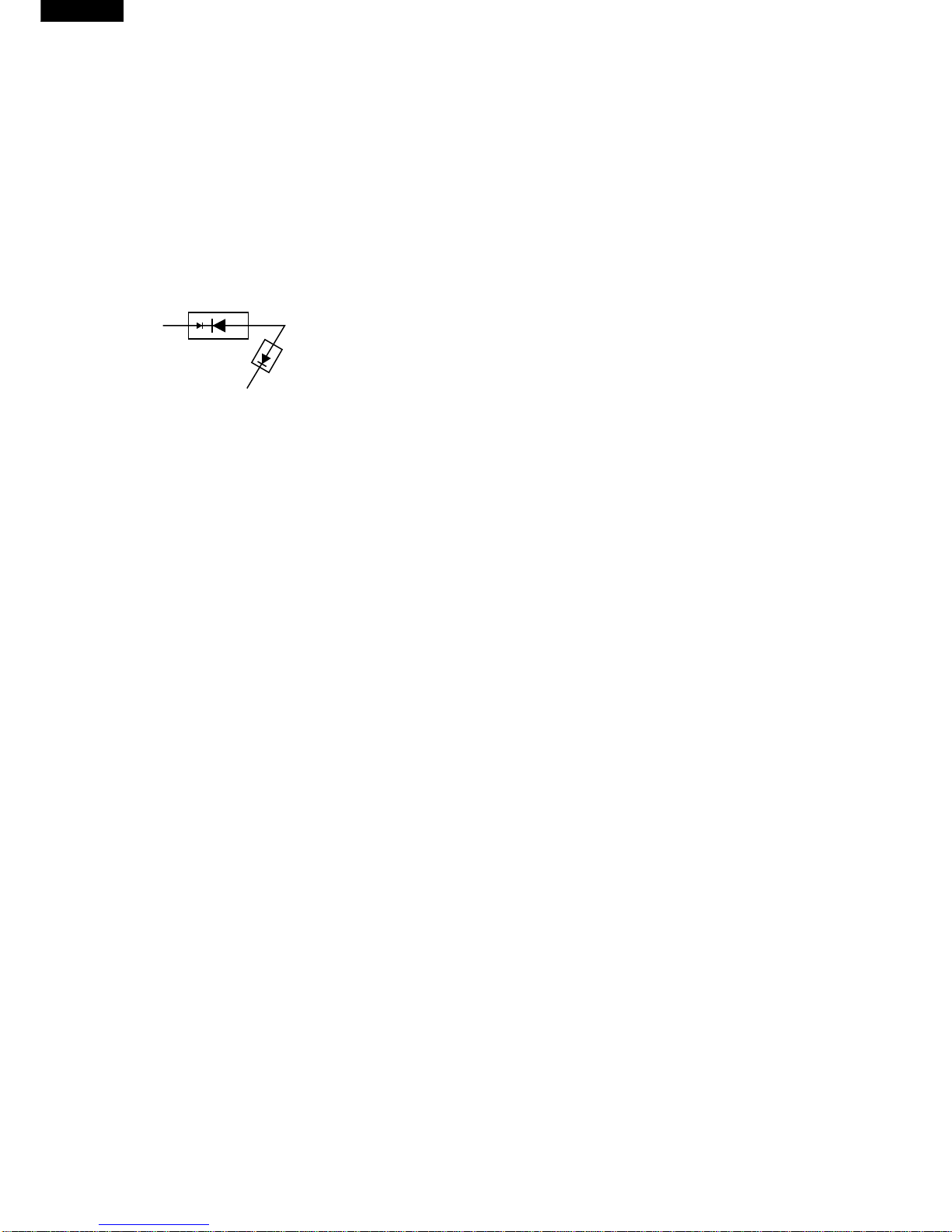
MICROWAVE
AH SENSOR
3. Sensor detects moisture and humidity and calculates
cooking time and variable power.
AH SENSOR COOKING SEQUENCE
1. Incasethe AH sensorcookingcondition isstarted,the
coil of shut-off relays (RY1+RY6) are energized, the
ovenlampandcoolingfanmotorareturnedon,butthe
power transformer is not turned on.
NOTE: TheovenshouldnotbeoperatedonAHSENSOR
COOKING immediately after plugging in the unit.
WaitfiveminutesbeforecookingonAH SENSOR
COOKING CONDITION.
2. After about 16 seconds, the cook relay (RY2) is
energized. The power transformer is turned on,
microwaveenergyisproducedandfirststageisstarted.
The16 secondsis thecooling time required to remove
any vapour from the oven cavity and sensor.
(Figure O-2)
NOTE: During this first stage, do not open the door or
touch STOP/CLEAR pad.
3. The oven will go to the Mix Cooking Condition at the
2nd. or 3rd. stage when Reheat pie, Casseroles or
Desserts has been chosen. (Figure O-4)
4. When the sensor detects the vapour emitted from the
food,thedisplayswitchesovertotheremainingcooking
timeandthetimercountsdowntozero.Atthistime,the
door may be opened to stir food, turn it or season, etc.
NOTE: In case where a small quantity of food is cooked,
theovenwillstopwithoutdisplayingtheremaining
cooking time.
5. Whenthetimerreacheszero,anaudiblesignalsounds.
The shut-off relay (RY1+RY6) and cook relay (RY2)
are de-energized and the power transformer, oven
lamp, etc. are turned off.
6. Opening the door or touching the STOP/CLEAR pad,
the time of day will reappear on the display and the
oven will revert to an OFF condition.
MULTI COOK
MULTI COOK will automatically compute the oven tem-
perature, microwave power and cooking time for baking
and roasting. Set the desired program by touching the
MULTI COOK pad, and number pad. Enter the weight by
touching the Number pads. When the START pad is
touched, the following operations occur:
1. The COOK indicator will light and the Microwave
Symbol and/or the Convection Fan Symbol will rotate.
2. The cooking time will appear on the display and start
counting down to zero. The cooking time is adjusted
automatically according to the weight of the food.
3. The shut-off relays (RY1, RY3, RY5 and RY6) are
energized, turning on the oven lamp, turntable motor,
cooling fan motor and convection motor. The power
supply voltage is added to the convection heater.
4. Now, the oven is in the convection cooking mode.
5. When the oven temperature has reached the
programmed convection temperature, the oven goes
into the programmed cooking mode.
6. At the end of the MULTI COOK cycle, the damper is
returnedtotheopenpositionandtheovenwillgotothe
off condition. The cooling fan will remain on until the
oven has cooled.
EASY DEFROST COOKING
The EASY DEFROST key is a special function key to
defrost meats and poultry faster and better.
EASY DEFROST key has 4 defrost stages.
EASY DEFROST automatically defrosts roast beef, etc.
WhenEASYDEFROSTisselectedandthefoodweightis
entered by using the number pads, the oven will cook
according to the special cooking sequence. (Figure O-2)
FIRE SENSING FEATURE (MICROWAVE MODE)
This model incorporates a sensing feature which will stop
the oven's operation if there is a fire in the oven cavity
during microwave cooking.
This accomplished by the LSI repeatedly measures the
voltageacrossthetemperaturemeasurementcircuit(ther-
mistor) during it's 32-seconds time base comparing the
obtained voltage measurements. If the most recent volt-
age measured is 300mV grater than the previous voltage
measured,theLSIjudgesitasafireintheovencavityand
switchesofftherelaystothepowertransformer,fanmotor
and convection motor. The LSI also stops counting down
and closes the damper door so that no fresh air will enter
the oven cavity. Please refer to the following section for a
more detailed description.
Operation
Please refer to the timing diagrams below.
1. Thethermistoroperateswithina32-secondstimebase
and it is energized for three (3) seconds and off for 29
seconds. Two (2) seconds after the thermistor is
energized, the voltage across the temperature
measurementcircuit is sampled by theLSI and twenty
one (21) seconds after the thermistor is cut off the LSI
turns on the cooling fan for six (6) seconds.
2. The above procedure is repeated. If the difference
between the first voltage measured (in step 1) and the
voltage measured when the procedure is repeated
(step 2) is greater than 300mV the LSI makes the
judgment that there is a fire in the oven cavity and will
switch off the relays to the power transformer, fan
motor and convection motor. The LSI also stops
counting down and closes the damper door so that no
fresh air will enter the oven cavity.
3. Oncethefiresensorfeaturehasshuttheunitdown,the
programmed cooking cycle may be resumed by
pressing the "START" pad or the unit may be reset by
pressing the "CLEAR" pad.

R-9H58
7
UPPER AND LOWER LATCH SWITCHES
Those latch switches are mounted in the latch hooks as
shown in figure. They are activated by the latch heads on
the door.
Whenthedoorisopened,theswitchesinterruptthecircuit
toallcomponentsexceptCPUunitandrelayunitandoven
lamp.Acookcyclecannottakeplaceuntilthedoorisfirmly
closed thereby activating both interlock switches.
LATCH HOOK
STOP SWITCH
MONITOR SWITCH
SWITCH LEVER
OPEN LEVER
LATCH
HEADS
DOOR OPEN
BUTTON
UPPER LATCH SWITCH
LOWER LATCH SWITCH
Figure D-1. Switches
MONITOR SWITCH
The monitor switch is mounted on the latch hook. It is
activated (the contacts opened) by the lower latch head
when the door is closed. The switch is intended to render
theoven inoperative by means ofblowning the fuse when
the contacts of the common and normal open contacts of
upper latch switch and lower latch switch
fail to open when the door is opened.
Functions:
1. When the door is opened, the monitor switch contacts
close (to the ON condition) due to their being normally
closed. At this time the common and normal open
contacts of upper latch switch and lower latch switch
are in the OFF condition (contacts open) due to their
being normally open contacts switch.
2. As the door goes to a closed position, the monitor
switchcontacts are first opened and then the common
and normal open contacts of upper latch switch close.
(On opening the door, each of these switches operate
inversely.)
3 If the door is opened during cooking, and the common
and normal open contacts of upper latch switch and
IMPORTANT:
During sensor cooking operation, the fire sensing
operationsequencewillnotbeginuntil the AH sensor
has detected vapours and initiated a sensor cooking
cycle.Thisisbecausetheoperationoftheconvection
fanwouldinterferewiththeAHsensor'svapourdetec-
tion.
CONVECTION
MOTOR
THERMISTOR
Sensing
Voltage
ON
OFF
ON
OFF
ON
OFF
0 2 24 30 64 (sec.)
3 sec.
Sensing the voltage across the temperature measurement circuit.
6 sec.
332 (sec.)
FUNCTION OF IMPORTANT COMPONENTS
lower latch switch fail to open, the fuse blows
simultaneously with closing of the monitor switch
contacts.
CAUTION: BEFORE REPLACING A BLOWN FUSE
TESTTHEUPPERLATCHSWITCH,LOWER
LATCH SWITCH AND MONITOR SWITCH
FOR PROPER OPERATION. (REFER TO
CHAPTER “TEST PROCEDURE”).
STOP SWITCH
The stop switch is activated by the latch head.
When the door is opened while the oven is in cook cycle,
the stop switch contacts open to de-energize the relay
(RY-1,RY-2,RY-3,RY-5,RY-6). Then the cook cycle is
stopped.
THERMAL CUT-OUT 150˚C (OVEN)
The oven thermal cut-out located on the left side of the
thermalprotectionplateisdesignedtopreventdamageto
the convection heater unit if an overheated condition
develops in the tube due to cooling fan failure, obstructed
air ducts, dirty or blocked air intake, etc. Under normal
operation,theoventhermalcut-out remains closed.How-
ever, when abnormally high temperatures are reached
within the heater unit, the oven thermal cut-out will open,
causingtheoventoshutdown.Whentheovenhascooled
temperature, the oven thermal cut-out closes.
THERMAL CUT-OUT 95˚C (FAN MOTOR)
The thermal cut-out protect the fan motor against over-
heating. If its temperature goes up higher than 95˚C
because the fan motor is locked or the ventilation operat-
ing are blocked, the contacts of the thermal cut-out will
open and switch off the oven. When the thermal cut-out
cools itself down to 75˚C, the contacts of the thermal cut-
out will close again.
TEMPERATURE FUSE 150˚C (MG)
This fuse protects the magnetron against overheating. If
the temperature goes up higher than 150˚C because the
fan motor is interrupted, the air inlet duct is blocked or the
ventilation openings are obstructed, the fuse blows and
cutsoffthepowersupplyingtothepowertransformer.The
defective fuse must be replaced with new rated one.
FUSE M8A 250V
1. If the wire harness or electrical components are short-
circuited,thisfuseblowstopreventanelectricshockor
fire hazard.

R-9H58
8
2. The fuse also blows when upper latch switch and
lower latch switch remain closed with the oven door
open and when the monitor switch closes.
3. The fuse M8A also blows when asymmetric rectifier,
H.V. rectifier, H.V. wire harness, H.V. capacitor,
magnetronorsecondarywindingofpowertransformer
is shorted.
ASYMMETRIC RECTIFIER
The asymmetric rectifier is a solid state device that
preventscurrentflowinsbothdirections.And itprevents
thetemperatureriseofthepowertransformerbyblowing
the fuse M8A when the high voltage rectifier is shorted.
roundingthemagnetronandcoolsthemagnetron.Thisair
is channelled through the oven cavity to remove steam
and vapours given off from the heating foods. It is then
exhausted through the exhausting air vents at the oven
cavity.
CONVECTION HEATER
The convection heater is located at the rear of the oven
cavity. It is intended to heat air driven by the convection
fan.Theheatedairiskeptintheovenandforce-circulated
and reheated by the convection heater.
CONVECTION COOKING SYSTEM
Thisovenis designed withahot air heatingsystemwhere
foodis not directly heated by the convection heater, but is
heatedby forced circulation of the hot air produced by the
convection heater. The air heated by the convection
heater is circulated through the convection passage pro-
vided on the outer casing of the oven cavity by means of
the convection fan which is driven by the convection
motor.Itthenenterstheinsideoftheoventhroughthevent
holesprovidedontheleftsideoftheoven.Next,thehotair
heatsthefood on theturntableand leaves theovencavity
through the vent in the oven cavity left side wall. Without
leavingtheoven,thishotairis reheatedbytheconvection
heater, passes through the convection passage and en-
ters the inside of the oven cavity again, in a continuing
cycle. In this way, the hot air circulates inside the oven
cavity to raise its temperature and, at the same time,
comes into contact with the food being cooked. When the
temperature inside the oven cavity reaches the selected
temperature,theconvectionheaterisde-energized.When
the temperature inside the oven cavity drops below the
selected temperature, the convection heater is energized
again. In this way, the inside of the oven cavity is main-
tained at approximately the selected temperature.
When the convection time reaches 0, the convection
heater is de-energized and the convection fan stops
operating and the oven shuts off. Upon completion of the
cookingtime,theaudiblesignalwillsound,andovenlamp,
turntable motor, cooling fan motor and convection motor
arede-energized.Attheendoftheconvectioncycle,ifthe
cavity air temperature is above 116˚C, the circuit to RY6
will be maintained (by the thermistor circuit) to continue
operation of the cooling fan motor until the temperature
drops below 116˚C, at which time the relay will be de-
energized, turning off the fan motor. Relay RY5 will how-
ever, open as soon as the convection cycle has ended,
turningofftheconvectionfanmotor.Thiswillnowcooland
allow the damper door to open.
DAMPER OPEN-CLOSE MECHANISM
Usually, the damper is in the open position except during
convection cooking.
Damper position is set automatically by damper motor,
damper switch, motor cam and damper shaft.
Thesecomponents are operated by asignal that judges if
microwave cooking or convection cooking operation is
selected by the CPU unit.
Microwave Cooking:
Damper is in the open position, because a portion of
cooling air is channelled through the cavity to remove
steam and vapours given off from the heating foods.
The rated peak reverse voltage of D1 of the asymmetric
rectifier is 6 KV The rated peak reverse voltage of D2 of
the asymmetric rectifier is 1.7 KV. D1 and D2 of the
asymmetric rectifier or high voltage rectifier are shorted
when the each peak reverse voltage goes beyond the
each rated peak reverse voltage. (The process of blow-
ing the fuse M8A.) .
1. The high voltage rectifier is shorted by any causes
when microwave cooking.
2. The peak reverse voltage of D2 of the rectifier goes
beyond the rated peak reverse voltage 1.7 KV in the
voltagedoubler circuit.
3. D2 of the rectifier is shorted.
4. The large electric currents flow through the high
voltage winding of the power transformer.
5. The large electric currents beyond 8A flow through
the primary winding of the power transformer.
6. The fuse M8A blows by the large electric currents.
7. Thepower supplyto the power transformer iscut off.
THERMISTOR
The thermistor is a negative temperature coefficient
type. The temperature in the oven cavity is detected
through the resistance of the thermistor, and then the
controlunitcausestheheatingelementrelaytooperate,
thus the current to the heating element is turned ON/
OFF.
MONITOR RESISTOR
The monitor resistor prevents the fuse M8A 250V burst-
ingwhen the fuse M8A 250V blows dueto the operation
of the monitor switch.
TURNTABLE MOTOR
Theturntablemotordrivestheturntablesupportingplate
to rotate the turntable.
CONVECTION MOTOR
The convection motor drives the convection fan and
provides the heated air.
FAN MOTOR
The fan motor drives a blade which draws external cool
air. This cool air is directed through the air vanes sur-
D2 D1
ASYMMETRIC
RECTIFIER
HIGH VOLTAGE RECTIFIER
AB
C

R-9H58
9
It is then exhausted at the top of the oven cavity into a
condensation compartment.
Convection Cooking:
Damper is in the closed position, so that no hot air will be
allowed to leak out the oven cavity.
Damper Operation
1. When power supply cord is plugged in:
1-1. When power supply cord is plugged in, a signal is
sensedinthecontrolunit,andoperates shut-offrelay
(RY4).
1-2. Contacts of shut-off relay (RY4) close, the damper
motor is energized, opening the damper door.
1-3. When the damper is moved to the open position by
the damper cam, damper switch is closed (ON
position).
1-4. The signal of damper switch is re-sensed in the
control unit and shut-off relay (RY4) is turned off.
1-5. Theratedvoltagetothedampermotorisstoppedand
the motor turns off.
2. When oven is microwave cooking:
Damper is in the open position
3. When oven is convection cooking:
3-1 Dampermotorisenergizedbytouchingtheconvection,
temperature and START pads.
3-2. When damper is in the closed position (damper
switchisOFF),itssignalissensedbythecontrolunit,
and shut-off relay (RY4) is de-energized.
3-3. The damper is held in the closed position during the
convection cooking operation.
3-4. At the end of the convection cooking, shut-off relay
(RY4)isenergized,andthedamperisreturnedtothe
open position.
NOTE: If the damper door is not in the proper position,
closed during convection or open during
microwave,thecontrolunitwillstopovenoperation
after 1 minute.
Cooking Mode Operation of Damper
Microwave cooking OPEN
Convection cooking CLOSE
Sensor cooking OPEN
Automatic mix cooking CLOSE
Grill cooking CLOSE
Slow cooking CLOSE
DAMPER DUCT
DAMPER
DAMPER CAM
DAMPER MOTOR
DAMPER SWITCH
DAMPER SHAFT
Figure D-2. Damper Mechanism
NOISE FILTER
The noise filter prevents the radio frequency interference
that might flow back in the power circuit.

R-9H58
10
SERVICING
WARNING TO SERVICE PERSONNEL
Microwaveovenscontaincircuitry capable ofproducingveryhigh voltage andcurrent,contact with anypartofthe
highvoltagecircuitwillresultinelectrocution.Highvoltagecapacitor,Powertransformer,Magnetron,Highvoltage
rectifier assembly, High voltage harness.
REMEMBER TO CHECK 4R
1) Reconnect all leads removed from components
during testing.
2) Replace the outer case (cabinet).
3) Reconnect the supply.
4) Run the oven. Check all functions.
Microwave ovens should not be run empty. To test for
the presence of microwave energy within a cavity,
place a cup of cold water on the oven turntable, close
the door and set the microwave timer for two (2)
minutes. Set the power level to HIGH and push the
START button. When the two minutes has elapsed
(timeratzero)carefullycheckthatthewaterisnowhot.
If the water remains cold carry out 3D checks and re-
examine the connections to the component being
tested.
IMPORTANT: If the oven becomes inoperative because
of a blown fuse M8A in the upper latch
switch-lowerlatchswitch-monitorswitch
- monitor resistor circuit, check the upper
latch switch, lower latch switch, monitor
switchand monitorresistorbeforereplac-
ing the fuse M8A.
REMEMBER TO CHECK 3D
1) Disconnect the supply.
2) Door opened, and wedged open.
3) Discharge high voltage capacitor.
WARNING: AGAINST THE CHARGE OF THE
HIGH-VOLTAGE CAPACITOR
Thehigh-voltagecapacitorremainschargedabout
60 seconds after the oven has been switched off.
Wait for 60 seconds and then short-circuit the
connectionofthehigh-voltagecapacitor(thatis,of
the connecting lead of the high-voltage rectifier)
against the chassis with the use of an insulated
screwdriver.
Sharprecommendthatwhereverpossiblefault-finding
is carried out with the supply disconnected. It may in,
some cases, be necessary to connect the supply after
the outer case has been removed, in this event carry
out 3D checks and then disconnect the leads to the
primary of the power transformer. Ensure that these
leads remain isolated from other components and the
ovenchassis.(Useinsulationtapeifnecessary.)When
the testing is completed carry out 3D checks and
reconnect the leads to the primary of the power trans-
former.
When all service work is completed, and the oven is fully assembled, the microwave power output should be
checked and microwave leakage test carried out
When troubleshooting the microwave oven, it is helpful to
follow the Sequence of Operation in performing the
checks.Manyofthepossiblecausesoftroublewillrequire
that a specific test be performed. These tests are given a
procedureletterwhichwillbefoundinthe"TestProcedure
"section.
TROUBLESHOOTING GUIDE

R-9H58
11
Home fuse blows when
powersupplycordisplugged
into wall outlet.
FuseM8Ablowswhenpower
cordisplugged into wallout-
let.
Display does not show any-
thingwhenpowercordisfirst
plugged into wall outlet.
Display does not operate
properly when STOP/
CLEARpadistouched.(The
timeofdayshouldappearon
the display with beep sound
during normal condition.)
Ovenlampdoesnotlightwith
door opened.
Ovenlampdoes notlightatall
Oven lamp light, but turnta-
ble motor does not operate.
Cooling fan motor does not
operate.
Theovenstopsafter1minute
Ovendoesnotgointoacook
cycle, when START pad is
touched.
Lowornopowerisproduced
during microwave cooking
(The food is heated incom-
pletely or not heated at all)
Extremelyunevenheatingis
producedinovenload(food).
Function of variable cooking
doesnotoperateproperlyex-
cept HIGH power.
CONV indicator lights, but
heating element does not
heat.
Temperatureintheovencav-
ity is lower or higher than
preset.
Convection cycle runs 1
minute then the oven shuts
down.
Convectioncycleruns3min-
utes then the oven shuts
down.
Oven is in the sensor cook-
ing condition but AH sensor
does not end 1st. stage or
does not stop cooking cycle
or the oven stops soon.
MAGNETRON
POWER TRANSFORMER
H.V. RECTIFIER ASSEMBLY
HIGH VOLTAGE CAPACITOR
LATCH AND STOP SWITCHES
MONITOR SWITCH
DAMPER SWITCH
MAIN FUSE
TEMPERATURE FUSE 150˚C
THERMAL CUT-OUT
CONVECTION HEATER
THERMISTOR
FAN MOTOR
TURNTABLE MOTOR
CONVECTION MOTOR
DAMPER MOTOR
MONITOR RESISTOR
TOUCH CONTROL PANEL
KEY UNIT
RELAY (RY-1)
RELAY (RY-2)
RELAY (RY-3)
RELAY (RY-4)
RELAY (RY-5)
RELAY (RY-6)
FOIL PATERN ON P.W.B.
AH. SENSOR
OVEN LAMP OR SOCKET
O
PENED OR SHORTED WIRE HARNESS
WALL OUTLET
LOW POWER SUPPLY VOLTAGE
SHORTED POWER CORD
NOISE FILTER
CK = Check / RE = Replace
OFF
CONDITION
ABC
D
EEEFGGHI JJ J JKMNOOOOOOPQRE CKCK CK RE L
COOKING
CONDITION
(MICROWAVE)
PROBLEM
CONDITION
TEST PROCEDURE
POSSIBLE CAUSE
AND
DEFECTIVE PARTS
(AH. SENSOR)
(CONVECTION)

R-9H58
12
TEST PROCEDURES
PROCEDURE
LETTER COMPONENT TEST
AMAGNETRON TEST
NEVER TOUCH ANY PART IN THE CIRCUIT WITH YOUR HAND OR AN INSULATED TOOL
WHILE THE OVEN IS IN OPERATION.
CARRY OUT 3D CHECK.
Isolatethe magnetron from high voltage circuit by removing all leads connectedto filament terminal.
Totestforanopencircuitfilamentuseanohmmetertomakeacontinuitytestbetweenthemagnetron
filament terminals, the meter should show a reading of less than 1 ohm.
Totestforshortfilamenttoanodecondition,connectohmmeterbetweenoneofthefilamentterminals
and the case of the magnetron (ground). This test should be indicated an infinite resistance. If a low
or zero resistance reading is obtained then the magnetron should be replaced.
MICROWAVE OUTPUT POWER (1 Litre water load)
The following test procedure should be carried out with the microwave oven in a fully assembled
condition (outer case fitted). Microwave output power from the magnetron can be measured by way
of IEC 705, i.e. it can be measured by using water load how much it can be absorbed by the water
load.Tomeasurethemicrowaveoutputpowerinthemicrowaveoven,therelationofcalorieandwatt
is used. When P(W) heating works for t(second), approximately P x t/4.187 calorie is generated. On
theotherhand,ifthe temperature ofthewaterwith V(ml) rises∆T (°C)during this microwaveheating
period, the calorie of the water is V x ∆T.
The formula is as follows;
P x t / 4.187 = V x ∆T P (W) = 4.187 x V x ∆T / t
Our condition for water load is as follows:
Room temperature..............around 20°C Power supply Voltage.........Rated voltage
Water load.........1000 g Initial temperature...........10±2°C Heating time.........49 sec.
P = 85 x ∆T
Measuring condition:
1. Container
The water container must be a cylindrical borosilicate glass vessel having a maximum material
thickness of 3 mm and an outside diameter of approximately 190 mm.
2. Temperature of the oven and vessel
The oven and the empty vessel are at ambient temperature prior to the start the test.
3. Temperature of the water
The initial temperature of the water is (10±2)°C.
4. Select the initial and final water temperature so that the maximum difference between the final
water temperature and the ambient temperature is 5°C.
5. Selectstirringdevicesandmeasuringinstrumentsinordertominimizeadditionorremovalofheat.
6. The graduation of the thermometer must be scaled by 0.1°C at minimum and accurate
thermometer.
7. The water load must be (1000±5) g.
8. “t”ismeasuredwhilethemicrowavegeneratorisoperatingatfullpower.Magnetronfilamentheat-
up time is not included.
NOTE: The operationtimeofthe microwave ovenis“t+2”sec.2 sec. ismagnetronfilamentheat-uptime.
Measuring method:
1. Measure the initial temperature of the water before the water is added to the vessel.
(Example: The initial temperature T1 = 11°C)
2. Add the 1 litre water to the vessel.
3. Place the load on the centre of the shelf.
4. Operate the microwave oven at HIGH for the temperature of the water rises by a value ∆T of
(10 ±2)°C.
5. Stir the water to equalize temperature throughout the vessel.
6. Measure the final water temperature. (Example: The final temperature T2 = 21°C)
7. Calculate the microwave power output P in watts from above formula.

R-9H58
13
TEST PROCEDURES
PROCEDURE
LETTER COMPONENT TEST
Initial temperature............................................................................................. T1 = 11°C
Temperature after (49 + 2) = 51 sec................................................................. T2 = 21°C
Temperature difference Cold-Warm ............................................................... ∆T1 = 10°C
Measured output power
The equation is “P = 85 x ∆T”..................................................P = 85 x 10°C = 850 Watts
JUDGMENT: The measured output power should be at least ±15 % of the rated output power.
CAUTION: 1°C CORRESPONDS TO 85 WATTS REPEAT MEASUREMENT IF THE POWER IS
INSUFFICIENT.
1000g
1000g
1000g
T1˚C T2˚C
Heat up for51 sec.
B POWER TRANSFORMER TEST
WARNING: High voltages and large currents are present at the secondary winding and
filamentwindingofthepowertransformer.Itisverydangeroustoworknearthis
part when the oven is on. NEVER make any voltage measurements of the high-
voltage circuits, including the magnetron filament.
CARRY OUT 3D CHECKS.
Disconnect the leads to the primary winding of the power transformer. Disconnect the filament and
secondary winding connections from the rest of the HV circuitry. Using an ohmmeter, set on a low
range, it is possible to check the continuity of all three windings. The following readings should be
obtained:
a. Primary winding ................... approx. 1.3 Ω
b. Secondary winding............... approx. 72 Ω
c. Filament winding .................. less than 1Ω
If the reading obtained are not stated as above, then the power transformer is probably faulty and
should be replaced.
CARRY OUT 4R CHECKS.
HIGH VOLTAGE RECTIFIER TEST
CARRY OUT 3D CHECKS.
IsolatethehighvoltagerectifierassemblyfromtheHVcircuit.Thehighvoltagerectifier canbetested
using an ohmmeter set to its highest range. Connect the ohmmeter across the terminal B+C of the
high voltage rectifier and note the reading obtained. Reverse the meter leads and note this second
reading.Thenormalresistanceisinfiniteinonedirectionandmorethan100kΩintheotherdirection.
CARRY OUT 4R CHECKS.
ASYMMETRIC RECTIFIER TEST
CARRY OUT 3D CHECKS.
Isolate the high voltage rectifier assembly from the HV circuit. The asymmetric can be tested using
an ohmmeter set to its highest range across the terminals A+B of the asymmetric rectifier and note
the reading obtained. Reverse the meter leads and note this second reading. If an open circuit is
indicated in both direction then the asymmetric rectifier is good. If an asymmetric rectifier is shorted
in either direction, then the asymmetric rectifier is probably faulty and must be replaced with high
voltage rectifier. When the asymmetric rectifier is defective, check whether magnetron, high voltage
AB
C
D2 D1
ASYMMETRIC
RECTIFIER
HIGH VOLTAGE RECTIFIER
C HIGH VOLTAGE RECTIFIER ASSEMBLY TEST

R-9H58
14
TEST PROCEDURES
PROCEDURE
LETTER COMPONENT TEST
rectifier, high voltage wire or filament winding of the power transformer is shorted.
CARRY OUT 4R CHECKS.
NOTE: FORMEASUREMENTOFTHE RESISTANCE OF THE RECTIFIER, THE BATTERIES OFTHE
MEASURING INSTRUMENT MUST HAVE A VOLTAGE AT LEAST 6 VOLTS, BECAUSE
OTHERWISE AN INFINITE RESISTANCE MIGHT BE SHOWN IN BOTH DIRECTIONS.
CARRY OUT 3D CHECKS.
A. Isolate the high voltage capacitor from the circuit.
B. Continuity check must be carried out with measuring instrument which is set to the highest resistance
range.
C. A normal capacitor shows continuity for a short time (kick) and then a resistance of about 10MΩafter
it has been charged.
D. A short-circuited capacitor shows continuity all the time.
E. Anopencapacitorconstantlyshowsaresistanceabout10MΩbecauseofitsinternal10MΩresistance.
F. When the internal wire is opened in the high voltage capacitor shows an infinite resistance.
G. The resistance across all the terminals and the chassis must be infinite when the capacitor is normal.
If incorrect reading are obtained, the high voltage capacitor must be replaced.
CARRY OUT 4R CHECKS.
CARRY OUT 3D CHECKS.
1. IfthefuseM8Aisblown,therecouldbeshortsorgroundsinelectricalpartsorwireharness.Check
them and replace the defective parts or repair the wire harness.
2. IfthefuseM8Aisblownwhenthedoorisopened,checktheupperlatchswitch,lowerlatchswitch,
monitor switch and monitor resistor.
If the fuse M8A is blown by incorrect door switching, replace the defective switch(s) and the fuse
M8A.
3. IfthefuseM8Aisblown,therecouldbeshortintheasymmetricrectifierorthereisagroundinwire
harness. A short in the asymmetric rectifier may have occured due to short or ground in H.V.
rectifier,magnetron, powertransformer or H.V. wire. Checkthem andreplace the defective parts
or repair the wire harness.
CARRY OUT 4R CHECKS.
CAUTION: Only replace fuse with the correct value replacement.
D HIGH VOLTAGE CAPACITOR TEST
ESWITCH TEST
CARRY OUT 3D CHECKS.
Isolate the switch to be tested and using an ohmmeter check between the terminals as described in the
following table.
Table: Terminal Connection of Switch
Plunger Operation COM to NO COM to NC COM;Common terminal
Released Open Circuit Short Circuit NO; Normally open terminal
Depressed Short Circuit Open Circuit NC; Normally close terminal
If incorrect readings are obtained, make the necessary switch adjustment or replace the switch.
CARRY OUT 4R CHECKS.
F BLOWN FUSE F M8A
GTEMPERATURE FUSE AND THERMAL CUT-OUT TEST
CARRY OUT 3D CHECKS.
Disconnect the leads from the terminals of the temp. fuse or thermal cut-out. Then using an
ohmmeter, make a continuity test across the two terminals as described in the table below.
CARRY OUT 4R CHECKS.

R-9H58
15
TEST PROCEDURES
PROCEDURE
LETTER COMPONENT TEST
CARRY OUT 3D CHECKS.
Disconnect connector-E from the CPU unit. Measure the resistance of the thermistor with an
ohmmeter. Connect the ohmmeter leads to Pin No’s E-3 and E-4 of the thermistor harness.
Room Temp. .................. 20˚C - 30˚C
Resistance ..................... Approx. 350kΩ- 155kΩ
If the meter does not indicate above resistance, replace the thermistor.
CARRY OUT 4R CHECKS.
I THERMISTOR TEST
Table: Temperature Fuse and Thermal cut-out Test
Temperature of “ON” condition Temperature of “OFF” condition Indication ofohmmeter
Parts Name (closed circuit) (˚C) (open circuit) (˚C) (When room temperature
is approx. 20˚C)
Temp. fuse 150˚C This is not resetable type. Above 150 ˚C Closed circuit
Thermal cut-out 150˚C Below 130˚C Above 150˚C Closed circuit.
Thermal cut-out 95˚C Below 75˚C Above 95˚C Closed circuit.
If incorrect readings are obtained, replace the temp. fuse or thermal cut-out.;
Anopencircuittemperaturefuse150˚C(MG)indicatesthatthemagnetronhasoverheated,thismay
be due to resistricted ventilation, cooling fan failure or a fault condition within the magnetron or HV
circuit.
An open circuitthermal cut-out 150˚C (OVEN) indicates that the convection motor has over heated,
this may be due to convection motor locked.
An open circuit thermal cut-out 95˚C (FM) indicates that the fan motor winding has overheated, this
may be due to blocked ventilation or locked cooling fan.
CARRY OUT 3D CHECKS.
Before carring out the following tests make sure the heater is fully cool.
1. Resistance of heater
Disconnectthe wireleads tothe heater to be tested. Using ohmmeter with lowresistance range.
Check the resistance across the terminals of the heater.
The resistance of heater is approximately 37.5 ohms.
2. Insulation resistance
Disconnectthewireleadstotheheatertobetested.Checktheinsulationresistancebetweenthe
elementandcavity using a500V- 100Mohms insulationtester.The insulation resistanceshould
be more than 10Mohms in the cold start.
If the results of above test 1 and/or 2 are out of above specifications, the heater is probably faulty
and should be replaced.
CARRY OUT 4R CHECKS.
H CONVECTION HEATER TEST
JMOTOR WINDING TEST
CARRY OUT 3D CHECKS.
Disconnect the leads from the motor.
Usinganohmmeter,checktheresistancebetweenthetwoterminalsasdescribedinthetablebelow.
Table: Resistance of Motor
Motors Resistance
Fan motor Approximately 295 Ω
Turntable motor Approximately 10.5 kΩ
Convection fan motor Approximately 210 Ω
Damper motor Approximately 11 kΩ

R-9H58
16
TEST PROCEDURES
PROCEDURE
LETTER COMPONENT TEST
If incorrect readings are obtained, replace the motor.
CARRY OUT 4R CHECKS.
CARRY OUT 3D CHECKS.
Disconnect the leads from the monitor resist. Using an ohmmeter and set on a low range. Check
between the terminals of the monitor resistor.
The resistance of monitor resistor is approx. 0.8 ohms.
If incorrect readings are obtained, replace the monitor resistor.
CARRY OUT 4R CHECKS.
ThetouchcontrolpanelconsistsofcircuitsincludingsemiconductorssuchasLSI,ICs,etc.Therefore,
unlike conventional microwave ovens, proper maintenance cannot be performed with only a
voltmeterandohmmeter.Inthisservicemanual,thetouchcontrolpanelassemblyisdivided intotwo
units, Control Unit and Key Unit and troubleshooting by unit replacement is described according to
the symptoms indicated.
1. Key Unit. Note: Check key unit ribbon connection before replacement.
The following symptoms indicate a defective key unit. Replace the key unit.
a) When touching the pads, a certain pad produces no signal at all.
b) When touching a number pad, two figures or more are displayed.
c) When touching the pads, sometimes a pad produces no signal.
2. Control Unit.
The following symptoms indicate a defective control unit. Replacethe control unit.
2-1 In connection with pads.
a) When touching the pads, a certain group of pads do not produce a signal.
b) When touching the pads, no pads produce a signal.
2-2 In connection with indicators.
a) At a certain digit, all or some segments do not light up.
b) At a certain digit, brightness is low.
c) Only one indicator does not light.
d) The corresponding segments of all digits do not light up; or they continue to light up.
e) Wrong figure appears.
f) A certain group of indicators do not light up.
g) The figure of all digits flicker.
K MONITOR RESISTOR TEST
L NOISE FILTER TEST.
CARRY OUT 3D CHECKS.
Disconnectthe leads fromthe terminalsof thenoise
filter.Using an ohmmeter, check between the termi-
nals as described in the following table.
If incorrect readings are obtained, replace the noise
filter unit.
FUSE
M8A
LN
RESISTOR 680K / 0.5W
LINE CROSS CAPACITOR 0.22µ / AC 250V
noise suppression coil
RESISTOR 10M / 0.5W
LINE BYPASS
CAPACITOR
0.0022µ /AC 250V
LINE BYPASS
CAPACITOR
0.0022µ /AC 250V
NOISE FILTER
WHT RED
MEASURING POINT INDICATION OF OHMMETER
Between N and L Approx. 680 kΩ
Between terminal N and WHITE Short circuit
Between terminal L and RED Short circuit
CARRY OUT 4R CHECKS.
M TOUCH CONTROL PANEL ASSEMBLY TEST

R-9H58
17
TEST PROCEDURES
PROCEDURE
LETTER COMPONENT TEST
2-3 Other possible troubles caused by defective control unit.
a) Buzzer does not sound or continues to sound.
b) Clock does not operate properly.
c) Cooking is not possible.
d) Proper temperature measurement is not obtained.
If the display fails to clear when the STOP/CLEAR pad is depressed, first verify the flat ribbon is
making good contact, verify that the door sensing switch (stop switch) operates properly; that is the
contacts are closed when the door is closed and open when the door is open.Å@If the door sensing
switch (stop switch) is good, disconnect the flat ribbon that connects the key unit to the control unit
andmakesurethedoorsensingswitchisclosed(eitherclosethedoororshortthedoorsensingswitch
connector).Usethekeyunitmatrix indicated onthecontrolpanelschematicand place ajumperwire
betweenthepinsthatcorrespondtotheSTOP/CLEARpadmakingmomentarycontact.Ifthecontrol
unit responds by clearing with a beep the key unit is faulty and must be replaced. If the control unit
does not respond, it is faulty and must be replaced. If a specific pad does not respond, the above
method may be used (after clearing the control unit) to determine if the control unit or key pad is at
fault.
NKEY UNIT TEST
Remove the outer case and check voltage between Pin No 9 of the 5-pin connector (A) and the
commonterminaloftherelayRY1onthecontrolunitwithanA.C.voltmeter.Themetershouldindicate
230 - 240 volts, if not check oven circuit.
Shut-off, Cook and Heater Relay Test
These relays are operated by D.C. voltage.
Check voltage at the relay coil with a D.C. voltmeter during the microwave cooking operation or
convection cooking operation.
DC. voltage indicated ............... Defective relay.
DC. voltage not indicated ......... Checkdiodewhichisconnectedtotherelaycoil.Ifdiodeisgood,
control unit is defective.
RELAY SYMBOL OPERATIONAL VOLTAGE CONNECTED COMPONENTS
RY1 APPROX. 21.0V D.C. Oven lamp / Turntable motor
RY2(COOK) APPROX. 21.0V D.C. Power transformer
RY3(HEATER) APPROX. 20.0V D.C. Heating element
RY4 APPROX. 21.0V D.C. Damper motor
RY5 APPROX. 21.0V D.C. Convection motor
RY6 APPROX. 21.0V D.C. Cooling fan motor
O RELAY TEST
To protect the electronic circuits, this model is provided with a fine foil pattern added to the primary
onthePWB,thisfoil pattern actsasafuse. If thefoilpatternisopen, follow thetroubleshootingguide
given below for repair.
Problem: POWER ON, indicator does not light up.
P PROCEDURES TO BE TAKEN WHEN THE FOIL PATTERN ON THE PRINTED WIRING BOARD
(PWB) IS OPEN
1
2345
67890
STOP
CLEAR Reheat
Pie
EASY
DEFROST
LESS
POWER
LEVEL
40˚C 70˚C 130˚C 150˚C 160˚C
180˚C 200˚C 220˚C 230˚C 250˚C
HIGH MIX
LOW MIX
CONVEC GRILL
MEMORY
REHEAT
CLOCK
HELP
REHEAT
SENSOR
MULTI
COOK
Frozen
Vegetables
Desserts
Fresh
Vegetables
Jacket
Potato
INSTANT COOK
START
MORE
Casseroles
G 1
G 2
G 3
G 4
G 5 G 6 G 7 G 8 G 9 G10 G11 G12

R-9H58
18
STEPS OCCURRENCE CAUSE OR CORRECTION
1 The rated voltage is not applied between Pin Check supply voltage and oven power cord.
No. 9 of the 5-pin connector (A) and the
common terminal of the relay RY1.
2 The rated voltage is applied to primary Power transformer or secondary circuit defective.
side of power transformer. Check and repair.
3 Only pattern at "a" is broken. *Insert jumper wire J1 and solder.
4 Pattern at "a" and "b" are broken. *Insert the coil RCILF2003YAZZ between "c" and "d".
NOTE: *At the time of making these repairs,
makeavisualinspectionofthevaristor.
check for burned damage and
examine the transformer with an
ohmmeter for the presence of layer
short-circuit (check primary coil
resistance).Ifanyabnormalcondition
isdetected,replacethedefectiveparts.
TEST PROCEDURES
PROCEDURE
LETTER COMPONENT TEST
357 9
3
26
CN - A
VRS1
CONV M FAN M POWER
(J1)
T1
P
a
c
d
b
Checking the initial sensor cooking condition
(1) The oven should be plugged in at least five minutes before sensor cooking.
(2) Room temperature should not exceed 35˚C.
(3)Theunitshouldnotbe installed inanyareawhereheatand steam aregenerated.Theunitshould
not be installed, for example, next to a conventional surface unit. Refer to the "INSTALLATION
Instructions" .
(4) Exhaust vents are provided on the back of the unit for proper cooling and air flow in the cavity. To
permitadequateventilation,besuretoinstallsoasnottoblockthesevents.Thereshouldbesome
space for air circulation.
(5) Be sure the exterior of the cooking container and the interior of the oven are dry. Wipe off any
moisture with a dry cloth or paper towel.
(6) The Sensor works with food at normal storage temperature.For example, chicken pieces would
be at refrigerator temperature and canned soup at room temperature.
(7) Avoid using aerosol sprays or cleaning solvents near the oven while using Sensor settings. The
sensor will detect the vapor given of by the spray and turn off before food is properly cooked.
(8) After the oven is started on sensor cooking condition, if the sensor has not detected the vapor of
the food, ERROR will appear and the oven will shut off.
Water load cooking test
Makesuretheovenhasbeenpluggedinatleastfiveminutesbeforecheckingsensorcookoperation.
The cabinet should be installed and screws tightened.
(1) Fill approximately 200 milliliters (7.2 oz) of tap water in a 1000 milliliter measuring cup.
(2) Place the container on the center of tray in the oven cavity.
(3) Close the door.
(4) Touch REHEAT SENSOR pad twice and touch INSTANT COOK/START pad.Now, the oven is
in the sensor cooking condition and "BEVE-", "RAGE", "SOUP", "SENSOR" and "REHEAT" will
appear in the display.
(5) The oven will operate for the first 16 seconds, without generating microwave energy.
Whenthe AHsensor isdefective (open or short), ERROR will appear in thedisplay after16 seconds
cleaning time.
If ERROR appears check sensor wire connections and/or AH sensor.
NOTE: ERROR will appear if the door is opend or STOP/CLEAR pad is touched during first stage of
sensor cooking.
(6) After approximately 16 seconds, microwave energy is produced, and the display should start to
count down the remaining cooking time and oven should turn off when water is boiling (bubling).
If the oven does not turn off, replace the AH sensor or check the control unit, refer to explanation
below.
QAH SENSOR TEST
Other manuals for R-9H58
1
Table of contents
Other Sharp Microwave Oven manuals

Sharp
Sharp R-190HK/HW User manual

Sharp
Sharp R-820BK User manual

Sharp
Sharp R-320EK User manual

Sharp
Sharp EBR-4900 Series User manual

Sharp
Sharp R-333F User manual

Sharp
Sharp R-933S User manual

Sharp
Sharp R-580D User manual

Sharp
Sharp R-953(SL)M User manual

Sharp
Sharp R-340F Use and care manual

Sharp
Sharp R-320DK User manual

Sharp
Sharp R-898CS Technical specifications

Sharp
Sharp Carousel R-405D User manual

Sharp
Sharp R-420E User manual

Sharp
Sharp R-510HK/HW User manual

Sharp
Sharp R-32FBST User manual

Sharp
Sharp R-770B User manual

Sharp
Sharp R-27STM User manual

Sharp
Sharp Carousel R-880F User manual

Sharp
Sharp R-426HS User manual

Sharp
Sharp CAROUSEL R-530E Use and care manual