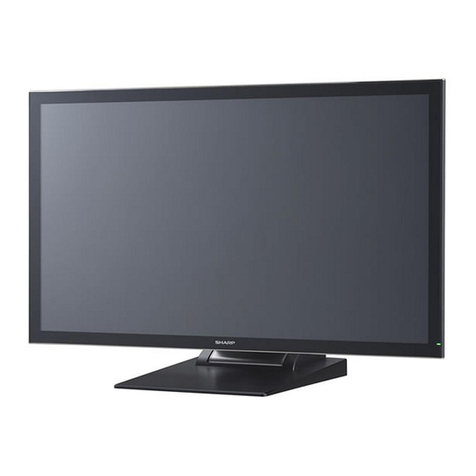
Sharp PN-K321 User manual

SERVICE MANUAL
CODE: 00ZPNK321SM2E
LCD MONITOR
MODEL PN-K321/K321H/K322B/K322BH
CHAPTER 1. OUTLINE OF THE PRODUCT ······················································· 1-1
CHAPTER 2. INSTALLATION,ADJUSTMENT,SETTING ··································· 2-1
CHAPTER 3. INPORTANT INFORMATION FOR SERVICING THE DISPLAY··· 3-1
CHAPTER 4.
SERVICE MENU/VARIOUS SETTING TOOL OPERATING PROCEDURES
······· 4-1
CHAPTER 5. FIRMWARE UPDATE PROCEDURES ·········································· 5-1
CHAPTER 6. DISASSEMBLY AND ASSEMBLY ················································ 6-1
CHAPTER 7. TOROUBLESHOOTING ································································ 7-1
CHAPTER 8. HARDWARE DESVCRIPTIONS ···················································· 8-1
SHARP CORPORATION
CONTENT
T
his document has been published to be used for
after sales service only.
The contents are subject to change without notice.
Parts marked with “!” are important for maintaining the safety of the set. Be sure to replace these
parts with specified ones for maintaining the safety and performance of the set.

<Solder composition code of lead-free solder>
Solder composition Solder composition code
Sn-Ag-Cu a
Sn-Ag-Bi
Sn-Ag-Bi-Cu b
Sn-Zn-Bi z
Sn-In-Ag-Bi i
Sn-Cu-Ni n
Sn-Ag-Sb s
Bi-Sn-Ag-P
Bi-Sn-Ag p
(1) NOTE FOR THE USE OF LEAD-FREE SOLDER THREAD
When repairing a lead-free solder PWB, use lead-free solder thread. Never use conventional lead solder thread, which may cause a
breakdown or an accident.
Since the melting point of lead-free solder thread is about 40°C higher than that of conventional lead solder thread, the use of the exclu-
sive-use soldering iron is recommendable.
(2) NOTE FOR SOLDERING WORK
Since the melting point of lead-free solder is about 220°C, which is about 40°C higher than that of conventional lead solder, and its soldering
capacity is inferior to conventional one, it is apt to keep the soldering iron in contact with the PWB for longer time. This may cause land
separation or may exceed the heat-resistive temperature of components. Use enough care to separate the soldering iron from the PWB when
completion of soldering is confirmed.
Since lead-free solder includes a greater quantity of tin, the iron tip may corrode easily. Turn ON/OFF the soldering iron power frequently.
If different-kind solder remains on the soldering iron tip, it is melted together with lead-free solder. To avoid this, clean the soldering iron tip
after completion of soldering work.
If the soldering iron tip is discolored black during soldering work, clean and file the tip with steel wool or a fine filer.
CAUTIONS
THERE IS A RISK OF EXPLOSION IF THE BATTERY
IS REPLACED BY AN INCORRECT TYPE.
PROPERLY DISPOSE OF USED BATTERIES ACCORDING
TO THE INSTRUCTIONS.
LEAD-FREE SOLDER
The PWB’s of this model employs lead-free solder. The “LF” marks indicated on the PWB’s and the Service Manual mean “Lead-Free” solder.
The alphabet following the LF mark shows the kind of lead-free solder.

PN-K321/K322B OUTLINE OF THE PRODUCT 1 - 1
CHAPTER 1 OUTLINE OF THE PRODUCT
1. Specifications
1 – 1.Product Specifications
Model PN-K321
PN-K321H(EU only model: Not the HDMI) PN-K322B
LCD component 32" Class [31-35/64 inch (80cm) diagonal] IPS and TFT LCD
Max. resolution (pixels) 3840 x 2160
Max. colors Approx. 1.07 billion colors
Pixel pitch 0.182 mm (H) × 0.182 mm (V)
Viewing angle 176° right/left/up/down (contrast ratio ≥10)
Screen active area inch (mm) 27-31/64 x 15-15/32 (697.9 x 392.6)
Response speed 8 ms (Gray to Gray, avg.)
Plug and play VESA DDC2B
Power management VESA DisplayPort
Input
terminals
PC/AV HDMI x 2
PC DisplayPort x 1
Audio 3.5 mm mini stereo jack x 1
Serial
(RS-232C) 3.5 mm mini jack x 1
(Conversion cable included)
Output
terminals Audio 3.5 mm mini stereo jack x 1
Speaker output 2 W + 2 W
Power requirement AC 100 V - 240 V, 50/60 Hz (when using the supplied AC adapter)
Operating temperature 32°F to 104°F (0°C to 40°C) 41°F to 95°F (5°C to 35°C)
Operating humidity 20% to 80% (no condensation)
Power consumption
(input signal waiting mode*
/ standby mode)
93W (dedicated AC adapter is used)
/ 87W (body 19.5V input) 97W (dedicated AC adapter is used)
/ 91W (body 19.5V input)
Dimensions
(excluding protrusions)
inch (mm)
Approx. 29-17/32(W) x 1-25/64(D)
x 17-3/8(H) (750 x 35 x 441) (monitor only)
Approx. 29-17/32(W) x 10-3/32(D)
x 19-17/64~24-31/32(H) (750 x 256
x 489~634) (monitor on supplied stand)
Monitor only
Approx. 29-17/32(W) x 1-27/64(D)
x 17-3/8(H) (750 x 36 x 441)
Monitor on supplied stand
• Monitor screen angle 90° (from horizontal)
Approx. 29-17/32(W) x 15-23/64(D)
x 19-27/64(H) (750 x 390 x 493)
• Monitor screen angle 25° (from horizontal)
Approx. 29-17/32(W) x 22-41/64(D)
x 8-5/32(H) (750 x 575 x 207)
Weight lbs. (kg) Approx. 16.5 (7.5) (monitor only)
Approx. 28.7 (13.0) (monitor on supplied
stand)
Approx. 19.9 (9.0) (monitor only)
Approx. 35.3 (16.0) (monitor on supplied stand)
* When STANDBY MODE is set to STANDARD. When STANDBY MODE is set to
LOW POWER: 0.5 W
As a part of our policy of continuous improvement, SHARP reserves the right to make design and specification changes for
product improvement without prior notice. The performance specification figures indicated are nominal values of production units.
There may be some deviations from these values in individual units.
PN-K321/K322B OUTLINE OF THE PRODUCT 1 - 2
1 – 2.Dimensional Drawings(That the values shown are approximate values)
PN-K321/321H
■Landscape
■Portrait
When mounting the monitor, be sure to use a wall-mount bracket that complies with the VESA-compatible(200x200pitch) mounting
method. SHARP recommends using M6 screws and tighten the screws.
Note that screw hole depth of the monitor is 3/8 inch (10 mm). Loose mounting may cause the product to fall, resulting in serious personal
injuries as well as damage to the product. The screw and hole should come together with over 5/16 inch
(8 mm) length of thread. Use a bracket which has been approved for UL1678 standard, and which can endure at least 4 times or more the
weight of the monitor.

PN-K321/K322B OUTLINE OF THE PRODUCT 1 - 3
PN-K322B
■Landscape
■Portrait
When mounting the monitor, be sure to use a wall-mount bracket that complies with the VESA-compatible(200x200pitch)
mounting method.
SHARP recommends using M6 screws and tighten the screws.
Note that screw hole depth of the monitor is 3/8 inch (10 mm). Loose mounting may cause the product to fall, resulting in
serious personal injuries as well as damage to the product. The screw and hole should come together with over 5/16 inch (8
mm) length of thread. Use a bracket which has been approved for UL1678 standard, and which can endure at least 4 times
or more the weight of the monitor.

PN-K321/K322B OUTLINE OF THE PRODUCT 1 - 4
1 – 3.Compatible signal timing (PC)
Screen resolution Vsync
VESA
640×480
60Hz
72Hz
75Hz
800×600
56Hz
60Hz
72Hz
75Hz
848×480 60Hz
1024×768
60Hz
70Hz
75Hz
1152×864 75Hz
1280×768 60Hz
75Hz
1280×800 60Hz
1280×960 60Hz
1280×1024
60Hz
75Hz
1360×768 60Hz
1400×1050 60Hz
*1 A single screen is created from simultaneous input of two systems using HDMI1 and HDMI2.
*2 Displays a reduced image, except in Dot by Dot. In Dot by Dot, the image will be cut down to panel size then displayed.
*3 Displays using multi-streaming.
*4 The two HDMI input terminals both have 1920 x 2160 signals.
*5 The two HDMI input terminals both have 2048 x 2160 signals.
*6 The signals for the left and right screens are both 1920 x 2160 signals.
* All are compliant only with non-interlaced.
* Depending on the connected PC, images may not be displayed properly even if the compatible signal described above is input.

PN-K321/K322B OUTLINE OF THE PRODUCT 1 - 5
1 – 4.Compatible signal timing (AV)
Screen
resolution Frequency HDMI
1920 × 1080p 60Hz Yes
1920 × 1080i 24Hz Yes
25Hz Yes
30Hz Yes
50Hz Yes
60Hz Yes
1280 × 720p 24Hz Yes
720 × 576p 60Hz Yes
720 × 480p 60Hz Yes
640 × 480p(VGA) 70Hz Yes
720(1440) × 576i 60Hz Yes
720(1440) × 480i 24Hz Yes
1 – 5.Power management
This monitor conforms to VESA DisplayPort power management.
1 – 6.DDC(plug and play)
The monitor supports the VESA DDC (Display Data Channel) standard.
DDC is a signal standard for plug and play between monitors and computers. Information about resolution and other parameters is
exchanged between the two. This function can be used if the computer supports DDC and it has been configured to detect plug-and-play
monitors.
There are several types of DDC, depending on the communication method used. This monitor supports DDC2B.

PN-K321/K322B OUTLINE OF THE PRODUCT 1 - 6
1 – 7.SUPPLIED COMPONENTS
PN-K321/K321H
Liquid Crystal Display Monitor: 1
Power cord: 1(About 2m)
AC adapter: 1
CD-ROM (Utility Disk for Windows): 1
Setup Manual: 1
DisplayPort cable: 1(About 2m)
RS232C conversion cable (Φ3.5 mini-jack): 1
Pedestal (for stand): 1
Strut (for stand): 1
Attachment plate (for stand): 1 (preinstalled on monitor)
Countersunk screws (M4 x 6 without washers): 5
Screws (M4 x 10 with washers): 4
Hex wrench: 1
Cable clamp: 2
Cable clamp (small): 1
Cable clamp (large): 2
Vertical sticker (Logo): 1
Vertical sticker (Operation buttons): 1
Vertical sticker (Blank): 1
Horizontal sticker (Operation buttons): 1
Cover Sharp logo: 1
Place this sticker onto the SHARP logo to cover the logo
PN-K322B
Liquid Crystal Display Monitor: 1
Touch pen: 1
Cable cover: 1
Power cord: 1(About 2m)
AC adapter: 1
CD-ROM (Utility Disk for Windows): 1
Setup Manual: 1
DisplayPort cable: 1(About 2m)
RS-232C conversion cable (Φ3.5 mini-jack): 1
USB cable (for touch panel, miniB): 1
Cable clamp: 2
Cable clamp (small): 1
Cable clamp (large): 3
Anti-toppling clamp: 2
Screws (for anti-toppling) (M4 x 10): 2
Vertical sticker (Logo): 1
Vertical sticker (Operation buttons): 1
Vertical sticker (Blank): 1
Horizontal sticker (Operation buttons): 1
Cover Sharp logo: 1
Place this sticker onto the SHARP logo to cover the logo.
* Sharp Corporation holds authorship rights to the Utility Disk
program. Do not reproduce it without permission.
: ’13/Dec

PN-K321/K322B OUTLINE OF THE PRODUCT 1 - 7
1 – 8.LAYOUT OF TERMINAL PINS
■DisplayPort input terminal pins
(DisplayPort 20 pin)
No. Function No. Function
1 MainLane 3- 11 Gnd
2 Gnd 12 MainLane 0+
3 MainLane
3+ 13 Gnd
4 MainLane 2- 14 Gnd
5 Gnd 15 Aux+
6 MainLane
2+ 16 Gnd
7 MainLane 1- 17 Aux-
8 Gnd 18 Hot-plug detection
9 MainLane
1+ 19 Gnd
10 MainLane 0- 20 3.3V
■PC/AV HDMI input terminal pins
(HDMITM Connector)
No. Function No. Function
1 TMDS data 2+ 11 TMDS clock shield
2 TMDS data 2 shield 12 TMDS clock-
3 TMDS data 2- 13 CEC
4 TMDS data 1+ 14 N.C.
5 TMDS data 1 shield 15 SCL
6 TMDS data 1- 16 SDA
7 TMDS data 0+ 17 DDC/CEC GND
8 TMDS data 0 shield 18 +5V
9 TMDS data 0- 19 Hot-plug detection
10 TMDS clock+

PN-K321/K322B OUTLINE OF THE PRODUCT 1 - 8
2. PART NAMES AND FUNCTION
2 - 1.DISPLAY
PN-K321/K321H
■FRONT VIEW
1 LCD panel
2 Power LED
(State the power light is lit)
Lighting Status Status Description
Green lit. Power on
Off lit. Power off (Standby mode)
Greenflashing. Input signal waiting mode
Flash alternately red
and green
Temperature trouble
Flash red Hard trouble
When switching the main power switch or the POWER
button off and back on, always wait for at least 5
seconds. A short interval may result in a malfunction.
■Rear view
1 Speakers 11 Main power switch
2 Vents 12 Antitheft hole
3 Attachment plate 13 Power button
4 RS-232C input terminal 14 Brightness adjustment button ()
5 PC/AV HDMI 1 input terminal 15 Brightness adjustment button ()
6 PC/AV HDMI 2 input terminal 16 [VOL+/] button
7 DisplayPort input terminal 17 [VOL-/] button
8 Audio input terminal 18 [MENU/ENTER] button
9 Headphone terminal 19 [INPUT/RETURN] button
10 AC input terminal 20 USB input terminal(for service)

PN-K321/K322B OUTLINE OF THE PRODUCT 1 - 9
PN-K322B
■FRONT VIEW
When switching the main power switch or the POWER
button off and back on, always wait for at least 5 seconds.
A short interval may result in a malfunction.
■Rear view
1 Stand 11 AC input terminal
2 Speakers 12 Main power switch
3 Vents 13 Antitheft hole
4 RS-232C input terminal 14 Power button
5 PC/AV HDMI 1 input terminal 15 Brightness adjustment button ()
6 PC/AV HDMI 2 input terminal 16 Brightness adjustment button ()
7 DisplayPort input terminal 17 [VOL+/] button
8 Audio input terminal 18 [VOL-/] button
9 USB (mini-B) port 19 [MENU/ENTER] button
10 Headphone terminal 20 [INPUT/RETURN] button
21 USB terminal (for service)
Lighting Status Status Description
Green lit. Power on
Off lit. Power off (Standby mode)
Greenflashing. Input signal waiting mode
Flash alternately red
and green
Temperature trouble
Flash red Hard trouble

PN-K321/K322B OUTLINE OF THE PRODUCT 1 - 10
3. SCREEN DISPLAY
3 – 1.DUAL SCREEN DISPLAY
Two screens can be displayed by selecting PbyP mode.
Set this function with “PbyP MODE” in the PbyP menu.
• The currently selected input signal is displayed on the main screen.
• The following combinations are available for display: (Only when HDMI DUAL is set to OFF and SST setting Display Port Stream.)
DisplayPort - HDMI1 or HDMI2
HDMI1 - HDMI2
PbyP
A main screen and a sub screen are displayed
in a line.
(MEMO)
•You might infringe on a copyright of the author which is protected by copyright law when you display the images of the
computer screen and television/VCR simultaneously for profit-making or to show the image to the public.
• The screen size for dual-screen display is the same as the screen size for single-screen display. The Dot by Dot screen is
displayed in NORMAL size.
• When dual-screen display is selected, the SCREEN MOTION function is disabled.
• When dual-screen display is selected, the INPUT SELECT options cannot be set.
3 – 2.HDMI DUAL
• The HDMI1 and HDMI2 input screens can be displayed as a single screen. The HDMI1 input image will appear on the left and the
HDMI2 input image will appear on the right.
• The two HDMI1 and HDMI2 video signals must be output from the same device.
• The screen size can be set.
• Audio, follow the HDMI1 to the "Audio Settings".

PN-K321/K322B OUTLINE OF THE PRODUCT 1 - 11
3 – 3.SWITCHING THE SCREEN SIZE
Even when the screen size is changed, the display may remain the same depending on the input signal.
WIDE
PC input Displays image so it fills the entire screen.
AV input An image with a 4:3 aspect ratio is stretched to fill the entire
screen.
NORMAL
PC input Displays image so it fills the screen without changing the aspect
ratio of the input signals.
AV input Displays the entire image of the aspect ratio of 4:3 without
changing the aspect ratio.
Dot by Dot
PC input Displays the dots of the signals input from the connected PC as
the corresponding dots on the screen.
AV input Displays at the number of panel pixels of the resolution of the
input signal.
(MEMO)
• Using this monitor’s screen-size switching or dual-screen display functions to compress or expand the screen for commercial or public
viewing in establishments like cafes or hotels may infringe on the rights of the creators, as protected by Copyright Law, so please be
careful.
• When dual-screen display is selected, the screen size cannot be changed.
• The appearance of the original video may change if you select a screen size with a different aspect ratio than the original image (e.g. TV
broadcast or video input from external equipment).
• When a non-wide image (4:3) is viewed with the whole screen using the screen-size switching function of this monitor, the edge of the
image may be lost or appear distorted. If you wish to respect the creator’s intentions, set the screen size to “NORMAL”.
• When playing commercial software, parts of the image (like subtitles) may be cropped. In this case select the optimal screen size using
the screen-size switching function of this monitor. With some software, there may be noise or distortion at the edges of the screen. This is
due to the characteristics of the software, and is not a malfunction.
• Depending on the original image size, black bands may remain at the edges of the screen.

PN-K321/K322B INSTALLATION, ADJUSTMENT, SETTING 2 - 1
Chapter 2 INSTALLATION, ADJUSTMENT, SETTING
1. INSTALLATION
1 – 1.INSTALLAING PRECAUTIONS
• This product is for use indoors.
• A mounting bracket compliant with VESA specifications is
required.
• To install on a stand (commercially available) or on a wall,
or to remove or move the monitor, consult your dealer.
• Mounting the monitor on the wall requires special expertise
and the work must be performed by an authorized SHARP
dealer. You should never attempt to perform any of this work
yourself. Our company will bear no responsibility for accidents
or injuries caused by improper mounting or mishandling.
• Use the monitor with the surface perpendicular to a level
surface. If necessary, the monitor may be tilted up to 25
degrees upward or 20 degrees downward.
• This monitor should be used at an ambient temperature
between 32°F (0°C) and 104°F (40°C). Provide
enough space around the monitor to prevent heat from
accumulating inside.
* When you install this monitor on a wall, the monitor emits heat
during operation, please be aware that this heat may discolor or
alter the wall.
• If it is difficult to provide sufficient space for any reason
such as the installation of the monitor inside a housing, or
if the ambient temperature may be outside of the range
of 32°F (0°C) to 104°F (40°C), install a fan or take other
measures to keep the ambient temperature within the
required range.

PN-K321/K322B INSTALLATION, ADJUSTMENT, SETTING 2 - 2
1 – 2.MOUNTING PRECAUTIONS
• When installing, removing or moving the monitor, ensure that this
is carried out by at least 2 people.
•Be sure to use a wall-mount bracket designed or designated for
mounting the monitor.
•This monitor is designed to be installed on a concrete wall or
pillar. Reinforced work might be necessary for some materials
such as plaster / thin plastic board / wood before starting
installation. This monitor and bracket must be installed on a wall
which can endure at least 4 times or more the weight of the
monitor. Install by the most suitable method for the material and
the structure.
•To attach a VESA-compliant mounting bracket, use M6 screws
that are 5/16 inch (8 mm) to 3/8 inch (10 mm) longer than the
thickness of the mounting bracket.
• Do not use an impact driver.
• When moving the monitor, be sure to hold it with the unit bottom
and the side of unit. Do not hold the LCD panel or corners. This
may cause product damage, failure, or injury.
•Do not use any screw holes other than VESA holes for
installation.
■Removeing the attachment plate
(Caution)
The attachment plate is only for use with the monitor. Do not use
with any other devices.
1. Spread a thick, soft cloth (blanket, etc.) that will prevent damage
to the LCD panel on a stable flat surface where the entire
monitor can be placed, and place the monitor with the LCD
panel face down on the cloth.
2. Remove the screws(x4) that fasten the attachment plate, and
remove the attachment plate.
■Toppling prevention
(Caution)
•To reduce the risk of injury and damage caused by the product
toppling or falling in an earthquake or similar situation, take
measures to prevent toppling and falling.
• If the wall or platform on which the monitor is installed is not
sufficiently strong, the effectiveness of the toppling/ falling
prevention measures will be severely compromised. Reinforce the
wall or platform as needed.
The toppling/falling prevention measures are intended to reduce
the risk of injury and damage in an earthquake, however,
the effectiveness of the measures is not guaranteed in all
earthquakes.
• Before implementing the toppling prevention measures,
complete all connections.
(Secure to wall or post)
1. Attach a commercially available eye bolt (a bolt shaped to allow
attachment of a string or cord) to the wall or post.
Verify that the eye bolt is attached firmly and does not come out.
2. Run a commercially available cord of sufficient strength through
the cable clamp attachments and the eye of the eye bolt on the
wall or post to secure the monitor.

PN-K321/K322B INSTALLATION, ADJUSTMENT, SETTING 2 - 3
1 – 3.CONNECTING PERIPHERAL EQUIPMENT
(Caution)
• Be sure to turn off the main power switch and disconnect the
plug from the power outlet before connecting/disconnecting
cables. Also, read the manual of the equipment to be
connected.
• Be careful not to confuse the input terminal with the output
terminal when connecting cables. Accidentally reversing cables
connected to the input and output terminals may cause
malfunctions and the other problems.
•Do not use any cable that has a damaged or deformed terminal.
Using such a cable may cause malfunctions.
•Images may not be displayed properly depending on the
computer (video cards), cables, or peripheral devices to be
connected.
(MEMO)
The audio input terminals used in each input mode are
factory-set as follows.
Input mode Audio input terminal (Factory
setting)
DisplayPort DisplayPort input terminal
HDMI1[PC]、HDMI1[AV]、
HDMI2[PC]、HDMI2[AV]
PC/AV HDMI input terminal
Connection with a PC or AV equipment
1 RS-232C input terminal The monitor can be connected to a PC using the RS-232C conversion cable (supplied) and
a commercially available RS-232C straight cable to control the monitor from the PC.
2 PC/AV HDMI1 input terminal •Use a commercially available HDMI cable (Ver. 1.4a compatible, High Speed cable
compliant).
•Set HDMI1, HDMI2, or HDMI DUAL in INPUT SELECT on the SETUP menu according to
the device to be connected.
•Please select the audio input terminal to be used in the Settings menu of the "Audio
Settings", "HDMI1 [AV]", "HDMI1 [PC]", "HDMI2 [AV]" and "HDMI2 [PC]". For HDMI,
connect to the audio input terminal is not required.
3 PC/AV HDMI2 input terminal
4 DisplayPort input terminal • Use the supplied DisplayPort cable (Ver. 1.2 HDR2 compatible).
•Select the audio input terminal to be used in DisplayPort of AUDIO SELECT on the SETUP
menu.
When DisplayPort is selected, connection to the audio input terminal is unnecessary.
* Use the supplied cable.
* If you need to extend the cable, consult your dealer.
5 Audio input terminal • Use a commercially available audio cable (mini stereo jack) without resistance.
•Set the audio input terminal used for each input mode in AUDIO SELECT on the SETUP
menu.
6 Headphone tarminal • Use commercially available headphones (mini stereo jack).
• The output sound varies depending on the input mode.
• The volume can be adjusted using the volume adjustment.
(MEMO)
• The length of the signal cables or surrounding environment may affect the image quality.
• Video output is disabled in the following cases:
When the power is turned off
When the monitor is in input signal waiting mode

PN-K321/K322B INSTALLATION, ADJUSTMENT, SETTING 2 - 4
1 – 4.CONNECTING THE POWER CORD
• Use only the power cord and AC adapter supplied with the monitor.
1. Turn off the main power switch.
2. Connect the AC adapter (supplied) to the power cord (supplied).
3. Connect the AC adapter (supplied) to the AC input terminal.
4. Plug of the power cord (supplied) into the AC power outlet.
(MEMO)
Be sure to clamp the AC adapter cable (supplied) onto the cable clamp attachment using the supplied cable clamp.
When clamping the AC adapter cable, take care not to stress the terminal of the AC adapter cable. Do not bend the AC adapter cable
excessively.
・Landscape ・Portrait
(Caution)
•Do not fasten the supplied AC adapter to the monitor or other equipment.

PN-K321/K322B INSTALLATION, ADJUSTMENT, SETTING 2 - 5
1 – 5.BINDING CABLES
■Fastening the cables
The cables connected to the terminals on the rear of the monitor can be fastened with the cable clamp.
Attach the cable clamps to the attachment parts on the back of the monitor and the stand, and bind the cables.
■Storing the cables
The cables connected to the rear of the monitor can be bound using the cable clamp on the stand.
• Landscape • Portrait
(Caution)
•Do not forcibly bend or apply force to the cables. Risk of wire breakage or other damage.

PN-K321/K322B INSTALLATION, ADJUSTMENT, SETTING 2 - 6
1 – 6.INSTALLING THE STAND (SUPPLIDED)
(Caution)
• Disconnect all cables from the monitor.
• Firmly tighten the installation screws (supplied) with the hex
wrench (supplied).
• Ensure that you have sufficient space to work.
■Attaching the stand
Remove all packaging materials before starting work.
To prevent the table (etc.) from being damaged by the stand
pedestal, spread a thick, soft cloth (blanket, etc.) and work on
the cloth.
1. Insert the stand strut into the packaging material (upper left) as
shown.
2. While supporting the stand pedestal with your hand, fasten to
the stand strut with the supplied countersunk screws (M4 x 6
without washers) (x5).
Use the supplied hex wrench.
3. Spread a thick, soft cloth (blanket, etc.) that will prevent
damage to the LCD panel on a stable flat surface where the
entire monitor can be placed, and place the monitor with the
LCD panel face down on the cloth.
4. Place the stand on the monitor.
Hook the tab on the stand under the mounting plate
(preinstalled on monitor).
5. Fasten the stand to the monitor with the supplied
screws (M4 x 10 with washers) (x4).
Use the supplied hex wrench.
(Landscape)
(Portrait)
* If the monitor will be used in the portrait orientation, pull out the
fixing pin (1), and insert it into the hole (2) as shown above.
* To remove the stand, place the monitor and stand as shown
above and remove the screws.

PN-K321/K322B INSTALLATION, ADJUSTMENT, SETTING 2 - 7
(Caution)
Adhere to the following when installing the monitor in its portrait
orientation. Failing to adhere to the following may cause
malfunctions.
- Install the monitor such that the operation buttons are located on
the top side.
- Set the MONITOR on the MONITOR menu to PORTRAIT.
■Height/Angle adjustment
(Adjusting the height)
• Adjust to a height that is easy to view.
The height cannot be adjusted in a vertical installation.
(Adjusting the angle)
• Adjust to an angle that is easy to view.
(Caution)
• When moving the monitor, be sure to grasp only the frame.
Grasping and applying pressure to the LCD panel may damage
it.
• Take care not to pinch your fingers.
Other manuals for PN-K321
2
This manual suits for next models
3
Table of contents
Other Sharp Monitor manuals

Sharp
Sharp LL-T1811W User manual

Sharp
Sharp PN-C703D User manual

Sharp
Sharp LL-173C Guide

Sharp
Sharp PN-R603 User guide

Sharp
Sharp LC-28HM2 User manual

Sharp
Sharp PN-80TH5 User guide

Sharp
Sharp LL-T17A3 User manual

Sharp
Sharp PN-L751H User guide

Sharp
Sharp LL-T15G3 User manual

Sharp
Sharp PN-80TC3A User manual

Sharp
Sharp PN-R556 User manual

Sharp
Sharp LL-T1815 User manual

Sharp
Sharp PN-S525 User manual

Sharp
Sharp PN-HY551 User manual

Sharp
Sharp PN-HW501 User manual

Sharp
Sharp LL-171MU User manual

Sharp
Sharp PN-R496 User guide

Sharp
Sharp LL-T1811W User manual

Sharp
Sharp PN-HM751 User guide

Sharp
Sharp PN-70TB3 User manual