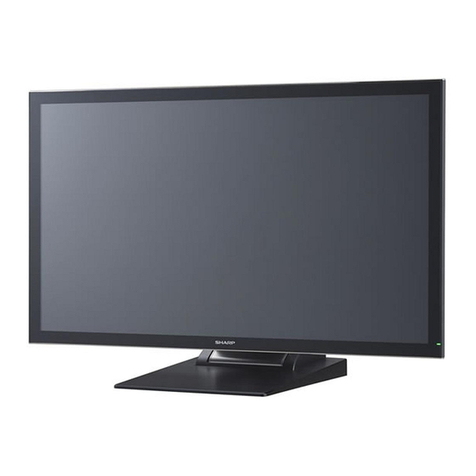
Sharp PN-L803C User manual

SERVICE MANUAL
CODE :00ZPNL803CSME
Parts marked with “!” are important for maintaining the safety of the set. Be sure to replace
these parts with specified ones for maintaining the safety and performance of the set.
This document has been published to be used for
after sales service only.
The contents are subject to change without notice.
SHARP CORPORATION
Model Name Countries
PN-L803C North America
PN-80TC3 Other countries
CHAPTER 1. OUTLINE OF THE PRODUCT············································· 1-1
CHAPTER 2. INSTALLATION, ADJUSTMENT, SETTING, OPERATION 2-1
CHAPTER 3.
INPORTANT INFORMATION FOR SERVICING THE DISPLAY
··· 3-1
CHAPTER 4.
SERVICE MENU/ VARIOUS SETTING TOOL OPERATING PROCEDURES
········ 4-1
CHAPTER 5. FIRMWARE UPDATE PROCEDURES································ 5-1
CHAPTER 6. DISASSEMBLY AND ASSEMBLY······································ 6-1
CHAPTER 7. TOROUBLESHOOTING ······················································ 7-1
CHAPTER 8. HARDWARE DESCRIPTIONS ············································ 8-1
CONTENTS
LCD MONITOR(Touch Display)
/
TOUCH PEN
MODEL
PN-L803C
PN-80TC3
PN-ZL03

CODE :00ZPNY325SM/E
<Solder composition code of lead-free solder>
Solder com
p
osition Solder com
p
osition code
Sn-Ag-Cu a
Sn-Ag-Bi
Sn-Ag-Bi-Cu b
Sn-Zn-Bi z
Sn-In-Ag-Bi i
Sn-Cu-Ni n
Sn-Ag-Sb s
Bi-Sn-Ag-P
Bi-Sn-Ag p
(1) NOTE FOR THE USE OF LEAD-FREE SOLDER THREAD
When repairing a lead-free solder PWB, use lead-free solder thread. Never use conventional lead solder thread, which may cause a
breakdown or an accident.
Since the melting point of lead-free solder thread is about 40°C higher than that of conventional lead solder thread, the use of the exclu-
sive-use soldering iron is recommendable.
(2) NOTE FOR SOLDERING WORK
Since the melting point of lead-free solder is about 220°C, which is about 40°C higher than that of conventional lead solder, and its soldering
capacity is inferior to conventional one, it is apt to keep the soldering iron in contact with the PWB for longer time. This may cause land
separation or may exceed the heat-resistive temperature of components. Use enough care to separate the soldering iron from the PWB when
completion of soldering is confirmed.
Since lead-free solder includes a greater quantity of tin, the iron tip may corrode easily. Turn ON/OFF the soldering iron power frequently.
If different-kind solder remains on the soldering iron tip, it is melted together with lead-free solder. To avoid this, clean the soldering iron tip
after completion of soldering work.
If the soldering iron tip is discolored black during soldering work, clean and file the tip with steel wool or a fine filer.
CAUTIONS
THERE IS A RISK OF EXPLOSION IF THE BATTERY
IS REPLACED BY AN INCORRECT TYPE.
PROPERLY DISPOSE OF USED BATTERIES ACCORDING
TO THE INSTRUCTIONS.
LEAD-FREE SOLDER
The PWB’s of this model employs lead-free solder. The “LF” marks indicated on the PWB’s and the Service Manual mean “Lead-Free” solder.
The alphabet following the LF mark shows the kind of lead-free solder.
CAUTIONS
THERE IS A RISK OF EXPLOSION IF THE BATTERY
IS REPLACED BY AN INCORRECT TYPE.
PROPERLY DISPOSE OF USED BATTERIES ACCORDING
TO THE INSTRUCTIONS.
CAUTION
DOUBLE POLE/NEUTRAL FUSING
ATTENTION.
Double pôle/fusible sur le neutre.

PN-L803C/80TC3 CONTENTS
CONTENTS
CHAPTER 1. OUTLINE OF THE PRODUCTS
1. MAIN FEATURE 1-1
2. SPECIFICATION 1-4
3. PART NAMES AND FUNCTION 1-10
4. SCREEN DISPLAY 1-14
CHAPTER 2. INSTALLATION / SETTINGS
1. INSTALLATION 2-1
2. ADJUSTMENT 2-11
3. OTHER SETTING 2-31
4. TOUCH PEN PREPARATION 2-34
5. TOUCH PANEL PREPARATION 2-36
6. TOUCH ACTION 2-39
CHAPTER 3. IMPORTANT INFORMATION FOR SERVICING THE DISPLAY
1. MAIN PWB, LCD MODULE UNIT, T-CON PWB, TOUCH PANEL UNIT REPLACEMENT
PROCEDURES 3-1
2. TEMPORARY STAND 3-3
CHAPTER 4. SERVICE MENU/VARIOUS SETTING TOOL OPERATING PROCEDURES
1. OPERATING PROCEDURES 4-1
2. AGING 4-2
3. CALIBRATION 4-2
4. FACTORY RESET 4-4
5. HARDWARE CHECK 4-5
6. OTHER FUNCTIONS 4-7
7. INSTRUCTIONS FOR LAUNCHER TOOL 4-12
8. SERIAL NUMBER WRITING PROCEDURES 4-15
9. USAGE TIME SETTING PROCEDURE 4-16
10. MODEL NAME SETTING PROCEDURES 4-17
11. USER SETTING TOOL OPERATION PROCEDURES 4-18
12. OPERATING MANUAL OF THE LOG TOOL 4-20
13. SAVE LOG TO THE USB FLASH DRIVE 4-26
14. WHITE BALANCE SETTING TOOL BY OSD 4-27
15. WHITE BALANCE SETTING TOOL OPERATING PROCEDURE 4-30

PN-L803C/80TC3 CONTENTS
16. GAMMA SETTING PROCEDURES WITH THE OSD 4-32
17. GAMMA SETTING TOOL OPERATION PROCEDURES 4-34
18. TEST PATTERN TOOL 4-36
19. FLICKER ADJUSTMENT TOOL 4-37
20. TOUCH PANEL CALIBRATION TOOL 4-42
21. SENSOR CHECK TOOL 4-44
22. RESET THE ASSIGNED COM PORT NUMBER FOR TOUCH PEN 4-48
23. MAIL DESCRIPTION CONTENT 4-50
24.
CHANGE TOUCH PEN COMMUNICATION CHANNEL(EXTERNAL PC)
4-53
CHAPTER 5. FIRMWARE UPDATE PROCEDURES
1. FIRMWARE UPDATE 5-1
2. HOW TO UPDATE MAIN FIRMWARE VIA NETWORK 5-4
3. HOW TO UPDATE MAIN FIRMWARE VIAUSB FLASH DRIVE 5-6
4. EDID WRITING PROCEDURE 5-10
5. TOUCH PEN, TOUCH PEN ADAPTOR FIRMWARE UPDATE 5-12
CHAPTER 6. DISASSEMBLY AND ASSEMBLY
1. PWB AND WIRNG DIAGRAM 6-1
2. HANDLE 6-2
3. REAR COVER R/ L/C 6-3
4. LED POWER SUPPLY PWB 6-5
5. 5V POWER SUPPLY PWB 6-7
6. AC RELAY PWB 6-8
7. T-CON PWB 6-9
8. AFE PWB 6-10
9. DBE PWB 6-11
10. MAIN PWB 6-12
11. KEY PWB 6-14
12. TOUCH PANEL UNIT 6-16
13. LCD MODULE UNIT 6-20
14. SPEAKER R 6-28
15. SPEAKER L 6-29

PN-L803C/80TC3 CONTENTS
CHAPTER 7. TROUBLESHOOTING
1. THE POWER IS NOT SUPPLIED (THE LED DOES NOT LIGHT UP) 7-1
2. THE REMOTE CONTROL DOES NOT WORK 7-2
3. THE DISPLAY DOES NOT WORK/ DISPLAYABNORMALITY 7-2
4. THE BACKLIGHT DOES NOT LIGHT UP 7-3
5. SOUND IS NOT OUTPUTED/ OUTPUT SOUND ABNORMALITY 7-3
6. DISPLAYPORT(DP) OUTPUT IS NOT MADE /DISPLAYABNORMALITY 7-4
7. CAN NOT CONTROL LAN CONNECTION (LANFORDISPLAY) 7-4
8. THE RED LED FLASHES (DISPLAYABNORMALITYISSET) 7-5
9. THE LED LIGHTS UP IN ORDEROF RED 3 GREEN (TEMPERATURE ERROR)
7-5
10.TOUCHPANELABNORMALITY 7-6
11. TOUCH PEN ABNORMALITY 7-11
CHAPTER 8. HARDWARE DESCRIPTIONS
1. CIRCUIT DESCRIPTIONS 8-1
2. CAPACITANCE TOUCH PANEL THEORY BASIS 8-6
3. BLOCK DIAGRAM 8-7
4. CONNECTOR TABLE 8-18
5. PARTS LAYOUT 8-21

PN-L803C/80TC3 OUTLINE OF THE PRODUCTS 1 - 1
CHAPTER 1 OUTLINE OF THE PRODUCTS
1. MAIN FEATURE
1- 1. Simultaneous Writing for Up to 4 People
- This monitor lets you capture ideas at the moment of creation. Recognising up to 10 touch points, it allows up to four people to write at the
same time with a finger or touch pen. Each pen boasts a thin 3.5 mm tip that makes it easier to add detailed notes that remain legible
when printed out.
Note: Two touch pens are bundled with the monitor.
1 - 2. Featherlight Touch for Precise and Smooth Operation
- Thanks to the monitor’s precise position detection, only intentional input from fingers and touch pens appears on the display. Employing
Sharp’s original capacitive touch technology—which achieves high sensitivity and precision by reducing the noise level to one-eighth that
of conventional models - the monitor eliminates unwanted noise to deliver a clear onscreen signal.
1 - 3. Frontside Access to USB Port
- For increased convenience when the panel is mounted on a wall, this monitor's features a USB input on the front that connects to the
set-top box on the back of the unit. Now there’s no need to reach around the back of the monitor when you want to connect a peripheral
device.
Note: The set-top box is sold separately.

PN-L803C/80TC3 OUTLINE OF THE PRODUCTS 1 - 2
1 - 4. Frontside Access to USB Port
- Sharp Touch Viewer* is a touch-operated onscreen user interface that lets you easily manipulate different types of files, including
Microsoft® Office applications, videos, and web pages. Being able to simultaneously open and handle a variety of file types allows you to
have more active meetings.
* Check with your local Sharp authorised dealer/representative for details on how to obtain this software.
1 - 5. Multi Board Function (Sharp Pen Software)
- Up to three units can be connected and used to display sequential pages that can be navigated by swiping side to side. With the Multi
Board function*, meeting participants are better able to grasp the overall flow of a presentation.
* Requires a compatible version of Sharp Pen Software. Check with your local Sharp authorised dealer/representative for details. Only
one unit can be operated at a time.
1 – 6. Other Value-Adding Functions
- Multiple displays can be wall mounted together
- Safe design incorporating rounded corners
- Thin, lightweight, and fully flat screen
- Built-in speakers
- Anti-glare -lm to minimise reflections
1 – 7. Changes from the current model
Changes PN- L703B PN-L803C
Capacitive touch panel
Operability is improved with high accuracy/high definition display.
Compared with the current model, it is possible to write small 15mm
x 15mm character.
×○
Stylish design with thin-profile
Depth :135mm, Weight : 102 ㎏(PN-L802B) -> Depth : 96mm,
Weight : 80 ㎏
×○
SHARP Touch Viewer ×○
Interface change
HDMIx3, D-subx2, DisplayPorx1 -> HDMIx3, D-subx2,
DisplayPorx1, RS-232Cx1
×○
Settings related with the touch panel have been added. ×○
Power button/Touch menu on the front glass which supports the
capacitive touch panel.
×○

PN-L803C/80TC3 OUTLINE OF THE PRODUCTS 1 - 3
Pen software which supports the multiple installation monitors ×○
The monitor can be rotated 90 degrees counterclockwise from a
landscape installation.
×○
Surface protection glass with AG film ○ ○
The pen tip and the eraser use the material which supports the
capacitive touch panel.
×○
Speakers located at the bottom of the rear side has a cover which
output sound forward.
Front -> Rear bottom
×○
1 – 8. Comparison with the current touch pen
- Pen size is changed for the reduction in size and weight
- Smooth writhing by the pressure sensor
- Personal ID setting by the wireless communication method
- Good operability by the 3 buttons.
- Supports the capacitive touch panel
Name
PN-L603A/ L603B/60TA3/60TB3/
L703A/ L703B/70TA3/70TB3
Touch pen
PN-L803C/80TC3
Touch pen
Image
Communication method Wireless communication method Wireless communication method
Marking on the body No. “CAPACITIVE” is described.
Button 3 buttons 3 buttons
Pen pressure weight 15g 15g
Size Length:140mm
Diameter:20mm
Length:150mm
Diameter:20mm
Pen tip - Supports the capacitive touch panel
Weight 24g(without battery) 26g(without battery)
Wireless communication
method
Pressure sensor
Functional button
Button 1, 2
Small, light
Pen tip supports the capacitive touch panel.

PN-L803C/80TC3 OUTLINE OF THE PRODUCTS 1 - 4
2. SPECIFICATIONS
2 – 1.PRODUCT SPECIFICATIONS
Model PN-L803C/80TC3
LCD component 80" Class [80 inch (203.2cm) diagonal] TFT LCD
Max. resolution (pixels) 1920 x 1080
Max. colors Approx. 1.06 billion colors
Pixel pitch 0.923 mm (H) × 0.923 mm (V)
Viewing angle 176° right/left/up/down (contrast ratio ≥10)
Screen active area inch (mm) 69-3/4 (W) x 39-1/4 (H) (1771.2 x 996.3)
Computer input signal Analog RGB (0.7 Vp-p) [75 Ω], DisplayPort 1.1a
Sync signal Horizontal/vertical separate (TTL: positive/negative),
Sync-on-green*1, Composite sync (TTL:
positive/negative)*1
Video color system NTSC (3.58MHz)/NTSC (4.43MHz)/PAL/PAL-60/SECAM
Plug and play VESA DDC2B
Power management VESA DzPMS
Input terminals PC/AV HDMI x 3
PC Mini D-sub 15 pin, 3 rows x 2, DisplayPort x 1
Audio 3.5 mm mini stereo jack x 2
Serial (RS-232C) 3.5 mm mini jack x 1
Output terminals Video/Audio DisplayPort x 1
Audio 3.5 mm mini stereo jack x 1
LAN terminal 10 BASE-T/100 BASE-TX
Speaker output (internal/external) 10 W + 10 W/10 W + 10 W 6 Ω
Touch Panel Detection method Capacitive type
PC connector USB (2.0 compliant) (Type B) x 2
Touch pen Wireless communication method (2.4 GHz, IEEE 802.15.4
compliant, DS-SS method)
Touch pen adapter port USB (2.0 compliant) (Type A)
Power requirement AC 100 V - 240 V, 2.6 A, 50/60 Hz
Operating temperature *2*3 41°F to 95°F (5°C to 35°C)
Operating humidity*3 20% to 80% (no condensation)
Power consumption
(Maximum / input signal waiting mode *4 / whiteboard standby mode / standby mode *5)
280 W / 6.0 W / 3.5 W
Dimensions (excluding protrusions) inch(mm) Approx. 72-13/16 (W) x 3-3/4 (D) x 42-3/16 (H) (1850 x 96 x
1072)
Weight lbs. (kg) Approx. 169.8 (77)
*1 D-sub input terminal only.
*2 Temperature condition may change when using the monitor together with the optional equipments recommended by SHARP.
In such cases, please check the temperature condition specified by the optional equipments.
*3 In addition, check the requirements of the computer and other devices to be connected, and make sure that all requirements are
satisfied.
*4 When CONNECT AUTO INPUT SELECT and NO SIGNAL AUTO INPUT SEL. are set to OFF.
*5 When STANDBY MODE is set to STANDARD. When STANDBY MODE is set to LOW POWER: 0.5 W
As a part of our policy of continuous improvement, SHARP reserves the right to make design and specification changes for product
improvement without prior notice. The performance specification figures indicated are nominal values of production units. There may be
some deviations from these values in individual units.

PN-L803C/80TC3 OUTLINE OF THE PRODUCTS 1 - 5
2 – 2.DIMENSIONAL DRAWINGS (THE VALUES SHOWN ARE APPROXIMATE VALUES)
When mounting the monitor, be sure to use a wall-mount bracket that complies with the VESA-compatible mounting method.
SHARP recommends using M6 screws and tighten the screws.
Note that screw hole depth of the monitor is 3/8 inch (10 mm). Loose mounting may cause the product to fall, resulting in
serious personal injuries as well as damage to the product. The screw and hole should come together with over 5/16 inch
(8 mm) length of thread. Use a bracket which has been approved for UL1678 standard, and which can endure at least 4 times
or more the weight of the monitor.

PN-L803C/80TC3 OUTLINE OF THE PRODUCTS 1 - 6
2 – 3.COMPATIBLE SIGNAL TIMING (PC)
Screen resolution Hsync Vsync Dot
frequency
Digital Analog
(D-SUB)
Display
Port HDMI
VESA
640×480
31.5khz 60Hz 25.175MHz Yes Yes Yes
37.9kHz 72Hz 31.5MHz Yes Yes Yes
37.5kHz 75Hz 31.5MHz Yes Yes Yes
800×600
35.1kHz 56Hz 36.0MHz - - Yes
37.9kHz 60Hz 40.0MHz Yes Yes Yes
48.1kHz 72Hz 50.0MHz Yes Yes Yes
46.9kHz 75Hz 49.5MHz Yes Yes Yes
848×480 31.0kHz 60Hz 33.75MHz - - Yes
1024×768
48.4kHz 60Hz 65.0MHz Yes Yes Yes
56.5kHz 70Hz 75.0MHz Yes Yes Yes
60.0kHz 75Hz 78.75MHz Yes Yes Yes
1152×864 67.5kHz 75Hz 108.0MHz Yes Yes Yes
1280×768 47.8kHz 60Hz 79.5MHz Yes - Yes
60.3kHz 75Hz 102.25MHz Yes - Yes
1280×800 49.7kHz 60Hz 83.5MHz Yes Yes Yes
1280×960 60.0kHz 60Hz 108.0MHz Yes Yes Yes
1280×1024 64.0kHz 60Hz 108.0MHz Yes Yes Yes
80.0kHz 75Hz 135.0MHz Yes Yes Yes
1360x768 47.7kHz 60Hz 85.5MHz Yes Yes Yes
1400×1050 65.3kHz 60Hz 121.75MHz Yes Yes Yes
1440×900 55.9kHz 60Hz 106.5MHz Yes Yes Yes
1600×1200* 75.0kHz 60Hz 162.0MHz Yes Yes Yes
1680×1050 65.3kHz 60Hz 146.25MHz Yes Yes Yes
1920×1200* 74.0kHz 60Hz 154.0MHz Yes Yes Yes
Wide 1280×720 44.7kHz 60Hz 74.4MHz Yes Yes Yes
1920×1080 67.5kHz 60Hz 148.5MHz Yes Yes Yes
US TEXT 720×400 31.5kHz 70Hz 28.3MHz Yes Yes Yes
Sun
1024×768
48.3kHz 60Hz 64.13MHz - - Yes
53.6kHz 66Hz 70.4MHz - - Yes
56.6kHz 70Hz 74.25MHz - - Yes
1152×900 61.8kHz 66Hz 94.88MHz - - Yes
71.8kHz 76.2Hz 108.23MHz - - Yes
1280×1024 71.7kHz 67.2Hz 117.01MHz - - Yes
81.1kHz 76Hz 134.99MHz - - Yes
1600×1000 68.6kHz 66Hz 135.76MHz --Yes
* Displays a reduced image, except in Dot by Dot. In Dot by Dot, the image will be cut down to panel size then displayed.
* Depending on the connected PC, images may not be displayed properly even if the compatible signal described above is input.
* The frequency values for the Sun are reference values.

PN-L803C/80TC3 OUTLINE OF THE PRODUCTS 1 - 7
2 – 4. COMPATIBLE SIGNAL TIMING (AV)
Screen resolution Frequency HDMI Component
1920 × 1080p 24Hz Yes -
50Hz Yes Yes
59.94Hz Yes Yes
60Hz Yes Yes
1920 × 1080i 50Hz Yes Yes
59.94Hz Yes Yes
60Hz Yes Yes
1280 × 720p 50HZ Yes Yes
59.94Hz Yes Yes
60Hz Yes Yes
720 × 576p 50Hz Yes Yes
720 × 480p 59.94Hz Yes Yes
60Hz Yes Yes
640 × 480p(VGA) 59.94Hz Yes -
60Hz Yes -
720(1440) × 576i 50Hz Yes Yes
720(1440) × 480i 59.94Hz Yes Yes
60Hz Yes Yes
2 – 5.POWER MANAGEMENT
This monitor conforms to VESA DPMS. Both your video card and computer must support the same standard in
order for the monitor’s power management function to work.
DPMS:Display Power Management Signaling
DPMS Screen Power consumption *1 Hsync Vsync
ON STATE Display 280 W Yes Yes
STANDBY
No
display 6.0 W *2
No Yes
SUSPEND Yes No
OFF STATE No No
* When CONNECT AUTO INPUT SELECT and NO SIGNAL AUTO INPUT SEL. are set to OFF.
2 – 6.DDC (PLUG AND PLAY)
The monitor supports the VESA DDC (Display Data Channel) standard.
DDC is a signal standard for plug and play between monitors and computers. Information about resolution and other parameters
is exchanged between the two. This function can be used if the computer supports DDC and it has been configured to detect
plug-and-play monitors.
There are several types of DDC, depending on the communication method used. This monitor supports DDC2B.

PN-L803C/80TC3 OUTLINE OF THE PRODUCTS 1 - 8
2 – 7.LAYOUT OF TERMINAL PINS
■ D-sub input terminal pins
(Mini D-sub 15 pin)
No. Function No. Function
1 Red video signal input 9 +5V
2 Green video signal input 10 GND
3 Blue video signal input 11 N.C.
4 N.C. 12 DDC data
5 GND 13 Hsync signal input
6 GND for red video signal 14 Vsync signal input
7 GND for green video signal 15 DDC clock
8 GND for blue video signal
■ HDMI input terminal pins
(HDMITM Connector)
No. Function No. Function
1 TMDS data 2+ 11 TMDS clock shield
2 TMDS data 2 shield 12 TMDS clock-
3 TMDS data 2- 13 CEC
4 TMDS data 1+ 14 N.C.
5 TMDS data 1 shield 15 SCL
6 TMDS data 1- 16 SDA
7 TMDS data 0+ 17 DDC/CEC GND
8 TMDS data 0 shield 18 +5V
9 TMDS data 0- 19 Hot-plug detection
10 TMDS clock+
■ DisplayPort input terminal pins
(DisplayPort 20 pin)
No. Function No. Function
1 MainLane 3- 11 Gnd
2 Gnd 12 MainLane 0+
3 MainLane 3+ 13 Gnd
4 MainLane 2- 14 Gnd
5 Gnd 15 Aux +
6 MainLane 2+ 16 Gnd
7 MainLane 1- 17 Aux -
8 Gnd 18 Hot-plug detection
9 MainLane 1+ 19 Gnd
10 MainLane 0- 20 3.3V
■ DisplayPort output terminal pins
(DisplayPort 20 pin)
No. Function No. Function
1 MainLane 0+ 11 Gnd
2 Gnd 12 MainLane 3-
3 MainLane 0- 13 Gnd
4 MainLane 1+ 14 Gnd
5 Gnd 15 Aux +
6 MainLane 1- 16 Gnd
7 MainLane 2+ 17 Aux -
8 Gnd 18 Hot-plug detection
9 MainLane 2- 19 Gnd
10 MainLane 3+ 20 3.3V

PN-L803C/80TC3 OUTLINE OF THE PRODUCTS 1 - 9
2 – 8. SUPPLIED COMPONENTS
Liquid Crystal Display Monitor: 1
Remote control unit: 1 Cable clamp: 3
Cable clamp (insertion type): 4
* Sharp Corporation holds authorship rights to the Utility Disk program. Do not reproduce it without permission.
* For environmental protection!
Do not dispose of batteries in household waste. Follow the disposal instructions for your area.
2 – 9 SYSTEM REQUIREMENT
To use the touch panel, the touch panel and computer must be connected, and Touch Panel Settings Tool, Touch Pen Utility, and
Pen Software must be installed on the computer from the supplied CD-ROM.
When the Touch Display Downloader is installed, you can check and download the most recent versions of the software programs. To
install the software, see the manual for each.
The USB port varies depending on the terminal connected to the computer.
(Factory setting. Can be changed in TOUCH INPUT SELECT in the SETUP menu.)
Download the setup program for the Touch Viewer with the Touch Display Downloader.
Power cord: 1
Remote control unit battery (R-6 (“AA” size)): 2
CD-ROM (Utility Disk): 1
CD-ROM (Touch Display Link): 1
Touch Display Link License: 1
Setup Manual: 1
Touch pen (for capacitive touch panel PN-ZL03): 2
Touch pen adapter (PN-ZL03): 1
Pen tip for touch pen (for capacitive touch panel): 4
Touch pen battery (LR-03 (“AAA” size)): 2
Tray: 1
Speaker cover: 2
USB cable: 1
RS-232C conversion cable (3.5mm mini jack): 1
Eraser (for capacitive touch panel): 1
Camera mount: 1
Camera screw (inch thread): 1
Touch pen adapter screw (Step screw, M3): 1
Speaker cover attachment screws (M3)/ Camera mount screws
(M3): 6
Vertical sticker (Logo): 1
ID labels (for touch pen): 4 x 2
Cover Sharp logo: 1
Place this sticker onto the SHARP logo to cover the logo.

PN-L803C/80TC3 OUTLINE OF THE PRODUCTS 1 - 10
3. PART NAMES AND FUNCTION
3 - 1.DISPLAY
■Front view
(
State the power light is lit)
LED state Monitor state PN-L703B PN-L803C
Turn OFF Main power OFF ○ ○
Orange lights up Power standby ○ ○
Green lights up Main power ON ○ ○
Green -> Turn OFF ->
(1sec. interval)
Signal standby ○○
Orange -> Red ->
(1sec. interval)
Power standby (Setting the schedule) ○○
Green -> Turn OFF ->
(0.5sec. interval)
Power ON delay ○○
Red -> Turn OFF ->
(1sec. interval)
Hardware error occurs ○○
Red -> Green ->
(1sec. interval)
Hardware error occurs ○○
When switching the main power switch or the POWER button off and back on, always wait for at least 5 seconds. A short interval may
result in a malfunction.
1 Remote control sensor
2 Power LED
3 Power button
4 TOUCH MENU button
5 USB port (for USB device) (USB 2.0
compliant)
6Tray
7 Speakers
8 Handles2

PN-L803C/80TC3 OUTLINE OF THE PRODUCTS 1 - 11
■Rear view
9 Vents 17 USB 1 port 25 Terminal for firmware updating
10 Optional attachment section 18 LAN terminal 26 USB 2 port (for touch panel)
11 Main power switch 19 Optional terminal 27 D-sub 2 input terminal
12 AC input terminal 20 D-sub 1 input terminal 28 HDMI 2 input terminal
13 External speaker terminals 21 DisplayPort input terminal 29 HDMI 3 input terminal
14 Audio output terminal 22 HDMI 1 input terminal 30 Audio 2 input terminal
15 DisplayPort output terminal 23 Audio 1 input terminal 31 USB ports
16 Touch pen adapter port 24 RS-232C input terminal

PN-L803C/80TC3 OUTLINE OF THE PRODUCTS 1 - 12
3- 2. REMOTE CONTROL UNIT
No. Function Contents
1 Signal transmitter
2 POWER button
3 MUTE
button
Turns off the volume temporarily.
Press the MUTE button again to turn the sound back
to the previous level.
4
VOL +/-
buttons
Pressing or displays the VOLUME menu
when the menu screen is not displayed.
Press or to adjust the volume of the sound.
* If you do not press any buttons for about 4
seconds, the VOLUME menu automatically
disappears.
* You can also change the setting by touch action.
BRIGHT
+/-
buttons
Pressing or displays the BRIGHT menu
when the menu screen is not displayed.
Press or to adjust the brightness.
* If you do not press any buttons for about 4
seconds, the BRIGHT menu automatically
disappears.
Cursorcontrol( / / / )buttons
5 DISPLAY
button
Displays monitor information.
The display changes from INFORMATION1 ->
INFORMATION2 -> clear display, and so on every
time you press this button.
- The display disappears automatically after about 15
seconds.
- is displayed during LAN communication.
- If is displayed in red, there is a duplicate IP
address.
6 MODE
button
Each time you press this button, the color mode
changes in the following order:
- sRGB applies to PC input only.
sRGB is international standard of color
representation specified by IEC (International
Electrotechnical Commission). Color conversion is
made in taking account of liquid crystal’s
characteristics and represents color tone close to its
original image.
- HIGH ILLUMINANCE is a display with colors suited
to bright locations.
7 INPUT
button
The menu is displayed. Press or to select the
input mode, and press to enter.
TOUCH menu on the monitor button can change the
input mode.
- When the input mode is changed, the touch panel
connection also changes. You can set whether the
side or bottom USB port is used in each input mode.
*1 Select the terminal to be used in HDMI1 of INPUT
SELECT.
*2 Select the terminal to be used in HDMI2 of INPUT
SELECT.
*3 Select the terminal to be used in HDMI3 of INPUT
SELECT.
*4 Select the terminal to be used in D-SUB1 of
INPUT SELECT.
*5 Select the terminal for AUDIO SELECT which is
used for audio input.
Input mode Video Audio
DisplayPort DisplayPort input
terminal
*5
HDMI1 HDMI1 input
terminal*1
HDMI2 HDMI2 input
terminal*2
HDMI3 HDMI3 input
terminal*3
D-SUB1 D-sub1 input
terminal*4
D-SUB2 D-sub2 input terminal
8 MENU
button
Displays and turns off the menu screen.
9 ENTER
button
Confirms the setting.
10 RETURN
button
Returns to the previous screen.
11 SIZE
button
The menu is displayed.
Press or to select the screen size.

PN-L803C/80TC3 OUTLINE OF THE PRODUCTS 1 - 13
■Installing the batteries
1) Press the cover gently and slide it in the direction of the arrow.
2) S See the instructions in the compartment and put in the
supplied batteries (R-6 (“AA” size) x 2) with their plus (+) and
minus (-) sides oriented correctly.
3) Close the cover.
(MEMO)
• When the batteries become exhausted, replace them with new
(commercially available) batteries.
•The supplied batteries (R-6 (“AA” size) x 2) may become
exhausted quickly depending on how they are stored.
• If you will not be using the remote control for a long time, remove
the batteries.
• Use manganese or alkaline batteries only.
■Remote control operation ranges
The operation range of the remote control unit is approx. 16.4 feet
(5 m) at an angle of approx 10° from the center to the top
/bottom/right/left of the remote control sensor.
(MEMO)
• Do not expose the remote control unit to shock by dropping or
stepping on it. This could lead to a malfunction.• Do not expose
the remote control unit to liquids, and do not place it in an area
with high humidity
• The remote control unit may not work properly if the remote
control sensor is under direct sunlight or strong lighting.
• Objects between the remote control unit and the remote control
sensor may prevent proper operation.
• Replace the batteries when they run low as this may shorten the
remote control’s operation range.
• If a fluorescet light is illuminated near the remote control unit, it
may interfere with proper operation.
• Do not use it with the remote control of other equipment such as
air conditioner, stereo components, etc.

PN-L803C/80TC3 OUTLINE OF THE PRODUCTS 1 - 14
4. SCREEN DISPLAY
4 – 1.DUAL SCREEN DISPLAY
It is possible to display two screens simultaneously.
Set this function with “PIP MODES” in the PIP/PbyP menu.
* The currently selected input signal is displayed on the main screen.
* The following combinations are available for display:
DisplayPort - D-SUB1, D-SUB2
HDMI1, HDMI2, HDMI3 - D-SUB1, D-SUB2
PIP A sub screen is displayed inside a main screen.
PbyP A main screen and a sub screen are displayed in a line.
PbyP2 Displays a main screen which measures 1280 pixels in the longest
direction and a sub screen in a line.
(MEMO)
• You might infringe on a copyright of the author which is protected by copyright law when you display the images of the computer screen
and television/VCR simultaneously for profit-making or to show the image to the public.
• The screen size for dual-screen display is the same as the screen size for single-screen display. The Dot by Dot screen is displayed in
NORMAL size except when it is set as the PIP main screen.
• When dual-screen display is selected, the SCREEN MOTION function is disabled.
• When dual-screen display is selected, the CONNECT AUTO INPUT SELECT function and NO SIGNAL AUTO INPUT SEL. function are
disabled.
• When dual-screen display is selected, the INPUT SELECT options cannot be set.
• When dual-screen display is selected, the AUDIO menu cannot be set.
• When an interlaced signal (1080i, 480i, video) is input to the sub screen, horizontal lines may flicker. If this happens, display the image
on the main screen.
• Touch operation cannot be used in the sub screen.

PN-L803C/80TC3 OUTLINE OF THE PRODUCTS 1 - 15
4 – 2.SWITCHING THE SCREEN SIZE
Even when the screen size is changed, the display may remain the same depending on the input signal.
WIDE PC input Displays image so it fills the entire screen.
AV input An image with a 4:3 aspect ratio is stretched to fill the entire screen.
ZOOM 1 PC input An image with a 4:3 aspect ratio is enlarged to fill the entire screen without changing
the aspect ratio. The edges of the image may be cut off.
AV input
ZOOM 2 PC input Use this size if ZOOM 1 cuts off the subtitles.
AV input
NORMAL PC input Displays image so it fills the screen without changing the aspect ratio of the input
signals.
AV input Displays the entire image of the aspect ratio of 4:3 without changing the aspect ratio.
Dot by Dot PC input Displays the dots of the signals input from the connected PC as the corresponding
dots on the screen.
AV input Displays the dots of the input signals as the corresponding dots on the screen.
(MEMO)
• Using this monitor’s screen-size switching or dual-screen display functions to compress or expand the screen for commercial
or public viewing in establishments like cafes or hotels may infringe on the rights of the creators, as protected by Copyright
Law, so please be careful.
• When dual-screen display is selected, the screen size cannot be changed.
• The appearance of the original video may change if you select a screen size with a different aspect ratio than the original
image (e.g. TV broadcast or video input from external equipment).
• When an ordinary non-wide image (4:3) is viewed with the whole screen using the screen-size switching function of this
monitor, the edge of the image may be lost or appear distorted. If you wish to respect the creator’s intentions, set the screen
size to “NORMAL”.
• When playing commercial software, parts of the image (like subtitles) may be cropped. In this case select the optimal screen
size using the screen-size switching function of this monitor. With some software, there may be noise or distortion at the
edges of the screen. This is due to the characteristics of the software, and is not a malfunction.
• Depending on the original image size, black bands may remain at the edges of the screen.
Other manuals for PN-L803C
3
This manual suits for next models
2
Table of contents
Other Sharp Monitor manuals

Sharp
Sharp LL-173C User manual

Sharp
Sharp 8M-B120C User manual

Sharp
Sharp PN-80SC5 User manual

Sharp
Sharp PN-70TA3 User manual

Sharp
Sharp LL-173C Guide

Sharp
Sharp 8M-B80AX1E User manual

Sharp
Sharp PN-L603W User manual

Sharp
Sharp PN-465E User manual

Sharp
Sharp PN-L803CA User guide

Sharp
Sharp LL-T1512W User manual

Sharp
Sharp LL-T17A3 User manual

Sharp
Sharp PN-HB851 Instruction sheet

Sharp
Sharp PN-L705H User manual

Sharp
Sharp PN-E702 User guide

Sharp
Sharp PN-425 User manual

Sharp
Sharp TL-M5200 User guide

Sharp
Sharp LL-171A User manual

Sharp
Sharp PN-Q901 User manual

Sharp
Sharp LL-T15A3 User manual

Sharp
Sharp PN-L851H User manual