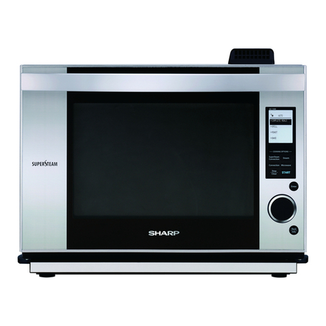
Sharp SuperSteam Plus SSC3088AS User manual

SSC3088AS
1
In the interest of user-safety the oven should be restored to its original condition and only parts identical to those specified should
be used.
WARNINGTO SERVICE PERSONNEL:Ovens contain circuitry capable of producing very high voltage and current.Contact
with the following parts may result in a severe, possibly fatal, electrical shock.
TABLE OF CONTENTS
Page
PRECAUTIONS TO BE OBSERVED BEFORE AND DURING SERVICING.........................................................2
BEFORE SERVICING............................................................................................................................................2
WARNING TO SERVICE PERSONNEL.................................................................................................................2
FOREWORD AND WARNING ...............................................................................................................................3
PRODUCT SPECIFICATIONS...............................................................................................................................4
OVEN COMPONENTS...........................................................................................................................................5
CONTROL PANEL..................................................................................................................................................6
SCHEMATIC...........................................................................................................................................................7
SUPER STEAM COMPONENTS...........................................................................................................................9
TEST PROCEDURES..........................................................................................................................................15
HOW TO REPLACE MAIN PARTS.......................................................................................................................24
PARTS LIST ........................................................................................................................................................40
PACKING AND ACCESSORIES ..........................................................................................................................60
SY5M387SSC308
SUPER STEAM PLUS
OVEN
SERVICE MANUAL
SSC3088AS
START
CLEAR
MANUAL BACK
This document has been published to be used for after sales service only. The contents are subject to change without notice.
SHARP ELECTRONICS OF CANADA LTD.
335 Britannia Road East, Mississauga, Ontario L4Z 1W9
(905) 568-7140
Website: www.sharp.ca

SSC3088AS
2
PRECAUTIONSTO BE OBSERVED BEFORE AND
DURING SERVICING
(a) Do not operate or allow the oven to be operated with the door open.
(b) Make the following safety checks on all ovens to be serviced before and/or makeing repairs as nec-
essary: (1) interlock operation, (2) proper door closing, (3) seal and sealing surfaces (wear, and other
damage), (4) damage to or loosening of hinges and latches, (5) evidence of dropping or abuse.
(c) Any defective or misadjusted components in the interlock, monitor, door seal, and transmission sys-
tems shall be repaired, replaced, or adjusted by procedures described in this manual before the oven is
released to the owner.
WARNINGTO SERVICE PERSONNEL
Steamovenscontaincircuitrycapableofproducing
very high voltage and current, contact with follow-
ing parts
may result in a severe, possibly fatal,
electrical shock.
Read the Service Manual carefully and follow all
instructions.
Don't Touch !
Danger High Voltage
GROUNDING INSTRUCTIONS
This appliance must be grounded.The oven is
equipped with a cord having a grounding wire with a
grounding plug.It must be plugged into a wall
receptacle that is properly installed and grounded in
accordance with the National Electrical Code
and local codes and ordinances.In the event of an electrical
short circuit, grounding reduces risk of electric shock by
providing an escape wire for the electric current.
– Improper use of the grounding plug can
result in a risk of electric shock. Do not use an extension
cord. If the power supply cord is too short, have a
qualified electrician or serviceman install an outlet near
the appliance.
3-Pronged
Plug
Grounded
Receptacle Box
Grounding Pin
3-Pronged Receptacle

SSC3088AS
3
SHARP ELECTRONICS OF CANADA LTD.
335 Britannia Road East, Mississauga, Ontario L4Z 1W9
(905) 568-7140
Website: www.sharp.ca
SERVICE MANUAL
SuperSteam Plus Oven
SSC3088AS
FOREWORD
This Manual has been prepared to provide Sharp Electronics Corp.
Service Personnel and Service Information for the SUPERSTEAM
PLUS OVEN.
It is recommended that service personnel carefully study the entire
text of this manual so that they will be qualified to render satisfactory
customer service.
Check the interlock switches and the door seal carefully. Special at-
tention should be given to avoid electrical shock hazard.
WARNING
Never operate the oven until the following points are ensured.
(A) The door is tightly closed.
(B) The door brackets and hinges are not defective.
(C) The door packing is not damaged.
(D) The door is not deformed or warped.
(E) There is not any other visible damage with the oven.
Servicing and repair work must be carried out only by trained service
personnel. DANGER
Certaininitialpartsareintentionallynotgroundedandpresent
a risk of electrical shock only during servicing.
PRODUCT DESCRIPTION
SCHEMATICS
TEST PROCEDURE
MICROWAVE DRAWER
DISSASSEMBLY AND
ADJUSTMENT PROCEDURE
WIRING DIAGRAM
PARTS LIST

SSC3088AS
4
SPECIFICATION
ITEM DESCRIPTION
Power Requirements 120 Volts
12.04 Amperes
60 Hertz / Single phase, 3 wire grounded
Power Output Top Heater - 750 Watts
Mid Heater - 600 Watts
Rear Heater - 400 Watts
Engine Heater - 1350 Watts
Convection Power Output 1450 Watts
Outside Dimensions Width 30" Height 19.0" Depth 18.92" (with handle)
Cooking Cavity Dimensions
(1.1 Cubic Feet ) (Stainless Steel) Width 15.55" Height 9.45" Depth 12.1"
Control Complement Heating modes:
Super Steam
Convection
Steam
Grill/Broil
Home Page:
Healthy Meals, Smart Cook, Healthy Desserts, Steam Defrost, Meatless
Meals, Steam Options, Settings and Clean.
Manual Page:
Conv Bake, Conv Broil, Steam Roast, Steam Grill, Stea, and Steam Refresh.
Settings:
Manual, Back, Clear and Start
Oven Cavity Light Yes
Safety Standard UL Listed
Canadian Standards Association.

SSC3088AS
5
OVEN COMPONENTS
19
20
1
8
7
6
2
3
4
5
1 Air vent opening
2 Handle
3 LCD display
4 Control panel
5 Frame
6 Drip tray (see page 11)
7 Reservoir lid (see page 11)
8 Reservoir (see page 11)
9 Oven light
10 Anti-tip stubs
11 Tray guide
12 Upper level
13 Lower level
14 Door hinges
15 Latches
16
17
18 Door gasket
ACCESSORIES
19 2 Trays
20 2 Racks
1817
9
14
16
11
10
12
13
15

SSC3088AS
6
HOME PAGE MANUAL PAGE
CONTROL

SSC3088AS
7
SCHEMATIC
CNB
FM PMDM
OLDMDM
EH
DAMPER MOTOR
(Intake)
DAMPER MOTOR
(Exhaust)
OVEN LAMP
FAN MOTOR
DAMPER MOTOR
(SH)
PUMP MOTOR
(CCW)
PUMP MOTOR
(CW)
CNE
#5 CNE
#3 CNE
#4 CNE
#2 CNE
#1 CNE
#6 CNF
#2 CNF
#1
“F”
E11 “C”
E5 “D”
E7 “B”
E3 “E”
E9 “G”
E13 “H”
F3 “J”
F1
B28 B32
2
(GRD) 1
(+24)
1
(L) 3
(N)
ENGINE HEATER
(STEAM)
SH HEATER
(UPPER)
SH HEATER
(CENTER)
SH HEATER
(LOWER)
B14 B16
ENGINE
WATER
LEVEL
SENSOR
LCOM
B9 B10
B7
THERMISTOR
(ENGINE)
THERMISTOR
(OVEN)
B28
B28
JM
SM
B15
CW/CCW
CNE IN-BOARD
HARNESS PIN# CNF IN-BOARD
HARNESS PIN#
B19
PWM
B21
24V
B17
GND
CIRCULATION
MOTOR
1
3
5
4
B13
SM
B11
11 22
SIROCCO MOTOR
(RIGHT)
SIROCCO MOTOR
(LEFT)
(OVEN UNDERSIDE )
N H
C10
CHASSIS
GND
20A
FUSE
(GND ON
UNDERSIDE
OF UNIT)
CHASSIS
GND
“TO SOURCE”
470 Ω1/2W
1.0uF 275V (LINE ACROSS)
NOISE SUPPRESSION COIL
2pc: 0.0033uF 250V (LINE BYPASS)
“TO SOURCE”
120Vac 60Hz
WR
2 2
GND
FM 12V
1 1
(INSIDE DOOR)
CAVITY
THERMO
CUT-OUT
LATCH SWITCH
ENGINE
THERMO
CUT-OUT
FAN
THERMO
CUT-OUT
RY7
RY8
RY6
RY9
RY12
RY11
RY10
B25
TANK SWITCH
B8
DAMPER SWITCH
(SH)
B27
DAMPER SWITCH
(Exhaust)
B26
DAMPER SWITCH
(Intake)
B23
DEW TRAY
SWITCH
B31
DOOR SENSING
SWITCH
B28
CHASSIS
GND
(GND ON
UNDERSIDE
OF UNIT)
L
N
LN
CN101
CN201
DM1
DM2
AC5OL PM1
DM3
FM CNB
PM2 AC4 COOK AC3 SH1 AC3 SH3
AC3 SH2 AC3
CNP
20 pin
Connector
WHQ
RY1RY2RY3 RY4 RY5
Power Unit

SSC3088AS
8
Always take caution lifting heavy products.
3. Use a minimum of 2 people to lift and remove oven.
Partially remove oven from cabinet and unplug the power
supply cord from the electrical outlet (Figure 7).
4. When removing the unit, careful not to use the outer
oven frame. Use only the Side Handles (Figure 7).
DO NOT
lift this unit
using the outer
oven frame
Side Handle (x2)
Lift point
on frame
Figure 7
2. Opentheovendoorandremovethe4mountingscrewsfrom
the Mounting Bracket (Figure 6).
Figure 6
1. Openthedriptraydoorandremovethe2shoulder
Figure 5
bolts/sleeve (Figure 5).
Figure 8
5. Remove 4 screws (2 each side) from the BIK Mount.
After the BIK Mount is removed, careful not to scratch
or damage (Figure 8).
BIK Mount
Screws
SUPER STEAM REMOVAL FROM CABINET

SSC3088AS
9
SUPER STEAM COMPONENTS
[1] Wiring method of each part
● Latch SWK
●
Oven lamp
●
D Motor (exhaust)
Red/black
Yellow
(rear plate side)
(main harness)
D motor
(exhaust)
●
Damper SW (exhaust)
White/white (COM.)
(controlling harness)
Damper SW (exhaust)
Black (N.C.) (outside)
● D Motor (Intake), Damper SW (Intake)
D motor
Damper SW (COM): White/white
(controlling harness)
Gray
(main harness)
Black (upper side)
(main harness)
Damper SW (NO.) (upper side):
Red (controlling harness)
●Harness to D Motor, Damper SW
Upper Air supply
duct cover
Damper SW
Hook
D motor (intake)
Door SW
Main latch SW
Black/Black (COM.)
Black (COM.)
Black (NO.)
Controlling
harness
Main
harness
Red (NO.)
Red/brown
(main harness)
Oven
lamp
Blue (oven side)
(main harness)
Red/brown
(main harness)
Oven
lamp
Blue (oven side)
(main harness)
Red/brown
(main harness)
Oven
lamp
Blue (oven side)
(main harness)

SSC3088AS
10
●SH Heater (lower), Engine liquid-level sensor , Thermistor
(oven)
SF heater (lower)
engine unit side:
Red (main harness)
SH heater (lower):
Blue (main harness)
Thermistor
harness
(oven)
Controlling harness
connector (blue case)
Engine unit
Engine water level sensor
(heater side): White
(controlling harness)
Engine water level sensor:
Blue (controlling harness)
●
E Heater, Engine thermo
E heater (rear plate side):
Blue/white (main harness)
Engine
unit
E heater
(oven side):
Brown (main harness)
Engine motor: White
(main harness)
●Sirocco motor (left)
Harness of the
sirocco motor (left)
Sirocco motor (left)
Controlling harness connector (white case)
●
Sirocco motor (right)
Thermistor
(engine)
harness
Connector
(blue case)
Controlling
harness
Sirocco
motor (right)
Controlling harness
Connector (white case)
Harness of sirocco
motor (right)

SSC3088AS
11
Blue
(Housing)
AC cord
Red
HN
●
Wiring on the right side
Controlling harness
Main harness
D motor
(exhaust)
Main latch SW
Oven lamp
Door SW
●
Backside wiring
Engine
unit
Sirocco motor (left)
Circulation unit K
D motor (exhaust)
D Motor (intake)
●
Tank SW, and pump motor
Bottom plate
White/white (COM.)
Tank SW
Brown (NC.)
Pump motor connector
Main harness
connector
● Fan motor
Fan motor
Controlling harness
Snap-on fastening position
Fan duct cover
Black/black
(main harness)
White (main harness)
● Drip pan SW
White/white (COM.)
(Controlling harness)
SW holder (There is a
drip pan SW inside it.)
Orange (NC.)
(controlling harness)
● AC code

SSC3088AS
12
NOISE FILTER
RED (SOURCE)
BLUE (SOURCE)
WHITE (LOAD)
BLACK (LOAD)
20A FUSE

SSC3088AS
13
●
(Main harness)
CN-B (controlling harness)
(Main harness)
(Controlling harness)
Door
side
Rear
plate
side
CN-P
(Controlling harness)
Red BLU
Black
1
2
White
4
White
6
White
8
White
10
Black
3
Black
5
Black
7
Black
9
White/blue (white case)
white/white
Red
White
11
12
White
13
14
1
5
White
7
Black
9
Red
11
Orange
13
Gray
15
Black
17
Red
19
Black
21
Orange
23 25
3
2
6
8
Yellow
10
Brown
12
14
Blue
16
White
18
20
22
24
26
Red
Black
27 29
Red
31
28
White
30
324
Black/red (white case)
Red/red (red case)
Black/black (blue case)
Black (black case)
Black
Brown
J H
BLK RED BLU GRN
G F
GRY BLK
BRN YLW
E D
WHT YLW
ORG RED
C B
GRY BLU
Blue
RY5
MOLEX
MOLEX
Black
RY4 RY3 RY2 RY1
Connection of door assembly
Wiring protection cover
Controlling harness
Door
assembly
Display board
harness connector
Note: Do not reversely insert the connector of the controlling
harness and the connector of the display board harness
when connecting them.
BLK
BLU
1
2
3
CN-101
BLK
WHT
1
2
CN-201
POWER UNIT
CONTROL UNIT
Power unit check:
While oven is power and idle:
1) CN101: Do you have AC-120V across
pins #1 and #3?
• No – check AC side of harness feeding into
Sw. Unit
2) Yes then check CN201: Do you have
DC-24VDC across pin#1 and pin #2?
• No – replace large Sw. Unit
3) Yes then check Control Unit CN-B:
Do you have DC-24VDC across pins
#28 & #32?
• No – check DC side of harness feeding
from Large Sw. Unit into Control Unit
• Yes – check/replace control unit.

SSC3088AS
14
Error Code list
error display
(EEPROM)
detailsof error check timing application menu error conditionnote check item changeparts
CODE(04)oven temperature
is high.After 1sec.
fermentation
defrost
sterilization
low temp. steam
oven temperature is too
high
fermentation mode
over ECh bit error
under C0h bit cancel
1.Check the relay welding
2.Check the oven thermistor
3.Check the harness of the CN-B and
thermistor
1.Change the relay board
2.Chenge the oven thermistor
3.Change the control harness
CODE(0A) shortage of Water immediately steam
water oven
water grill
Water tank is empty when
water is necessary to
operate.
In the case of water shortage even though
there is water in the water tank.
Check water.
1.When there is no water :change the
pump。
2.When the pump is OK:change the engine
CODE(07)
shortage of Water
(It is possible to
restart)
After cooksterilization Water tank is empty during
sterilization mode.
CODE(08)
shortage of Water
(sterillization
mode restarts)
After cooksterilization 4 minutes passed without
restart after (CODE07)"
appeared.
CODE(0F) water tank is
frozen immediately steam
water oven
water grill
engine heater temperature
is too low. under 0Fh bit In the case of an error when at the room
temperature 1.Change oven thermistor
2.Change relay board
CODE(0C) dewtray error After cooksteam
water oven
water grill
Dew tray is not set when
cook is started.
Check the wiring of the dew tray SW.
Check the dewtray. Check the lever SW.
Check to ensure SW is pushed. Check
the hooks (3ea) of the dewtray. Check to
ensure there is no disconnection from the
dewtray SW.
If the SW is NG: Change the SW. If the lever of
SW id NG : Change the lever. If the hook is NG
: Change the Dew tray. If the holder of SW is
NG : Change the holder.
CODE(0B) No water tank
during water drain After water
drain water drain Water tank is not set at
water drain.
In the case of error, even though the Tank
is in. Check the tankto ensure SW is not
disconnect. Check CN-B of the relay
board and tank SW.
If SW is NG : Change SW. If SW hook of the
tank cover is NG: Change the tank cover. If the
board and SW are NG : Change the control
harness.
CODE(0D)
No water tank
during cook using
water After cooksteam
water oven
water grill
Water tank is not set at
cook using water.
In the case of error, eventhough the tank
is in. check the tank SW to ensure that
SW is not disconnect.
If SW is NG : Change SW. If SW hook of the
tank cover is NG: Change the tank cover. If the
board and SW are NG : Change the control
harness.
CODE(0E) water tank is
removed After cook
Water drain
steam
water oven
water grill
drain
Water tank is removed for 5
seconds during cook using
water.
CODE(11)Oven thermistor
error immediately all menu
oven thermistor is short or
open.
Temperature in oven is too
high.
open
fermentation mode
under 08h bit error
short
oven mode
over FBh bit error
Check the wiring of the oven thermistor.
Check the wiring of the oven thermistor
control harness and CN-B relay board.
If the thermistor is NG : Change the thermistor
.
If the relay board is NG : Change relay board
.
If the oven thermistor control harness and relay
board are NG : Change the harness.
CODE(14)Door thermistor
error immediately all menuDoorthermistor is short or
open.
open
under 03h bit error
short
over FDh bit error
Change DISPLAY board
CODE(15)engine heater
error always all menuengine heater temperature
is too high.over F8h bit error Check the sensor of the engine WL.
Check the RY5 of the relay board.
Change the engine. Change the board and also
change the engine thermistor at the same time.
CODE(16)Door fan error always all menu
when the temperature
inside door is higherthan
limit, because malfunction
occurred in Doorfan.
over 8Bh bit and over
2sec continue error
Check the rotation of the doorfan. Use a
paper. Check the wiring. Check
the wiring of the doorfan.Change the doorfan. Change the door
board.
CODE(17)Relay monitor
error always all menu
micro and each heater
relay both operated
or when off cycle heater
relay operated
Check the relay board of the oven
RY2/3/4/5. Change Relay board.
CODE(18)SH Damper error After cookCheck the harness of the SH damper
Motor and SW operation. Check the SH
duct damper operation.
Change the SW motor of the harness or board
.
If the SH damper or the SH duct is NG :
Change oven.
CODE(1C) engine thermistor
error After cook all menu Enginethermistor is open.under 08h bit error
Check the siring of engine thermistor and
thermistor.
Check the CN-B of control harness and
termistor terminal.
Change the harness of the termistor or board.
CODE(1D) Pump error during water
drain water drain Water cannot drain away
from engine.
(Pump or tube is broken.)
Check allocation at the time of drainage.
Check WL sensor is open.
If allocation is NG: Change the motor.
If WLsensor is continuiting display: Change the
engine
CODE(1E) EEPROM error on test mode short check program EERROM Read data is not
same as EEPROM write
data. Change the DISPLAY board.
all menu

SSC3088AS
15
TEST PROCEDURES
Error record confirmation procedure
Power on/door open/close→ [Clear]→ [Manual heating]→ [Start]→ [Start]→ Door open/close operation→ Press the [Back] key 14 times to set the test mode
number at 16● [Start]
Inspection method when error occurs
1. Inspection method of water supply performance and engine liquid-level sensor performance
1) Confirm the water tank is installed
Install the water tank onto the main body and confirm its installation.
Leave the tank filled with water attached to
the main body for a while
There isn’t much water
leakage in the tank cover NO
YES
The water tank
does not deform NO
YES
Replacement of
the water tank
The water supply and drainage pipes
of the water tank are not damaged
NO
YES
Replacement of the water tank cover
Normal
Confirm the water supply performance and engine liquid-level sensor performance
Confirm the water supply performance and engine liquid-level sensor performance by test mode 33.
Target
Measurement
level
FEED ON:
water supply starts
DRAIN ON:
water drainage starts
OFF:pump stops
TANK:tank SW
ENGINE LEVEL:engine water level
TIME:water supply time
TSUYU:drip pan SW
20
TANK SW
20 00
00
ENGINE LEVEL
TIME
TSUYU
33 FEED
WATER
RESULTS IN BLUE
INDICATES GOOD

SSC3088AS
16
Select the test mode 6 (line forced drainage) in the following sequence:
“Clear” → “Manual” → “Start” → “Start” → “Open/Close door” →
“Touch key [6]” → “Start”
Set the empty water tank onto the main body
Press the Start key to start drainage
Because drainage is completed after a specified time,
press the “Cancel” key to return to the initial screen
Select the test mode 33 in the following sequence: “Cancel” → “Manual” → “Start”
→“Start” → “Open/close door” → use the “Manual heating” key or the “Return”
key to go to [33] → “Start”.
Add water into the water tank to above the “Repair” line, set the tank
to the main body, close the door and the “Start” key will blink
Press the Start key to start water supply
The engine level value is smaller than 20
(hexadecimal system) NO
YES
Even if drainage is repeated for 5 times,
the level value is no less than 20
(hexadecimal system)
NO
YES
NO
YES
Normal
Repair the connector
Repair or replace the
water pathway (tube)
There is no disconnected
or incorrect wiring at the connecting
connector (relay board, sensor part)
of the engine water level sensor
and the pump unit
NO
YES
There is no leakage, blocking or
bending in the water line
NO
YES
Add water into the water tank to above the Repair line and set the tank to the main body. Remove the water
supply/drainage tube from the engine unit. Run “FEED ON” in the test mode and feed water into other containers
for 1 minute and then stop it by pressing “OFF”
Water supply quantity
is above 44cc NO
YES
Pull up the engine water level sensor connecting connector from the board, inject 30cc water
into the engine and measure the resistance value of the engine water level sensor with a tester
The resistance value of the engine water
level sensor is infinitely great
NO
YES
Replacement of the pump unit
or the relay board
Replace the display
board
or the relay
board
*
Replacement of the engine unit or the harness
Repair the connector
Repair or replace the
water line (tube)
There is no disconnected
or incorrect wiring at the connecting
connector (relay board, sensor part)
of the engine water level sensor
and the pump unit NO
YES
There is no leakage, blocking
or bending in the water line
NO
YES
Inject 30cc water into the engine and set the empty water tank to the main body.
Run “DRAIN ON” in the test mode 51 and then stop it 1 minute later by pressing “OFF”
Above 28cc in the water tank
NO
YES
Pull up the engine water level sensor connecting connector from the
board
and measure
the resistance value of the engine water level sensor with a tester
The resistance value of the engine water
level sensor is infinitely great
NO
YES
Replacement of the pump
unit or replacement of the
relay
board
Water supply is completed
and TIME (water supply time)
count stops above
30 and below 70

SSC3088AS
17
"Message 01" (oven thermistor fault), "Message 05 and Message 12" (engine thermistor fault"
The connector of the thermistor (
board
part and thermistor part)
is not disconnected or short circuited NO
YES
Pull out the thermistor connector from the board, measure the resistance value of the thermistor
with a tester or measure the resistance value between both two terminals with a relay connector
Connect or repair
the connector
The resistance value of the thermistor is within normal range at about
231kΩ at 25℃/about 13kΩ at 100℃/about 1kΩ at 200℃
NO
YES
Replace the thermistor or the harness
Replacement of the relay board or replacement of the display board*
*Be sure to refer to P3, "Before replacement of board", before replacing the board.
Note:
When the display board is replaced, be sure to perform the citric acid cleaning operation.
NOTE: Message 08 (Damper Motor)
I
Inspection method when liquid crystal is not displayed.
NO NO NO
YES YES YES
There is 120V at CN-E and RY1
of the relay board
There is 120V at each
E thermo terminal
Reconnect the loosen connector
or repair its wiring
The 20A fuse of the noise
filter is not blown out
NO
NO
There is 24V at CN-B of the relay board
Replace the power
supply board *
Replace the noise filter *
YES
The connector and the wiring of the
relay board has been corrected
NO
Displayed when the LCD unit is connected correctly
Reconnect the loosen
connector or repair its wiring
NO
YES
YES
The LCD unit and the display
board are connected correctly
Replacement of relay board
Reconnect the loosen FPC
Replacement of LC unit
Replace the
engine unit
YES
NO
Displayed when the display board
is connected correctly
Replacement of display board
YES

SSC3088AS
18
Inspection and handling method at the time of abnormal operation
[1] List
Operation Malfunction How to check
・Not indicated
・Fuse 20A is blown YES:Refer to“inspection on 20A fuse blowout”
NO :
Board connector/ wiring inspection *
・The indicator backlight
is not turned on
・
FPC is correctly connected to CN-2 and CN-3
・It is about 100V between terminals of the oven lamp
・It does not sound
・The “start” key
is not in
When
heating
is
started
Even when
it is closed
open the door
Even
when
the
door is
opened
・The LED of the“warm-up start”
key is not turned on
・The fan motor does
not rotate
・
The sirocco motor
does not rotate
・It comes to 100V between the terminals of the fan motor or the sirocco (in the initial operation, when the inside temperature
is below 40℃, the fan motor will stop for 30 seconds. The sirocco operates 10 seconds later.)
・The SH heater
is not heated
・
The engine heater
is not heated
・SH heater
・Engine heater
YES:
NO :The latch SW is on the door opening side
NO:
The suction/exhaust damper motor does not rotate
or does not stop
YES:Latch adjustment
・
The suction/exhaust
does not rotate
・It comes to 24V between the terminals of the circulation motor
YES:Replacement of the circulation unit.
NO :Replacement of the relay board
・The circulation motor
does not rotate
・
It comes to about 100V between the terminals of the damper motor.
YES:
Replacement of the suction damper K/ exhaust damper K/ damper motor (SH) (inspection of the damper motor).
NO :Replacement of the relay board.
・Contact 14 appears
・Replacement of the display board
Note: The key may not function if you are wearing gloves or covering your finger with a sticking plaster.
・Replacement of the display board
・To be reset
・To be reset
YES:Replace the display board
NO :Connect FFC
・The thermo is turned off YES:Replacement of the engine unit
NO :Board connector/ wiring inspection *
NO:Replacement of the relay board
YES: Replacement of the damper motor.
・
The oven lamp is not turned on
(3 minutes after the door
is opened, the lamp is
turned off)
YES:Replace the oven lamp
NO :Replace the relay board
YES:
Replace the relay board or the display board (Please confirm whether sound is set to mute)
・The harness between the relay board (CN-P) and the display board (WH-Q) is connected.
NO :Connect the harness
・
If a key which is not
displayed on the liquid
crystal touch panel is
pressed, it will not
be accepted
・The key of “warm-up start”
or “cancel” is not accepted
YES:Wiring
YES:Normal
NO:Connector CN-1 is missing
・
Accept by pressing the center of the key with your finger cushion.
NO:Replacement of the panel
DEC ASSY or the display board
・
The door SW is on the door opening side (even when the door is closed, the oven lamp will not be turned off)
NO:: Replacement of the relay board or the display board
YES:Adjustment of the door SW
YES:Replacement of the fan motor of the sirocco motor
NO :Replacement of the relay board
It comes to about 100V between the terminals
・Replacement of the oven body K (if the SH heater is not heated)
・Replacement of the engine unit (if the engine heater is not heated)
・“Manual heating”and the
“return”key is not accepted
・
The connector CN-1 of the display board is unplugged
YES
:
Wiring
NO
:
Replacement of the panel DEC ASSY or the display board

SSC3088AS
19
・The oven is
not heated.
・Even if the tank
is filled with
water, the display
shows “water is
not enough” and
heating is not
started.
・
The tank is inserted fully into place. The tank SW is detected.
・Refer to P28 for what to check when the oven is not heated
YES:Confirmation of the water tank level sensor.・Confirmation of water leakage of the water pathway.
NO :Install the tank SW lever correctly
・Water is
not discharged
・Water can be supplied to the engine
YES:Confirmation of the water level sensor
NO :Confirmation of the pump motor
・Not power saving ・
The door SW is opened. A screen other than the initial screen appears. The high-temperature indicator is turned on.
NO :Replacement of the relay board or the noise filter
・
The damper shaft of the SH damper (sub-part of oven DK, refer to the photograph on P50) is fluctuating.
YES:The damper SW (SH) contact is conducting electricity.
NO:It comes to about 120V between the terminals of the D motor (SH)
・Contact 08 appears
YES:
Check for any disconnection of the harness going to the
damper SW (SH) or replace the relay board.
NO:
Replacement of damper SW (SH).
YES:The D motor (SH) rotates singly.
NO:
Checking the controlling harness or replacing the relay board.
YES:
Checking the SH damper shaft and the damper K (SH) (refer to the figure on P50)
NO:Replacement of the D motor (SH).
YES:
Confirmation of water leakage of the water pathway
YES:Tube replacement
NO:
Confirmation of the water level sensor wiring
YES:Replacement of the engine unit
NO:Correct the water level sensor wiring
NO:Confirmation of tube bending
YES:Install the tube correctly.
NO:
It comes to about 120V between the pump motor terminals at the
time of water supply (black-blue) or water discharge (black-red).
YES:Replacement of the pump motor
NO:Replacement of the main harness or the relay board
Operation
When
heating
is
started
Others
Malfunction How to check
[2] Inspection at the time of 20A fuse blow
Please check the following points if the 20A fuse blows.
Because there are many high-voltage parts in the set main body, please disconnect the power plug when conducting an inspection other than confirm-
ing the operation.
Regarding harness, please also check caulking fault and contact fault.
(Normal operation)
When the door is closed,
is there electricity conducted between
motor SW terminals?
NO
NO
Checking completed
YES
YES
(Fuse blown)
Check Noise Filter
Between N and H = 275 - 415Ω
Between terminal N and LOAD = Short Circuit
Between terminal H and LOAD = Short Circuit
Fuse = Short Circuit
If fuse is open, replace fuse
Replacement of the primary latch SW
When the door is opened,
is there electricity conducted between
the primary latch SW COM-NOs?

SSC3088AS
20
NOTES
Table of contents
Other Sharp Oven manuals

Sharp
Sharp SWA2450GS User manual

Sharp
Sharp KA-73S56ISS-EU User manual

Sharp
Sharp EO19K User manual

Sharp
Sharp K-61P27BNM User manual

Sharp
Sharp K-61DX28BM0-EU User manual

Sharp
Sharp R-961INW User manual

Sharp
Sharp AX-1200 User manual

Sharp
Sharp K-90D10BM2-EN User manual

Sharp
Sharp EO-387R-BK User manual

Sharp
Sharp AX-600X(R) User manual

Sharp
Sharp K-60P19BNM-FR User manual

Sharp
Sharp K-60M15BL2-EN User manual

Sharp
Sharp SWA3052DS User manual

Sharp
Sharp SWA2450GS User manual
Sharp
Sharp AX-1700VN User manual

Sharp
Sharp K-61D27IM1-EU User manual
Sharp
Sharp SWB3085HS User manual

Sharp
Sharp SWB3085HS Instruction Manual

Sharp
Sharp Home Appliances K-62D19IM0-EU User manual

Sharp
Sharp SWB3062GS User manual