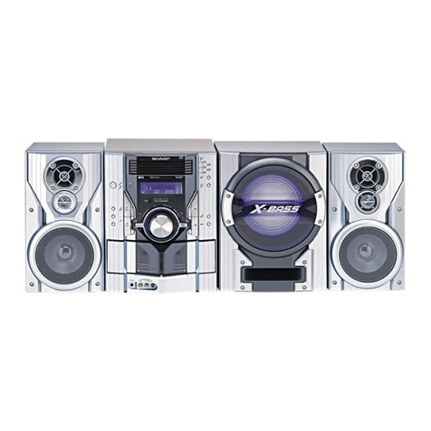
Sharp HT-DD5000W User manual

HT-DD5000W
– 1 –
Page
SPECIFICATIONS .................................................................................................................................................................. 2
VOLTAGE SELECTION......................................................................................................................................................... 2
NAMES OF PARTS ............................................................................................................................................................... 3
OPERATION MANUAL .......................................................................................................................................................... 4
DISASSEMBLY...................................................................................................................................................................... 6
ADJUSTMENT ...................................................................................................................................................................... 8
BLOCK DIAGRAM ................................................................................................................................................................ 11
SCHEMATIC DIAGRAM/WIRING SIDE OF P.W.BOARD................................................................................................... 16
NOTES ON SCHEMATIC DIAGRAM .................................................................................................................................. 38
TYPES OF TRANSISTOR AND LED.................................................................................................................................... 38
FUNCTION TABLE OF IC.................................................................................................................................................... 39
FL SEGMENT ...................................................................................................................................................................... 48
PARTS GUIDE/EXPLODED VIEW
CONTENTS
HT-DD5000W
No. SX886HTDD500W
• In the interests of user-safety the set should be restored to its original
condition and only parts identical to those specified should be used.
SERVICE MANUAL
SHARP CORPORATION
This document has been published to be used
for after sales service only.
The contents are subject to change without notice.
Manufactured under license from Dolby Laboratories.
"Dolby", "Pro Logic" and the double-D symbol are trade-
marks of Dolby Laboratories. Confidential Unpublished
Works. 1992-1997 Dolby Laboratories, Inc. All rights re-
served.
HT-DD5000WconsistingofHT-DD5000W,CP-F5000W,
CP-SW5000W,CP-C5000W and CP-SR5000W

HT-DD5000W
– 2 –
SPECIFICATIONS
HT-DD5000W
General
Type: Home theater receiver
Power source: AC 110/127/220/230 - 240 V
50/60 Hz
Power consumption: 160 W
Dimenslons: Width; 430 mm (16-15/16")
Height; 150 mm (5-15/16")
Depth; 347 mm (13-11/16")
Weight: 9.8 kg (21.6 lbs.)
Output power: (Front)
RMS; 40 W/CH (0.9% T.H.D.)
(Center)
RMS; 40 W (0.9 % T.H.D.)
(Surround)
RMS; 40 W/CH (0.9 % T.H.D.)
(Sub woofer)
RMS; 40 W (0.9 % T.H.D.)
Output terminals: Front speakers; 8 ohms
Center speaker; 8 ohms
Surround speakers; 8 ohms
Sub woofer; 8 ohms
VCR-1, MD/TAPE, VCR1 VIDEO,
VIDEO MONITOR
Headphones; 16-50 ohms
(recommended; 32 ohms)
Input terminals: DVD (Digital); Coaxial
DVD (Digital); Optical
DVD, VCR-1, VCR-2,CD/AUX,
MD/TAPE; 500 mV/47 kohms
PHONO; 3.5 mV/47 kohms
Tuner section
Frequency range: FM; 88 - 108 MHz
AM; 531 - 1,602 kHz
Front speaker section
Type: 2-way, 16 cm (6-5/16") woofer,
and 5 cm (2") tweeter
Maximum Input power: 80 W
Rated Input power: 40 W
Impedance: 8 ohms
Dimensions: Width; 210 mm (8-5/16")
Height; 330 mm (13")
Depth; 218 mm (8-5/8")
Weight: 3.7 kg (8.2 lbs.)/each
Center speaker section
Type: 2-way, 13 cm (5-1/8") woofer
and 5 cm (2") tweeter
Maximum Input power: 80 W
Rated Input power: 40 W
Impedance: 8 ohms
Dimensions: Width; 400 mm (15-3/4")
Height; 165 mm (6-1/2")
Depth; 163 mm (6-7/16")
Weight: 2.9 kg (6.4 lbs.)
Surround speaker section
Type: 2-way, 13 cm (5-1/8") woofer
and 5 cm (2") tweeter
Maximum Input power: 80 W
Rated Input power: 40 W
Impedance: 8 ohms
Dimensions: Width; 210 mm (8-5/16")
Height; 165 mm (6-1/2")
Depth; 163 mm (6-7/16")
Weight: 1.6 kg (3.5 lbs.)/each
Sub woofer section
Type: 16 cm (6-5/16") super woofer
Maximum Input power: 80 W
Rated Input power: 40 W
Impedance: 8 ohms
Dimensions: Width; 210 mm (8-5/16")
Height; 330 mm (13")
Depth; 340 mm (13-3/8")
Weight: 5.2 kg (11.5 lbs.)
CP-F5000W
CP-C5000W
CP-SR5000W
CP-SW5000W
Specifications for this model are subject to change without
prior notice.
VOLTAGE SELECTION
The voltage selector is located on the AC voltage selector box. If adjustment is necessary, use a screwdriver in order to turn the
selector in either direction until the correct voltage figure is displayed in the window next to the adjustment screw.
QACCE0008AW00
QACCL0005AW00
QPLGA0250AFZZ
Figure 2 AC POWER SUPPLY CORD AND AC PLUG ADAPTOR

HT-DD5000W
– 3 –
NAMES OF PARTS
HT-DD5000W
Front Panel
1. On/Stand-by
2. Remote Control Sensor
3. Stand-by Indicator
4. Timer Indicator
5. Display Panel
6. Dolby Surround Button
7. Eqalizer Button
8. Extra Bass Button: X-BASS
9. Volume Conrol
10. DVD Button
11. VCR-1 Button
12. Headphones Socket
13. Speaker A Button
14. Speaker B Button
15. CD/AUX Button
16. MD/TAPE Button
17. VCR-2 Button
18. PHONO Button
19. Tuner (Band) Button
20. Tuning Down Button
21. Tuning Up Button
22. Memory Button
23. Timer/ Sleep Button
24. Jog Dial
25. Enter Button
26. VCR-2 Input Sockets
Rear Panel
27. CD/AUX Input Sockets
28. DVD Input Sockets
29. VCR-1 Input/Output Sockets
30. DVD Digital Input Sockets
31. Video Monitor Output Socket
32. AM Antenna Terminal
33. Antenna Ground Terminal
34. FM Antenna Terminal
35. MD/TAPE Input/Output Sockets
36 Phono Input Sockets
37. Front Speaker Terminals
38. Center/Surround Speaker/Sub Woofer Terminals
39. AC Power Cord
40. AC Voltage Selector
Remote Control
1. Remote Control Transmitter LED
2. TV Power Button
3. On/Stand-by Button
4. TV CH Up/Down Button:
5. VCR CH Up/Down Button:
6. DVD Track Up/Down Button:
7. VCR Power Button
8. DVD Power Button
9. TV/VIDEO Button
10. TV/VCR Button
11. VCR Play Button:
12. VCR Stop Button:
13. DVD Stop Button:
14. DVD Play Button:
15. DVD Button
16. VCR-1 Button
17. VCR-2 Button
18. PHONO Button
19. CD/AUX Button
20. MD/TAPE Button
21. Dolby Surround Button
22. Eqalizer Button
23. Tuner (Band) Button
24. Extra Bass Button: X-BASS
25. Preset Balance Button
26. Menu Button
27. Sub Woofer Level Button
28. Mute Button
29. Set Up Up/Down Button:
30. Item Button
31. Volume Up/Down Button:
32. Tuner Preset Button:
1
10
11
12
13 141516171819 2021 22 23
24
25
26
52 3 94 6 7 8
32
2827 29 30 31
33
34
35 36 37 38
39
40
1
27
8
3
4
5
6
9
1011
12
13 14
15
1617 18
19
20
21
22
23
24
25
26
27 2829
30
31 32

HT-DD5000W
– 4 –
CP-C5000W
CP-SR5000W CP-SW5000W
1. Tweeter
2. Woofer
3. Speaker Cord
1. Tweeter
2. Woofer
3. Speaker Cord
1. Woofer
2. Bass Reflex Duct
3. Speaker Cord
CP-F5000W
1. Tweeter
2. Woofer
3. Speaker Cord
3
1
2
3
1
2
3
1
2
3
1
2
OPERATION MANUAL
0.2 m - 6 m
(8" - 20')
15˚ 15˚
■
Remote control
●When inserting or removing the batteries, push them to-
wards the battery terminal.
●Installing the batteries incorrectly may cause the unit to
malfunction.
Notes concerning use:
●Replace the batteries if the operating distance is reduced
or if the operation becomes erratic.
●Periodically clean the transmitter LED on the remote con-
trol and the sensor on the main unit with a soft cloth.
●Exposing the sensor on the main unit to strong light may
interfere with operation. Change the lighting or the direc-
tion of the unit.
●Keep the remote control away from moisture, excessive
heat, shock, and vibrations.
PREPARATION FOR USE

HT-DD5000W
– 5 –
(Continued)
■
AM/FM Interval (span)
The International Telecommunication Union (ITU) has estab-
lished that member countries should maintain either a 10
kHz or a 9 kHz interval between broadcasting frequencies
of any AM station. The illustration shows the 9 kHz interval
zones (regions 1 and 3), and the 10 kHz interval zone (region
2).
This product is not equipped with a span selector. However,
it will be adjusted to 9 kHz AM interval (50 kHz FM interval)
when shipped from the factory.
Before using the unit, be sure to set it for the AM tuning
interval (span) used in your area.
To check the tuning span currently selected:
1
Set the ON/STAND-BY button on the main unit to ON.
2
Press the TUNER (BAND) button until "FM" or "AM" ap-
pears in the display.
3
Press the TUNER (BAND) button to select the AM band.
●If "AM 531 kHz" is displayed, it means that the radio has
been adjusted for a 9 kHz span. If "AM 530 kHz" is dis-
played, it means that the radio has been adjusted for a
10 kHz span.
To change from a 9 kHz AM (50 kHz FM) interval to a
10 kHz AM (100 kHz FM) interval:
1
Press the ON/STAND-BY button on the remote control
to enter the stand-by mode.
2
Hold down the TUNER (BAND) button and the ENTER
button for at least 4 seconds. Release the buttons when
"AM SP 10 kHz" and "FM SP 100 kHz" are displayed
alternately.
To return to a 9 kHz AM (50 kHz FM) interval:
1
Press the ON/STAND-BY button on the remote control
to enter the stand-by mode.
2
Hold down the TUNER (BAND) button and the ENTER
button for at least 4 seconds. Release the buttons when
"AM SP 9 kHz" and "FM SP 50 kHz" are displayed al-
ternately.
Caution:
●When the unit is left for a few hours after the span has
been switched and AC power lead disconnected, it will
be automatically returned to a 9 kHz span. If this hap-
pens, set the span again.
●When the span is switched, any stations that are
memorised will be cancelled.
ON/STAND-BY
TUNER (BAND) ENTER
ON/
STAND-BY
[9 kHz →10 kHz]
(4 seconds)
[10 kHz →9 kHz]
(4 seconds)

HT-DD5000W
– 6 –
1 Top Cabinet 1. Screw ................. (A1) x5 6-1
2
Rear Panel/Video Jack
1. Screw ............... (B1) x16 6-1,2
PWB/Digital nput Jack
2. Socket ............... (B2) x5 6-2
PWB/Voltage Selector
PWB
3
Front Panel
1. Screw .................(C1) x8 6-2
2. Socket ................(C2) x5
3. Flat Cable ...........(C3) x2
4 Dolby PWB 1. Screw .................(D1) x3 7-1
2. Flat Cable ...........(D2) x2
3. Screw .................(D3) x4 6-3
5 Main PWB/Tuner 1. Screw ............... (E1) x12 7-1
PWB/Audio PWB 2. Socket ................ (E2) x7
6 Power PWB 1. Screw ................. (F1) x5 7-1
2. Socket ................ (F2) x2
7 Jog Dial 1. Knob ...................(G1) x1 7-2
2. Nut ......................(G2) x1
8 Display PWB 1. Screw ............... (H1) x10 7-2
2. Socket ................(H2) x2
9 Switch PWB 1. Screw ................. (J1) x2 7-2
10
Headphones PWB
1. Screw ................ (K1) x3 7-2
11
VCR Input PWB
1. Screw ................ (L1) x3 7-2
Caution on Disassembly
Follow the below-mentioned notes when disassembling
the unit and reassembling it, to keep it safe and ensure
excellent performance:
1. Take cassette tape and compact disc out of the unit.
2. Be sure to remove the power supply plug from the wall
outlet before starting to disassemble the unit.
3.Takeoffnylonbands or wireholderswheretheyneedbe
removed when disassembling the unit. After servicing
the unit, be sure to rearrange the leads where they were
before disassembling.
4. Take suff cient care on static electricity of integrated
circuits and other circuits when servicing.
DISASSEMBLY
Figure 6-2
Figure 6-1
HT-DD5000W
CP-F5000W
HT-DD5000W
STEP REMOVAL PROCEDURE FIGURE
1 Woofer/Tweeter 1. Net ........................(A1) x1 7-3
2. Screw .................... (A2) x6
REMOVAL PROCEDURESTEP FIGURE
CP-C5000W
STEP REMOVAL PROCEDURE FIGURE
1 Woofer/Tweeter 1. Net ........................(A1) x1 7-4
2. Screw .................... (A2) x6
CP-SR5000W
STEP REMOVAL PROCEDURE FIGURE
1 Woofer/Tweeter 1. Net ........................(A1) x1 7-5
2. Screw .................... (A2) x6
CP-SW5000W
STEP REMOVAL PROCEDURE FIGURE
1 Speaker 1. Net ........................(A1) x1 7-6
2. Screw .................... (A2) x4
Figure 6-3
(A1)x2
ø3x10mm
(B1)x15
ø3x10mm
(A1)x2
ø3x10mm
(A1)x1
ø3x10mm
Front Panel
Top Cabinet
Rear
Panel
Voltage
Selector PWB
(C1)x1
ø3x8mm
(C1)x1
ø3x8mm
(C1)x3
ø3x8mm
(B1)x1
ø3x10mm
(C1)x3
ø3x8mm
(C2)x1
Digital
Input Jack
PWB
Video
Jack
PWB
(B2)x2
Rear
Panel
Front
Panel
(C3)x2
(C2)x1
(C2)x1
(B2)x1
(C2)x2
(B2)x2
(D3)x4
ø3x6mm
Shield
Dolby PWB
HT-DD5000W
– 7 –
Figure 7-1
(D1)x1
ø3x8mm
(E1)x2
ø3x8mm
(D2)x1
(E2)x1
(F1)x4
ø3x8mm
Power
PWB
(E1)x6
ø3x8mm
(D1)x2
ø3x8mm
(E1)x2
ø3x8mm
(E1)x2
ø3x8mm(F1)x1
ø3x8mm
TRANS A
PWB
TRANS B
PWB
(E2)x2
(E2)x1
(E2)x1
(F2)x1
(F2)x1
(D2)x1
Audio
Jack
PWB
Tuner
PWB
(E2)x2
(L1)x3
ø3x10mm (H1)x10
ø3x10mm
(J1)x2
ø3x10mm (K1)x2
ø3x10mm
(K1)x1
ø3x10mm
(H2)x2
Front
Panel
Switch
PWB
VCR
Input Jack
PWB
Headphones
PWB
(G1)x1
(G2)x1
Display
PWB
Washer
Figure 7-4
Figure 7-3
CP-F5000W
CP-SW5000W
CP-C5000W
CP-SR5000W
Figure 7-6
Figure 7-5
Figure 7-2
(A2)x4
(A2)x2
Screw
driver
Drive should be pried
away from Speaker Box.
Direction of handle
Woofer Speaker
Box
(A1)x1
Tweeter
(A2)x4
(A2)x2
Screw
driver
Drive should be pried
away from Speaker Box.
Direction of handle
Woofer
Speaker
Box
(A1)x1
Tweeter
(A2)x2
(A2)x4
Screw
driver
Drive should be pried
away from Speaker Box.
Direction of handle
Speaker
Box
(A1)x1
Woofer Tweeter
(A2)x4
Screw
driver
Drive should be pried
away from Speaker Box.
Direction of handle
Woofer Speaker
Box
(A1)x1

HT-DD5000W
– 8 –
Figure 8 ADJUSTMENT POINTS
TUNER SECTION
fL: Low-range frequency
fH: High-renge frequency
Instrument
Connection
• FM RF
Signal generator: 1 kHz, 75 kHz dev., FM modulated
Test Stage Frequency Frequency
Display Setting/
Adjusting
Parts
Band — 87.5 kHz (fL): L202 *1
Coverage 3.4 ±0.1 V
RF 98 MHz 98.0 MHz L201 *2
(10 - 30 dB)
*1. Input: Antenna, Output: TP302
*2. Input: Anetnna, Output: Speaker Terminal
• FM Detection
Signal generator: 10.7 MHz, FM sweep
Test Stage Instrument
Connection
Frequency Frequency
Display Setting/
Adjusting
Parts
IF 10.7 MHz 98.0 MHz T202 Input: Pin 1
(Turn the of IC201
core of T202 Output:
fully counter- Pin 1of
clockwise) IC203
ADJUSTMENT
IF 450 kHz 1,602 kHz T204 *1
Band — 531 kHz (fL): T203 *2
(AM Band
Coverage
0.8V±0.1v
Tracking 990 kHz 990 kHz T201 *1
Test Stage Instrument
Connection
Frequency Frequency
Display Setting/
Adjusting
Parts
• AM IF/RF
Signal generator: 400 Hz, 30%, AM modulated
• Setting the Test Mode
Keeping the ENTER button and MEMORY button pressed,
turn on POWER (of Main Set). Then, the frequency is initially
set in the memory as shown in Table. Call it with the JOG to
use it for adjustment and check of tuner circuit.
Preset No.
1 87.50 MHz 6 531 kHz
2 108.00 MHz 7 1,602 kHz
3 98.00 MHz 8 990 kHz
4 90.00 MHz 9 603 kHz
5 106.00 MHz 10 1,404 kHz
11~40
FM Preset No. AM
*1. Input: Antenna, Output: TP301
*2. Input: Input is not connected, Output: TP302
*1. Adjust so that an output signal appears.
• FM Mute Level
Signal generator: 1 kHz, 40 kHz dev., FM modulated
Frequency Adjusting
Parts Instrument
Connection
Frequency
Display
98.0 MHz 98.0 MHz VR201 *1 Input: SOC201
(25 dBµV) Output: Speaker
Terminal
T201
AM TRACKING AM BAND
COVERAGE
T203
R216
TP302
L201
FM RF
IC201
T202 L202
FM IF VR201
FM MUTE
LEVEL T204
IC 203
TP301
R223
TUNER PWB
FM BAND
COVERAGE
SOC201
ANTENNA
TERMINAL
1
1
AM IF

HT-DD5000W
– 9 –
EXPLANATION OF AUTOMATIC SOUND VALUE CORRECTION CONTROL
1. Outline
The recent trend is toward rise of SOUND level in the world, for example rock, dancing music, etc. In case of continuous high
levelplaybackandVOL(Volume)arecontrolled(lowered)automaticallyafteralapse soastogettheeasy-to-listensoundlevel.
The ALC (Automatic Level Control) of the HT-DD5000 begins to operate immediately after the power is turned on.
2. Explanation of operation
The SOUND operation is explained below.
X
0v (The ALC will be functional
during this period.)
Distortion clip point
SP output
level
Power
ON
ALC operation
1
The ALC (Automatic Level Control) will begin operation immediately after the power switch is turned on.
2
If the sound exceeds level X , the ALC will instantaneously cut the volume back to level X , and it will also respond to
monophonic signals.
3
Since this control only effects the VOL level, it does not otherwise change the quality of the sound.

HT-DD5000W
– 10 –
DVD
DVD
When you connect this unit to a DVD player which is playing
a disc with the trademark, you can enjoy realistic,
powerful sound by playing back the recorded signal through
6 speakers with the sound coming from the front left, front
right, centre, surround left, surround right and sub woofer
speakers.
To listen to a disc using the Dolby Digital mode:
1Connect a DVD player.
2Press the DVD button.
●The current DVD input channel will be displayed. If the
DVD button is pressed whilst the current DVD channel is
displayed, the input channel (ANALOG, COAXIAL, OPTI-
CAL) can be changed.
3Start the DVD player.
Note:
●When the Dolby Digital surround mode is being used, the
equalizer will be set to FLAT.
Type of Dolby digital signal
There are different types of Dolby digital signals. When you select COAXIAL or OPTICAL for the DVD input channel, the
following items will be displayed for 2 seconds. They will also be displayed when the DVD player is operating and the DVD
button is pressed.
Display Channels available Display Channels available
Normal PCM playback Front (L, R) + surround
(L, R)
Centre only (monaural) Front (L, R) + centre
Front (L, R)
(When the surround mode
is set to Normal, Phantom
or Wide sound will also be
heard from the surround
speakers.)
Front (L, R) + centre +
surround (monaural)
Front (L, R) + surround
(monaural) Front (L, R) + centre +
surround (L, R)
DIGITAL
DIGITAL
DIGITAL
DIGITAL
DIGITAL
DIGITAL
DIGITAL
●If a low frequency sound effect (Low Frequency Effect) contains a Dolby digital signal, "LFE" will light in the display.
When this "LFE" is lit, low frequency signals will be output from the sub woofer.
DOLBY DIGITAL
When Dolby digital signals are input, the display will light up
or go out, as shown to the left.
The channel speaker and SW indicators are used to set the
sound for listening in the surround mode and will light up
according to the speaker signals that are present.
➀Lights up if the input contains a left channel signal.
➁Lights up if the input contains a centre channel signal.
➂Lights up if the input contains a right channel signal.
➃Lights up if the input contains an "LFE" signal.
➄Lights up when the amplifier setting will output sound to
sub woofer.
➅Lights up if the input contains a left surround signal.
➆Lights up if the input contains surround signals.
➇Lights up if the input contains a right surround signal.
➀➁➂
➃➄
➅➆ ➇

HT-DD5000W
– 11 –
Figure 11 BLOCK DIAGRAM (1/5)
TO DISPLAY SECTION
7
1
TOS
DVD
DIGITAL
IN
IN
DVD
DIGITAL
IN
1
11
~
13
16 15
IN IN
61
7 9
12 13 5
DEM0
DEM1
XT1
BICK
6
PD
16 20 22 2 14 15 24
8
1817
1
3
10
11
21
A-GND
CENTER
SUB
WOOFER
IN
CENTER
SUB
WOOFER
14
13
D-OUT
DEM0
DEM1
16 17 15
SCK
7 912 13 5
DEM0
DEM1
XT1
BICK
6
PD
16 20 22 2 14 15 24
8
FL/FR
IN
1817
FL FR
1
3
10
11
21
A-GND
83
79
91
D-IN
CLK_L/R OUT
92
CLK_OUT
97
95
66
CLK_L/R
CLK
SCK
SCK_IN
5
55
59
67
70
81
84
93
6
12
17
30
35
45
48
90
78
94
86
85
62
60
36
4
2
8
19
29
37
44
53
65
68
71
OUT
D-OUT
D-IN
SL/SR OUT
SL/SR IN
4
7
IN
2
1
6
7
6
3 4 5 6
23
24
PWDA
PWAD
AINR+
2 8
18 19 20 22 25
1
7
9
10
21
AINR–
OUT AINL–
IN
AINL+
OUT
ININ
OUT
A-GND
8 4
2
1
8
A-GND
A-GND
27
RS OUT
LS OUT
26
SUB
WOOFER
OUT
FL/FR
OUT
LS/RS
OUT
9
14
SS
SO
SCK
SI
DEMO1
DEMO0
AC3 RESET
AD RESET
4
8
SUB
WOOFER
IN
4
5
6
1213
11
10
A-GND
7
14
8
1
9
2
5
7
SUB
WOOFER
OUT
SUB
WOOFER
ON/OFF SWITCHING
FL/FR
GND
VDD
48
3 5
1 7
MIX
IN
L R
OUT
SUB
WOOFER
J802
GP1F38R
IC805
TC7WU04F
INVERTER
IC806
TC74HC15
INVERTER
7 6
2
4
3
8
6 5 3 4
16
D_SEL
IC802
NJM4580M
OPE AMP. IC801
NJM4580M
OPE AMP.
IC803
AK4520A
20BIT 2CH
A/D,D/A
CONVERTER
IC808
ZR38600
DOLBY AC-3/5.1CH
MPEG2 AUDIO
DECORDER
IC809
AK4321VF
D/A
CONVERTER
IC810
AK4321VF
D/A
CONVERTER
IC811
NJM4580M
OPE AMP.
IC812
TC4066BF
ANALOG SWITCH
IC813
NJM4580M
MIX AMP.
Q801
Q802 Q803
AC3-GND AC3-GND
AC3_3V
AC3_3V
A_5V
A_5V A_5V
SW-ON
RT_CH LT_CH
CLK
CLK_L/R
12 11
AC3D_GND
8
D_SEL
AC3D_GND
54
CENTER SUB
WOOFER
OUT
99
80
89
87
82
34
3
SS
SO
FL/FR OUT
88
AC3D_GND
–7V
+7V
+7V
–7V
+7V
A_5VA_5V
AC3D_GND
AINL–
AINL+
AINR–
AC3_3V
2
CENTER
OUT
–7V
LRCK
LRCK
AC3_3V
SI
SCK
RESET

HT-DD5000W
– 12 –
Figure 12 BLOCK DIAGRAM (2/5)
220V
230-240V
127V
110V
T.F
Q611
D
6
RLY601
POW-1
D623-D626
D622
D621
Q405 F608
T800mA L 250V
T602
POWER
TRANSFORMER
Q406
Q620
VOLTAGE
REGURATOR
Q622
VOLTAGE
REGURATOR
VOLTAGE
REGURATOR
VOLTAGE
REGURATOR SWITCHING
+7V
A+12V(ANALOG)
A-12V(ANALOG)
VH(+)
VH(–)
–7V
µ-COM5V Q601
VOLTAGE
REGULATOR
SWITCHING
POW-2
VOLTAGE
REGULATOR
Q602
Q603
SWITCHING
POWER SW
µ-COM
FL VF1,VF2,–VPP VP VF2
(AC)
VF1
(AC)
Q623
Q625
SWITCHING
VOLTAGE
REGURATOR
VOLTAGE
REGURATOR
AC3_3V
A_5V
VL(–)
VL(+)
D627-D630
P_GND
M_GND
A_GND
D_GND
AC3_GND
VOLTAGE
REGULATOR
µ-COM_GND
AC3D_GND
V_GND
R-CH IN
L-CH IN
S_WOOFER IN
IC701
STK41
0
POWE
2
38
1
18
22
24
VH(+)
VH(–)
IC751
STK41
0
POWE
2
38
1
18
22
24
VH(+)
VH(–)
REAR_L IN
REAR_R IN
CENTER IN
µ-COM
PROTECT
VOLUME
SECTION
F611
T1A L 250V
F601
T2.5A L 250V
F606
T4A L 250V
F607
T4A L 250V
Q621
Q624

HT-DD5000W
– 13 –
VOLTAGE
SELECTOR
D601-D604
POWER
TRANSFORMER
T601
R
C
HING
+
+
–GND
– GND
+
+
– GND
– GND
SO681
CENTER/SURROUND
SPEAKER
/SUB WOOFER
TERMINAL
SUPER
WOOFER
CENTER
SURROUND L-CH
SURROUND R-CH
SWITCHING
REAR R-CH OUT
REAR L-CH OUT
RLY682
RLY681
RLY654
+ FRONT-A
L-CH
FRONT-A L-CH OUT
RLY651
+ FRONT-A
R-CH
– GND
– GND
+
+
FRONT-B
L-CH
RLY652
Q651
Q654
– GND
Q656
Q682
Q681
Q653
– GND
CENTER OUT
SWITCHING
SWITCHING
FRONT-A R-CH OUT
Q652
Q655
RLY653
SUPER WOOFER OUT
SWITCHING
SW RLY
C-RLY
R-RLY
B-SP
A-SP
µ-COM
IC701
STK41009
POWER AMP.
87
14
12 14
15
26
VH(+) VL(+)
VH(–) VL(–)
POSISTOR
µ-COM
IC751
STK41009
POWER AMP.
87
1
4
12 26
15
14
VH(+) VL(+)
VH(–) VL(–)
POSISTOR
µ-COM
Q703
Q704
Q705
Q706
Q707
Q756
Q757
Q753
Q754
Q755
FRONT-B
R-CH
FRONT-B L-CH OUT
SWITCHING
SWITCHING
SWITCHING
SP-A
SP-B
SP-A/B
SELECT
SWITCH
F603
T100mA L 250V
AC POWER SUPPLY CORD
AC 110/127/220/230-240V
50/60Hz
F602
T5A L 250V
SO651
FRONT
SPEAKER
TERMINAL
Figure 13 BLOCK DIAGRAM (3/5)

HT-DD5000W
– 14 –
Figure 14 BLOCK DIAGRAM (4/5)
FM IF
1
20 22 15 16 11 12 17
21
6
3 4 5
7
2 3
21222324
7 6
1
2
3 4
9
8
5 6 7
1
4 5 8 9 17
1413121110
18 19 16
9
15
10
3
1
8
5
7
4
2 6
14
10
1113
12
4
8
3
5 1
7
4
8 3
5
1
7
4
8 3
5
1
7
1
2
3
4
567
2726252423
28
15 16 17
12 21
22
19
10
11
18
1314
8
3
5
3
5
3
5
3
5
4
8 3
5
1
7
AM RF
AM IF
FMOSC
IC202
LC72131
PLL (TUNER)
X352
4.5MHz
FM IF
VOLTAGE
REGURATER
SD
AM LOOP ANT
AM ANT
FM RF
L201 FM IF
T202
FM OSC
L202
FM IF
AMP
FM +B
IC201
FM FRONT END
TA7358AP
Q201
CF201Q281
IF AMP
T204
IC203
LA1833
FM/AM IF MPX.
CF203
CF202
Q202
MUTING TUNER MUTE
VR201
FM MUTE LEVEL
A+12V
A+12V
STEREO
L
R
MD/TAPE
INPUT
MD/TAPE
OUTPUT
PHONO
INPUT
DVD
INPUT
CD/AUX
INPUT
VCR1
OUTPUT
VCR1
INPUT
J405
J406
J404
L
R
VCR2
AUDIO
INPUT
VCR2
VIDEO
INPUT
VCR1
VIDEO
INPUT
VCR1
VIDEO
OUTPUT
DVD
VIDEO
INPUT
MONITOR
OUTPUT
J401
Q505
Q506
IC402
TC9273F
FUNCTION SWITCH
Q507
Q508
BUF
F
I
C
NJ
M
BUF
F
I
C
NJ
M
HEA
D
A
I
C
NJ
M
OPE AMP.
IC405
NJM4580M
MOTOR DRIVE
IC404
NJM4558M
SWITCHING
SWITCHING
IC411
NJM4565M
IC412
NJM4565M
BUFFER AMP.
+B12V
+B12V
SOC201
ANTENNA
TERMINAL
FM ANT
AM OSC
T203
IC403
NJM2279D
VIDEO SWITCH
BUFFER AMP.
BUFF
E
IC
4
NJM
4
DATA
STB
S7
VDD
CK
GND
VSS
S1
S2
S3
S4
S5
S6
S9
S10 FM IN
AM IN
STEREO
OUT
AM
OUT
IF
OUT
MPX
IN
L
MPX
VCO
CUT
DI
CL
CE
DO
XT21
+5V
VT
FM IF
VT
FM
FM
OUT
AM
OUT
REQ GND VCC
FM
DET
AM IF
IN
IN
IN
IN
IN
IN
IN
OUT
IN
OUT
Vout1
Vout2
MUT1
MUT2
V_SW1
OUT
FM IF IN
TO POWER SECTION
D
E
D
E
T201
OSC
AFC
AM RF IN
IN
SD
PHASE
AM/FM
IF IN
V_SW2
A+12V
A–12V
AC3-RES
AC3-SS
TO DOLBY SECTION
AD RESET
+7V
–7V
–7V
+7V
–7V
+7V
+7V
–7V
+7V
–7V 1
2
3
4
5
6
7
8
9
10
11
12
13
14
15
16
17
18
19
20
21
30
31
32
33
34
35
36
37
38
39
40
41
42
29
28
27
26
25
24
23
22
IC401
M62446FP
6CH ELECTRONIC VOLUME
OUT4(NC)
OUT3(NC)
SRIN
SLIN
C_IN
GNDR
GNDS
LBYPASS3(NC)
LBYPASS2(NC) RBYPASS3(NC)
RBYPASS2(NC)
CL1(NC)
CL2(NC)
RTRE(NC)
AVSS
C_OUT
R_OUT
SW_OUT
RL_OUT
RR_OUT
A_GND
D_GND
DVDD
CLK
DATA
+B5V
LATCH
+7V
LT/RT_CH
FL
FR
SUB-W
DOLBY SECTION
LS/RS
CENTER
Q501
Q504Q503
FRONT LEVEL
ADJUSTING
OUT
OSC
Q203
+B5V
R
AC3-SO
DEM1
DEM0
SW-ON
AC3-SCK
D-SEL
AC3-SI
L
R
L
R
L
R
L
R
L
R
L
R
OSC
S11
LBYPASS1(NC) RBYPASS1(NC)
CR2(NC)
CR1(NC)
L_OUT
SWIN
AVDD
OUT1(NC)
OUT2(NC)
GNDC
LTRE(NC)
BYPASSL(NC)
BYPASSR(NC)
L_IN
GND
R_IN
MUTE
MUTE
BF201
BANDPASS
FILTER
1 3

HT-DD5000W
– 15 –
Figure 15 BLOCK DIAGRAM (5/5)
M
3
1 2 3 4 5 6 7 8 10 11 12 13 14 15 16
17 18 19 20 23 24 25
21 22 26
27
28
29
30
31
32
33
34
35
36
37
38
39
40
41
42
43
44
45
46
47
48
49
50
5152
53
54555657
58
5960616263646566676869
70
71
72
737475
9
100
XL2
8MHz
4
8
3
5 1
7
4
8
3
5 1
7
4
8
3
5 1
7
4
8
3
5 1
7
76
77
78
79
80
81
82
83
84
85
86
87
88
89
90
91
92
93
94
95
96
97
98
99
XL1
32.768 kHz
REMOCON RX1
REMOTE
SENSOR
Q7
Q8
ZD1
IC1
IX0004SJ
SYSTEM
MICROCOMPUTER
Q411
Q412
Q413
Q414
J581
HEADPHONES
VF1
(AC) VF2
(AC)
Q409
Q410
C_MUT
SW_MUTE
BACK UP
BUFFER AMP.
IC407
NJM4565M
BUFFER AMP.
R_MUT
IC406
NJM4565M
F_MUT
HEADPHONE
AMP.
IC581
NJM4565D
HP_MUTE
SWITCHING
SWITCHING
SWITCHING
SWITCHING
SWITCHING
Q6 Q13
Q671
Q672
RESET
µ–COM25V
BUFFER AMP.
IC408
NJM4565M
PROTECT
FAN
TUN–DI
TUN–DO
TUN–CK
TUN–CE
TUN–MUTE
TUN–SD
TUN–ST
VDD
OSC2
OSC1
VSS
XI
XO
MMOD
VREF–
KEY1
KEY2
KEY3
AREA
SP–LEVEL
MODEL
POSISTER LED1
P12
P11
P10
P9
P8
P7
P6
P5
P4
P3
P2
P1
10G
9G
8G
7G
6G
5G
4G
3G
2G
1G
P14
P15
P16
NC
NC
NC
NC
DAPD
ADPD
AC3–RES
AC3–SS
AC3–SI
D–SEL
AC3–SCK
SW–ON
PRO–ENA
PRO–DI
PRO–CK
V–SW1
V–SW2
V–MUTE
P13
FL1
DISPLAY
SPSWB
SPSWA
SW–RLAY
C–RLAY
R–RLAY
HP MUTE
POW–SW
FA–RLAY
SW–MUTE
C–MUTE
R–MUTE
F–MUTE
JOG DOWN
JOG UP
REMOCON
AC3–SO
SYS–STOP
POWER
V–DATA
V–CK
V–LACH
FS–CK
FS–DATA
FS–STB
RESET
VREF+
IN OUT
IN
IN OUT
IN
OUT
KEY MATRIX
SW4–SW8
SW9–SW15
SW16–SW19
STAND–BY LED
LED1
TIMER LED
LED2
µ–COM25V
S_WOOFER
FRONT L,R
CENTER
TO POWER AMP. SECTION
SPEAKER A,B SW
TO POWER AMP SECTION
TO POWER SECTION
REAR2 L,R
µ–COM25V
DEM0
DEM1
2
JOG
SW23
POWER
SW1
TO POWER AMP. SECTION
AC3-RES
AC3-SS
AD RESET
A+12V
A–12V
A+12V
A–12V
A+12V
A–12V
A+12V
A–12V
Q11
Q12
SWITCHING
Q1~Q4
SWITCHING
Q9
SWITCHING
Q407
Q408
VPP
ALC
Q10
1
AC3-SO
DEM1
DEM0
SW-ON
AC3-SCK
D-SEL
AC3-SI
OUT
M671
FAN
MOTOR

HT-DD5000W
– 16 –
A
B
C
D
E
F
G
H
123456
Figure 16 SCHEMATIC DIAGRAM (1/12)
NOTES ON SCHEMATIC DIAGRAM can be found on page 38.
CNP201
CNS1BCNP403CNS801B
FC801
6 5 4 3 2 1 21
FC1
12
11
10 9 8 7 6 5
20
19
18
17
16
15
14
13
12
11
10 9 8 7 6 5 4 3 2 1
18 17 16 15 14 13 12 11 10 987654321
C629
47/25
R620
1.5K
C637
3300/25
D626
1N4004S
D625
1N4004S
D622
BR102J02
C638
47/25
D628
1N4004S
ZD622
MTZJ130C
Q623
KTC3199 GR
Q624
2SD2012 Y
D630
1N4004S
D629
1N4004S
C
6
0
ZD623
MTZJ6.2B
C626
C633
4700/25
D624
1N4004S
D621
BR102J02
D62
3
1N400
4
D62
7
1N400
4
D632
1N4148
C476B
10/50
Q406
2SB562 C
ZD402
MTZJ7.5C
C478
1/50
R496B
270
C628
0.022
C627
220/25
Q620
2SB1375 Y
ZD621
MTZJ13A
C475B
10/50
C641
1000/6.3
Q405
2SD468 C
ZD401
MTZJ7.5C
C477
1/50
R495B
270
C640
47/25
Q625
2SD468 C
R628
22
ZD624
MTZJ3.9B
R627
82
C639
220/16
D631
1N4148
Q622
2SD2012 Y
R622
1K
R624
47 Q621
KTC3199 GR
C634
47/25
C615
47/50
CNP4
ZD612
MTZJ6.8C
R614
100
R616
220
ZD611
MTZJ330C
Q611
KTA1266 GR
C616
100/35
R615
12K
R613
2.2K
7
6
5
4
3
2
1
8
Q603
KTC3199 GR
R606
1K
Q602
2SD468 C
R605
47
ZD602
MTZJ5.6B
C606
47/16
C619
0.047
C618
0.047
R608
47K
R607
10K
C617
100/35
R617
220
7
6
5
4
3
2
1
TO AC3
TO DOLBY PWB
P24 5-H
CNS801A
18 1
TO VIDEO
JACK PWB
P20 5-A
CNS403
CNS1A
TO DISPLAY PWB
P22 1-E
21 1CNS201
TO TUNER
P
P27 12-G
DEM1
AC3_SI
AC3_SS
AC3
_
RES
ADPD
DAPD
V_SW2
V_SW1
V_MUTE
D_SEL
SW_ON
AC3
_
SCK
DEM0
A+12V
D_GND
A+12V
–7V
A+12V
VL(–)
M_GND
+7V
A–12V
VL(+)
P_GND
VH(–)
VH(+)
VOLTAGE
REGURATOR
VOLTAGE REGURATOR
VOLTAGE
REGURATOR
VOLTAGE
REGURATOR
SWITCH
VOLTAGE
REGURATOR VOLTAGE
REGURATOR
TO DISPLAY PWB
P23 7-H
CNS4
POW_SW
VF1
µ–COM_5V
D_GND
VF2
–VPP
POW_1
POW_2
VOLTAGE
REGULATOR
SWITCHING
SWITCH
FM SIGNAL
AC3D_GND
AC3_SO
–7V
+7V
A_5V
AC3_3V
AC3_GND
TUN_MUTE
TUN_CK
TUN_DO
TUN_CE
TUN_DI
TUN_SD
TUN_ST
AC3D_GND
A_GND
D_GND
V_GND
AC3_GND
AC3_3V
A_5V
MAIN PWB-A(1/2)
POWER PWB-D2
+B
+B
–B
+B –B
–B +B
+B
+B
–B
–B
+B
+B
–B
+B
+B
+B
+B
0V
0V
0.5V
7.3V 4.7V
–32V –35.9V
VOLTAGE
5.3V
–32.6V
–7.2V
–7.8V
–12V
–12V –21.6V
–12.8V
12.2V 16.9V
13V 16.9V
13.6V
7V 12.2V
7.6V
3.4V
4.0V
4.9V 4.9V
11.6V
5.5V
11.6V
R625
330
6.18V
TO POWER
AMP.SECTION
P18 1-E
–
–
+
+
~
~
~
~

HT-DD5000W
– 17 –
78 9 10 11 12
Figure 17 SCHEMATIC DIAGRAM (2/12)
VOLTAGE
110V
127V
220V
230-240V
No.
3-4, 7-8
8-1, 4-5
2-3, 6-7
1-2, 5-6
SWITCH POSITION
F601
T2.5A L 250V
CNS2B
201 CNP502 CNP501
16151413121110
987654321
1817 2019
1 10 9 8 7 6 5 4 3 2 1 11
10
9
8
7
6
5
4321 8
7
6
5
4321
FC2
D626
1N4004S
2
5
0
4S
C623
0.1
6
22
0
2J02
D
628
N
4004S C635
0.047
D630
1N4004S
D
629
4
004S
C624
0.1
C626
0.047
6
24
0
04S C631
0.047
F606
T4A L 250V
F607
T4A L 250V
F608
T800mA
L 250V
1
2
J02
C621
0.1
C622
0.1
C625
0.047
C632
0.047
D623
1N4004S
C636
0.047
D627
1N4004S
T602
POWER TRANSFORMER
CNP601
F611
T1A L 250V
CNP602
CNP603
C615
47/50
R611 1
D603
1N4004S
C611
100/50
R604
47
Q601
2SD468 C
C604
47/16
ZD601
MTZJ6.8A C603
2200/16
R614
100
C602
0.047
ZD611
MTZJ330C
Q611
KTA1266 GR
100/35
D601
1N4004S
R613
2.2K
C605
0.022
C607
0.022
D604
1N4004S
C601
0.047
D611
1N4004S
D612
1N4004S
C612
100/50
D613
1N4004S
C613
47/63
D614
1N4004S
C614
220/63
D602
1N4004S
R612 1
R610
THERMISTOR
1
2
3
4
6
5
7
13
12
11
10
9
8
1
2
3
4
6
5
7
13
12
11
10
9
8
1
2
3
4
6
5
7
13
12
11
10
9
8
CNS602
BI602
CNS603
5
4321
5
4321
5
4321
BI603
F603
T100mA L 250V
C608
0.0047
2
1
3
5
4
2
1
3
5
4
2
1
3
5
4
CNS601
BI601
1 12234
1 12234
CNS6A4 CNS6B4
BI6B4BI6A4
SW601
VOLTAGE
SELECTOR
CNP6B4
CNP6A4
1 12234
RLY601
D607
1N4004
T601
SUB POWER TRANSFORMER
C610
0.0047
R605
47
C606
47/16
C619
0.047
C618
0.047
F602
T5A L 250V
8
9
10
11
12
13
14
15
R603
820
C609
0.047
CNS201
TO TUNER PWB
P27 12-G CNS502
TO AUDIO
JACK PWB
P21 10-A CNS501
TO AUDIO
JACK PWB
P21 9-A
TO DISPLAY PWB
P23 12-D
CNS2A
20
1
A_GND
A_GND
A+12V
A+12V
TUN_L
D_GND
TUN_L
TUN_R
TUN_R
FS_STB
FS_DATA
FS_CK
+7V
–7V
A–12V
D_GND
AC3_SO
SW_MUTE
F_MUTE
C_MUTE
R_MUTE
SW_RLY
C_RLY
FA_RLY
R_RLY
A_5V
R_MUTE
C_MUTE
V_CK
V_LATCH
V_DATA
F_MUTE
SW_MUTE
PROTECT
FAN_SW
V_LATCH
V_DATA
V_CK
FS_CK
FS_DATA
FS_STB
SP_LEVEL
POSISTOR
T.F.
1
2
3
4
5
6 7 8
(242)
(242)
SWITCHING
VOLTAGE REGULATOR
R
AC POWER
SUPPLY CORD
AC110/127/220/230–240V
50/60Hz(220)
TRANS A/B PWB-D3,D4
VOLTAGE SELECTOR
PWB-D9
4.7V
–32V –35.9V
VOLTAGE REGULATOR
5
.
3V
–32.6V
5.6V
6.3V
7.2V +B
+B +B
+B
+B
–B
–B
TO POWER
AMP.SECTION
P18 1-E
P18 1-B
–
–
+
+
~
~
~
~
220/230-240V
127V
110V
0V

HT-DD5000W
– 18 –
A
B
C
D
E
F
G
H
123456
Figure 18 SCHEMATIC DIAGRAM (3/12)
NOTES ON SCHEMATIC DIAGRAM can be found on page 38.
C764
15P
D741
1N4004
D677
D
6
1
N
D674
D782
1N5402M
D781
1N5402M
D732
1N5402M
D740
1N4004
D731
1N5402M
D756
1N4148
D755
1N4148 D706
1N4148
D705
1N4148
ZD752
MTZJ7.5C
ZD751
MTZJ7.5C
ZD702
MTZJ7.5C
ZD701
MTZJ7.5C
CNP701
C703
2.2/50
C778
220/10
Q756
KTC3199 GR
R791
56K
Q757
KTC3199 GR
Q755
KTC3199 GR
D753
1N4148
D754
1N4148
Q706
KTC3199 GR
C728
220/10
R741
56K
Q707
D704
1N4148
Q705
KTC3199 G
D703
1N4148
C782 100/35
R768
56K
R734
0.2 (1W)
L753
0.3µH
R753
4.7(1/2W)
R752
4.7(1/2W)
R751
4.7(1/2W)
L752
0.3µH
L751
0.3µH
C772
0.22(ML)
R772
4.7(1/2W)
C770
0.22
(ML)
R771
4.7(1/2W)
C771
0.22(ML)
C769
0.22
(ML)
R767
56K
R766
1K C763
15P
R703
4.7(1/2W)
R702
4.7
(1/2W)
R701
4.7(1/2W)
R717 56K
R718
56K
C713
15P
R716
1K
L701
0.3µH
R721
4.7(1/2W)
C719
0.22
(ML)
C721
0.22(ML)
C755
2.2/50
C754
2.2/50
C753
2.2/50
C705
2.2/50
C704
2.2/50
L702
0.3µH
R722
4.7
(1/2W)
C720
0.22
(ML) C722
0.22(ML)
R715
1K
R
2
ZD671
MTZJ5.1A
R675
10K
R754 33K
R755
390
R705
390
C751
4700/ 50 C752
4700/50
C701
4700/35
C702
4700/35
R723
4.7
(1/2W)
C724
0.22(ML)
C723
0.22
(ML)
R740
56K
R739
56K
R738
56K
R710
56K
C716
0.001(ML)
R708
56K
C718
0.001
(ML)
C736
100/50
C735
100/50
C734
100/50
C732 100/35
C731
100/35
C733
100/50
R713
1.2K
C710
100/50
C712
100/50 R712
1K
C711
100/50 R711
1K
C717
0.001(ML)
R707
56K
C714
15P
L703
0.3µH
R720
56K
C715
15P R719
1K
R744
3.9K
R745
3.9K
D701
1N4148
R736
4.7K
R737
4.7K
C727
0.022
R735
0.2(1W)
R729
4.7K
Q703
KTC3199 GR
R730
4.7K
D702
1N4148
Q704
KTC3199 GR
R732
4.7K
C726
0.022
(ML)
R728
0.2
R726
0.2(1W)
R725
0.2(1W)
R727
0.2(1W)
C725
0.022(ML)
R731
4.7K
R709
390
R706
390
R704
33K
R743
100(1/2W)
R742 100(1/2W) C709
47P
C708
47P
C707
47P
R762
1K
Q754
KTC3199 GR
C766
0.001(ML)
C759
47P
R765
1K
R785 0.2(1W)
R756
390
C758
47P
C785 100/50
R778
0.2(1W)
R781
4.7K
R794
3.9K(1/4W)
R795
3.9K(1/4W)
R784
0.2(1W)
R769
1K
C773
0.22(ML)
R786
4.7K
R757
56K
C786 100/50
R792 100(1/2W) Fusible
R763
1K
R782
4.7K
R790
56K
C768
0.001
(ML)
R758
56K
C765
15P
C760
100/50
R777 0.2(1W)
C781 100/35
C767
0.001(ML)
Q753
KTC3199 GR
C784 100/50
R759
390
R780
4.7K
R793
100(1/2W) Fusible
R779
4.7K
C776
0.022
(ML)
R761
1K
R760
56K
C775
0.022(ML) C757
47P
D752
1N4148
C774
0.22
(ML)
R773
4.7
(1/2W)
R788
56K
C783 100/50
D751
1N4148
R776 0.2(1W)
C762
100/50
R770
56K
C777
0.022
(ML)
R775 0.2(1W)
R787
4.7K
C761
100/50
R789
56K
1 2 3 4 5 6 7 8 9 10 11 12 13 14 15 16 17 18 19
20 21 22 23 24 25 26
IC701
STK41009
POWER AMP.
IC751
STK41009
POWER AMP.
1 2 3 4 5 6 7 8 9 10 1112 13 14 15 16 17 18 19
20 21 22 23 24 25 26
1
2
3
4
5
1
2
3
4
5
9
1
2
3
4
5 BI702
CNS702
5
14
4
3
10
13
1
2
6
7
15
8
12
11
A_GND
REAR_L
REAR_R
CENTER
P_GND
+
–
–
+
–
+
––
+
+
+
–
–VH
PROTECT
SP_LEVEL
M_GND
FAN_SW
R_RLY
C_RLY
A+1_V
SW_RLY
FA_RLY
–VL
+VH
+VL
23V
24V
19V
–18V
–24V
–39V
–23V
–23V
–23V
0V
0V
38V
0V
0V
0V
–37V
37V
0V
0V
–36V
0V
0V
–23V
0V
0V
0V
0V
5V
0V
5V
0V
5V
0V
0V
0V 5V
0V
0V
0V
A_GND
FRONT_R
SW
POSISTOR
FRONT_L
CNS701
P17 12 - C
TO MAIN SECTION
P16 1 - D,P17 12 - C
TO MAIN SECTION
P21 12 - E
TO AUDIO JACK PWB
FM SIGNAL
0V
5V
CNP702
P21 12 - D
TO AUDIO JACK PWB
(1W)
MAIN PWB-A (2/2)

HT-DD5000W
– 19 –
78 9 10 11 12
Figure 19 SCHEMATIC DIAGRAM (4/12)
CNP653
D679
1N4148
D678
1N4148
D677
1N4148
D676
1N4148
D675
1N4148
D674
1N4148
SO681
CENTER/SURROUND
SPEAKER/SUB
WOOFER TERMINAL
C677
0.001
(ML)
C681
0.001
(ML)
C689
0.001
(ML)
C688
0.001
(ML)
C666
0.001
(ML)
C665
0.001
(ML)
C657
0.001
(ML)
C658
0.001
(ML)
C673
47/25
SO651
FRONT SPEAKER
TERMINAL
0
R791
56K
Q757
KTC3199 GR
GR
D753
1N4148
D
754
4
148
56K
Q707
KTC3199 GR
D
704
4
148
Q705
T
C3199 GR
D
703
4
148
R686
10K
R657
1K
RY654
RY682
RY681
R674
22K
7
1
A
R675
10K
C671
10/50
D671
1N4148 D672
1N4148
C672
10/50
R676
22K
R677
10K
Q671
KTC3199 GR
R678
3.9K
ZD672
MTZJ4.7C
Q672
KTA1270
Q681
KTC3199 GR
R685
47K
R684
10K
R653
3.3K
R652
47K
D651
1N4148
R651
3.3K
D653
1N4148
Q653
KTC3199 GR
R656
47K
R655
3.3K
Q651
KTC3199 GR
R654
47K
Q652
KTC3199 GR
D652
1N4148
Q654
KRC102 M
D654
1N4148 D655
1N4148
Q655
KRC102 M
R679
47
R661
3.9K
Q657
KTA1270
Q682
KTC3199 GR
D681
1N4148
R659
47K
R662
10K
D682
1N4148
R687
47K
Q656
KTC3199 GR
Q658
KTC3199 GR
R663
47K
R658
10K
D656
1N4148
RY653
RY652
RY651
2
3
1
1
2
3
4
5
6
7
8
1
2
3
4
5
6
7
8
1
2
FW654
1
2
M
M671
CNS611
1
2
CNP611
CNP612
1 1
2 2
BI612
CNS612
R673
5.6K
REAR–R–OUT
REAR–L–OUT
CENT–OUT
S.W–OUT
B–FR–R–OUT
B–FR–L–OUT
SUPER–WOOFER–GND
SUPER–WOOFER
SP–CENTER
SP–CENTER–GND
5V 0V
0V 5V
0V
0
V
0
V
0V
12.5V
0V
0V
0V
0V
0V
7.67V
0.8V
0V
13.9V0V
0V
0.7V
12.3V
12.48V
0V
0V
12V
11V
0V
0V
0V
11.9V
0.7V
0.7V
0V
0V
11.7V
0.1V
0V
0.8V
0.7V
0V
0V
Q651~Q655:SWITCHING
1
23
1
2
3
SP–A–L–CH–GND
SP–A–R–CH–GND
SP–A–L–CH
A-SP
12V
1
3
CNS653
FAN
MOTOR
SWITCHING
SWITCHING
SWITCHING
SP–SURROUND–R–CH
SP–SURROUND–R–CH–GND
SP–SURROUND–L–CH–GND
SP–SURROUND–L–CH
A–FR–L–OUT
A–FR–R–OUT
TO HEADPHONES PWB
P21 11 - G
SP–B–R–CH
SP–B–R–CH–GND
SP–B–L–CH–GND
SP–B–L–CH
SP–A–R–CH
0V
B-SP
This manual suits for next models
4
Table of contents
Other Sharp Speakers System manuals

Sharp
Sharp AN-28SP2 User manual

Sharp
Sharp PS-929 User manual

Sharp
Sharp HT-SB140 User manual

Sharp
Sharp HT-SB350 User manual

Sharp
Sharp CD-C472 User manual

Sharp
Sharp HT-SB140 User manual

Sharp
Sharp HT-SBW160 User manual

Sharp
Sharp CD-C401E User manual

Sharp
Sharp CD-BK100W User manual

Sharp
Sharp CD-E250E User manual

Sharp
Sharp CD-C410W User manual

Sharp
Sharp HT-SBW110 User manual

Sharp
Sharp HT-SB140 User manual

Sharp
Sharp HT-SB107 User manual

Sharp
Sharp XL-HF200PH(S) User manual

Sharp
Sharp HT-SB147 User manual

Sharp
Sharp HT-SB250 User manual

Sharp
Sharp MD-MX30H User manual

Sharp
Sharp MD-MX20 User manual

Sharp
Sharp HT-SB95 User manual