WOQ-272H(R)
SHARP
SERVICE
MANUAL
/SERVICE-ANLEITUNG/
MANUEL
DE
SERVICE
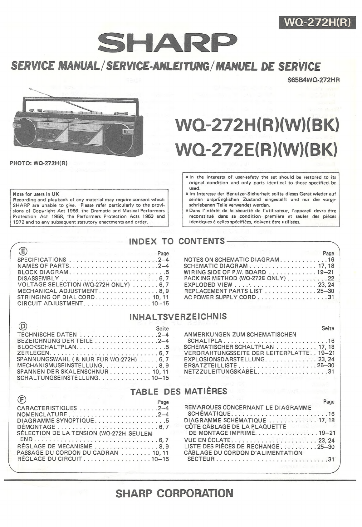
PHOTO:
WQ-272H(R)
Note
for
users
in
UK
Recording
and
playback
of
any
material
may
require
consent
which
SHARP
are
unable
to
give.
Please
refer
particularly
to
the
provi-
sions
of
Copyright
Act
1956,
the
Dramatic
and
Musical
Performers
Protection
Act
1958,
the
Performers
Protection
Acts
1963
and
1972
and
to
any
subsequent
statutory
enactments
and
order.
S65B4WO-272HR
WOQ-272H(R)(W)(BK)
WOQ-272E(R)(W)(BK)
@in
the
interests
of
user-safety
the
set
should
be
restored
to
its
orignal
condition
and
only
parts
identical
to
those
specified
be
used.
@
Im
Interesse
der
Benutzer-Sicherheit
sollte
dieses
Gerat
wieder
auf
seinen
ursprunglichen
Zustand
eingestellt
und
nur
die
vorge-
schriebenen
Teile
verwendet
werden.
@
Dans
I'intérét
de
la
sécurité
de
I‘utilisateur,
l'appareil
devra
étre
reconstitué
dans
sa
condition
premiére
et
seules
des
piéces
identiques
a
celles
spécifiées,
doivent
étre
utilisées.
INDEX
TO
CONTENTS
©)
Page Page
SPECIFICATIONS
.............
000000
eee
ee
2-4
NOTES
ON
SCHEMATIC
DIAGRAM.............
16
NAMES-OF-PARTS:;
5
cee
e-00
ern
ereecbarae
es
2-4
SCHEMATIC
DIAGRAM
................05.
17,
18
BLOCK
DIAGRAM..........
0.0000
c
eee
eee
5
WIRING
SIDE
OF
P.W.
BOARD
.............
19-21
DISASSEMBLY
.............0
000
eee
ee
cee
6,7
PACKING
METHOD
(WQ-272E
ONLY)...........
22
VOLTAGE
SELECTION
(WQ-272H
ONLY)
.......
6,7
EXPLODED
VIEW...
0...
cee
eee
23,
24
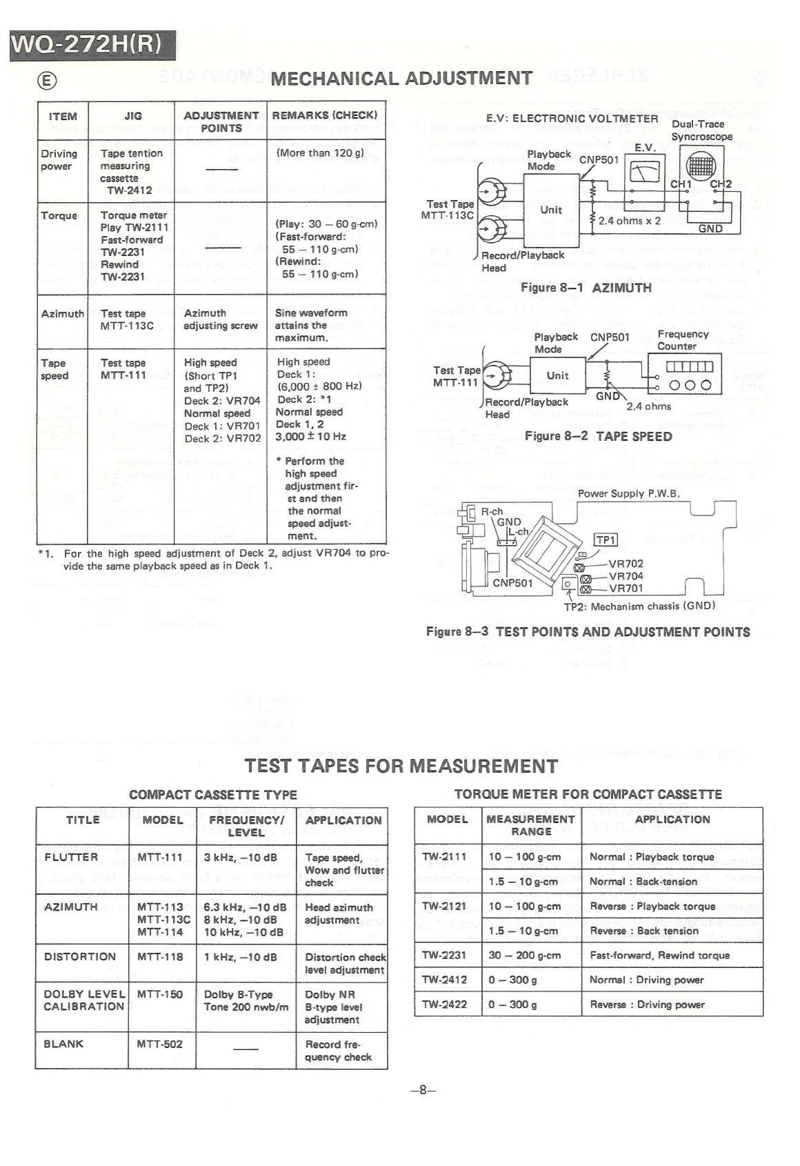
MECHANICAL
ADJUSTMENT................
8,9
REPLACEMENT
PARTS
LIST
............5.
25—30
STRINGING
OF
DIALCORD...............
10,
11
AC
POWER
SUPPLY
CORD.............00
0005
31
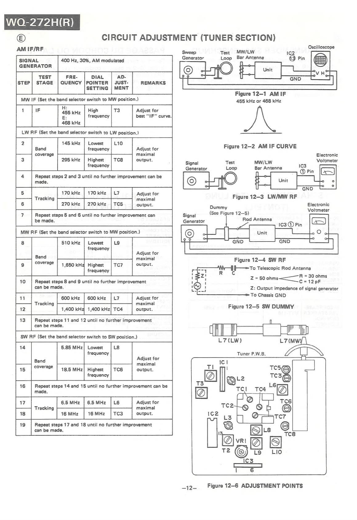
CIRCUIT
ADJUSTMENT...............00.
10-15
INHALTSVERZEICHNIS
©
Seite
Seite
TECHNISCHE
DATEN
...............020005
2-4
ANMERKUNGEN
ZUM
SCHEMATISCHEN
BEZEICHNUNG
DERTEILE.................
2-4
SCHALTPLAS
5.4
arts
ep
dmasasaneace
eaeens
16
BLOCKSCHALTPLAN...........
00000
e
sees
5
SCHEMATISCHER
SCHALTPLAN
...........
17,
18
ZERIGEGEN:
oaiises
heb
wee ONT
Aa as
ie
ORAS
6,7
VERDRAHTUNGSSEITE
DER
LEITERPLATTE.
.
19-21
SPANNUNGSWAHL
(
&
NUR
FUR
WO-272H)
.....
6,7
EXPLOSIONSDARSTELLUNG..............
23,
24
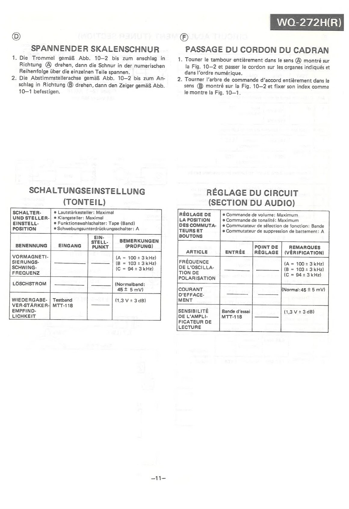
MECHANISMUSEINSTELLUNG...............
8,
ERSATZTEILLISTE..
2...
ee
es
SE
25—30
SPANNEN
DER
SKALENSCHNUR...........
10,
11
NETZZULEITUNGSKABEL...............0005
31
SCHALTUNGSEINSTELLUNG..............
10-15
TABLE
DES
MATIERES
©
Page
Page
CARACTERISTIQUES
................2.00.
2-4
REMARQUES
CONCERNANT
LE
DIAGRAMME
NOMENCLATURE
«ooo.
ecw
ene
ee
ee
ees
2-4
SCHEMATIOUE,
oUt
seceeeeesecupeacreeres
DIAGRAMME
SYNOPTIQUE...................
5
DIAGRAMME
SCHEMATIQUE
.............
DEMONTAGE
vstccce
a
fps
nce
Teepe
wn
wed
6,7
COTE
CABLAGE
DE
LA
PLAQUETTE
SELECTION
DE
LA
TENSION
(WQ-272H
SEULEM
DE
MONTAGE
IMPRIME.................
END.
..
£45
1
esa
ee
ook
pe
eae
ene
ems
6,7
VUE
ENECLATES
23
02254
SI
es.
REGLAGE
DE
MECANISME
.................
8,9
LISTE
DES
PIECES
DE
RECHANGE:
2:22.22...
PASSAGE
DU
CORDON
DUCADRAN
........
10,
11
CABLAGE
DU
CORDON
D’ALIMENTATION
REGLAGE
DUCIRCUIT..................
10—15
SECTEUR
..03
04
ecu
ccasw
esa
a
SRSaeeE
ES
SHARP
CORPORATION