o
o
RECORDING
Set the switches and controls as follows before you switch the power on.
o Set the TIMER START switch to OFF.
o Set the INPUT controls to the leftmost position (0).
o Inspect the head section for dirt. If dirty, clean it (Refer
to page 11).
. Set up the program source (records, FM broadcast,
microphone performance, etc.) which you intend to
record-
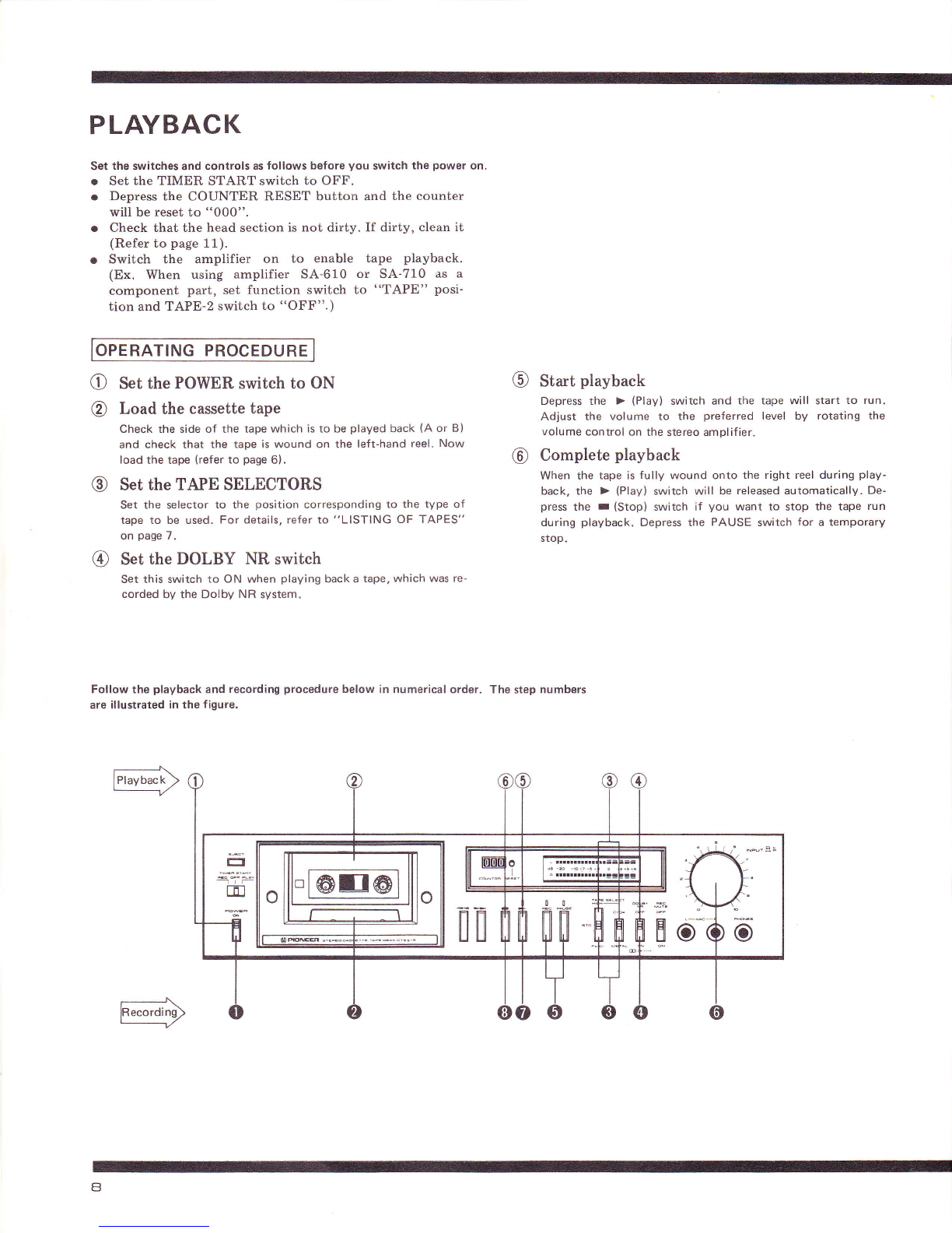
OPERATING PROCEDURE
O Set the POWER switch to ON
O Load the cassette tape
Check that the tape is wound onto the left reel, and load
securely. Also check that the erasure prevention tabs on the
cassette tape have not been broken off (see page 5).
@ Set the TAPE SELECTORS
Set the selector to the position corresponding to the type oi
tape to be used. For details, refer to "LlsTlNG oF TApEs,,
on page 7.
Set the DOLBY NR switch
Set this switch to ON for recording using the Dolby NR sys-
tem-
Recording standby
Depress the PAUSE and REC switches together. The REC and
PAUSE indicators both light. When a leader tape is attached
to the actual cassette tape, depress the > (Play) switch for
about 10 seconds to allow it to clear the heads before depress-
ing the PAUSE and REC swirches.
Depress the counter reset button and reset to "000".
"Leader tape": This is a section of the tape at the
beginning and end of the tape which
cannot be recorded.
Set the recording level INPUT controls
Refer to following the section on "SETTING THE RECORD-
ING LEVEL", and then adjust the INPUT controls.
Starting the recording
Depress the > (Play) switch. The tape now starts to run and
the recording begins. Observe the level meter occasionally
during recording to check the recording level and check the a-
mount of tape left.
Complete recording
When you have finished recording, depress the r (Stop) switch
and stop the tape. Depress the PAUSE switch for a temporary
stop. When the tape is fully wound onto the right reel during
recording, the recording mode will be automatically released.
TJIONEER
SETTING THE RECORDING LEVEL
Setting the recording level incorrectly and then
recording a program source can lead to a deteriora-
tion in the signal-to-noise ratio and to distortion. If
you are recording a program source with relatively
high signal levels, adjust the recording level con-
trols so that the meter display flashes across a
-sdB to OdB range.
o If you record sound where the meter display
registers a maximum input level of over +8dB,
the playback sound will be distorted, and con-
versely, if the level is too low (-20dB to
-10dB), the signal-to-noise ratio will be im-
paired and there will be a high noise level in the
playback sound.
o Depending on the program source, the signal
level undergoes wide-ranging fluctuations, and so
it is a good idea to keep an eye on the meter
indication while you are recording.
r- llll
dB -eo
R llll
lrl
USING THE REC MUTE SWITCH
Use this switch to cut out commercials during
FM broadcast recording, to create unrecorded
blanks between programs on the tape, to record
music from disks and to cancel out the noise
generated when the stylus descends onto the
disk.
1. Once one program has finished, depress the
PAUSE switch with the REC MUTE switch
held in the depressed position for about b
seconds. Once the tape has stopped traveling,
release the REC MUTE switch. The sound of
the program source can still be heard through
the speakers but it is not recorded on the
tape.
2. Depress the > (Play) switch when the program
source to be recorded is about to start. Now you
can record the program source again.
When recording music from a disk and the stylus
is about to descend onto the disk, depress the
REC MUTE switch and then release it just before
the music starts.
ERASING THE TAPE
r Recording onto previously recorded tape auto-
matically erases the earlier sound and replaces it
with the new program source.
o To completely erase a program, turn the INPUT
controls fully counter-clockwise and run the
tape in recording mode.
@
o
o
-eo -10 -7 -5 -3 0 +3 +5 +A
rrrrrrrtttlrttrrtlrr