COLUMBIA-BELL & HOWELL 355 User manual

-l
J
EI
=
o
E.
oII
Jrd
EH
i9
o-
=
3
J
o
I
PHoToFACT* FolJ"t
MIKE-RADIO
PHO
INPUT
TONE
CONTROL
ON-OFF
SWTCH
COIU'YIBIA.BELI & HOWEtt
moDEL 355
5PTTD
CHANGE
CONTROL
FORWARD
REWIND
AY
PEAKER
RECORD
RECORD
rocK
LEVER
fl
o
F
C
=
EF
EE
rF
Ep
t- o
{
llt
F
F
VOLUME
CONTROT INDICATORS STOP
Figure I
GENERAL INFORMATION
The Model 355 Columbia Bell & Howell Tape Recorder features Stop, Forward, Rewind,
Play, and Record modes of operation merely by pressing a button. A speaker push button is also
provided for monitoring programs or for using the recorder as a P. A. System. This recorder
is of the dual-track type, giving two full length recordings on a single reel of recording tape .
Any size reel up to 7" can be used. Two neon recording indicators simplify the recording level
setting. New recordings can be made on previously recorded tape Since the erase head is auto-
matically connected when the *Recordtf button is pressed or the same recording may be played
back indefinitely. Recordings can be made from a radio, television receiver, or phonograph ,
inaddition to those made directly from the microphone. fiecordings can be ptayed nack t[rougtr
the self -contained speakers or an external speaker may be connected through use of the Speaker
Jack.
Model 355 is designed to operate on 115 volts, 6U!, AC supply only.
CAUTION: Severe Damage Will Result If Connection Is Made To A Direct Current (DC) Line.
Columbia Records Inc.
?99 Seventh Avenue
New York 19, New York
fhis
w.. SAtvrs &
moleriol compiled ond published by
co., I NC., INDIANAPO IlS,
Copyright 1955 All Rights Reserved
INDIANA
DATI 10-55 srT 292
HOWARD
FOTDER {

':li,]!if:::l
tffj
ffi
Figure 2
SPECIFICATIONS Recording Time(?" reel)-
Reel Size- t hour at 7 1/2 ips. (/2 hour each track)
Up to ?". 2 hours at 3 3/4 ips. (1 hour each track)
Overall Frequency Response-
Tracks- ( Record To Playback At 7 L/2 ips. )
Dual. +2db from b0 to 10,000 cps.
Track Selection-
Manual turnover.
Tape Loading-
Drop-in-slot type.
Tape Speed-Play and Record-
7 VZ and 3 3/4 ips.
Fast Forward-
Distortion-
Less thdn 3% at 4 watts.
Power Output-
8 watts.
Wow and Flutter-
(At ? 1/2 ips. )
Less than 0.027o
Audio Inputs-
?" reel in g0 seconds. Microphone, Radio, Phono, TV.
Fast Rewind- Audio Output-
?" reel in g0 seconds. (a)Internal or Extension Speaker.
(b)External Amplifier.
sPeakers controls-
2 electrostatic "tweeters".
2-8" low-frequency "Woofeis". 3 knobs, 6 electric pushbuttons.
Page 2

Figure 3
fi
o
F
c
=
EF
EE
ll
8r
tro
{
EI
F
F
OPERATING INSTRUCTIONS
Making Connections-
Turn the "tone" control to the left to .'Offil and
plug the power cord into a convenient wall outlet of the
proper rating.
Threading The Tape-
With the "Stop" button depressed, place an empty
reel on the right hand (take-up) spindte. place a full
reel of tape on the left hand (supply) spindle so that
the reel will turn counterclockwise when tape is pulled
from the reel. Make certain that the reei springs on
the spindles engage one of the slots in the nufs of tne
reels and that the reels are fully seated. Reel out
about two feet of tape and feed the loose end up into
the empty reel on the right spindle. Thread the tape
into one of the slots in the outer surface of the hub.
HoId the loose end between the fingers and slowly ro-
tate this reel counterclockwise through a couple of
revolutions. While takingup slack in thetape between
the two reels the tape will automatically drop into the
tape slot.
To Record From Microphone-
1. Insert tne microihone plug into the ,,Mic. -
Radio-Phono" input jack.
2. Turn the "Off -Tone-On" control to the right
until a click is heard and allow approximately 30
seconds for the unit to warm up. "power on" condi-
tion is indicated by indirect illumination of the lucite
knobs from behind the front panel.
3. Unlock and push the "Record" button. Ob-
serve the "Record Level" indicator lamps while speak-
ing into the microphone. Occasional flickering of the
"Distortion" lamp indicates a good, high level of re-
cording, however, continuous glowing or flashing in
this lamp indicates that the "Volume" control setting
must be reduced. Be sure that the "Normal" lamp
glowsfairly full and steady oryou may not be record-
ing properly, if at all.
NOTE: The "Tone" control is inoperative when re-
cording.
Mic. -Radio-Phono Input-
This two-circuit, front-panel input jack provides
a 220,000 ohm high-impedance input for the micro-
phone and a low-impedance input for recording from
a radio, phonograph or TV set. A two-conduetor at-
tachment cord is supplied in the storage compartment.
This cord is terminated at one end with a jack plug
and at the other with two alligator clips to enable you
to make connection to various equipment for record-
ing or monitoring.
Page 3

Figure 4
To Record From_Racllg
@1. Take the radio-phono attachment cord from
the storage compartment.
2. Turn off power to the recorder.
3. With the two alligator clips on the end of the
radio-phono attachment cord, connect across the am-
plifier output or voice coil on the speaker of the radio,
phono, or TV set.
4. Insert the plug of the radio-phono cord into
the Mic. -Radio-Phono input jack on the front panel of
the recorder
5. Proceed with the recording as described in
"To Record From Microphone".
Double -Track Re cording-
The Columbia-Bell & Howell is designed so that
onty 1/ 2 the tape width is recorded at a time, there-
by resulting in double-track recording. This double-
tracl< operation is accomplished in the following
manner:
1. After a reel of tape has been recorded, i. €.
all the tape wound on to the take-up reel, de-
press the "Stop" button. This stops all move-
ment of the tape.
2. Remove the reels from the recorder, turn-
ing the full reel over and placing it on the left
Page 4
spindle and the empty reel on the right spindle.
3. Properly thread the tape and proceed with
the recording.
4. After the second track has been recorded
thefirst track isready to be played, without re-
winding, as follows:
(a) Place the full reel of tape on the left spin-
dle and the empty reel on the right spindle.
(b) Thread the tape making sure the dull side
faces the play-record head.
(c) Set the controls as described under "To
Play A Recording".
To Play A Recording-
1. Thread the tape as described under "Thread-
ing The Tape".
2. Turn the "Off-Tone-On" control to the right
and allow about 30 seconds for warm up.
3. Depress the "Play" button until it is latched
into position.
4. Adjust the "Volume" and "Tone" controls for
desired level.
To Edit And Splice Tape-
NOTE: Since it is impossible to edit and splice one
track without affecting the other, recordings

'
which are to be edited should be limited
one track only.
Figure 5
to Fast Forward And Fast Rewind-
fr
o
F
e
-
;F
EE
r-
8p
tt o
{
ltt
F
F
1. The tape may be edited by cutting out un-
wanted portions, or by joining selections into another
sequence. Announcements may be inserted between
selections, etc. Unusedsections of tape can be spliced
together for re-use.
(a) Cut tape at 600 angle with an overlap so
ends will line up. (Cutting tape at G00 angle
will eliminate detection of splice on record-
ing. )
Align both ends of tape, with glossy side
(c) Cover aligned ends with spticing tape,
evenly and securely.
(d) Trim off excess spticing tape. (Cut into
the recording tape very slightly. ) ttris elimi-
nates possibili[y of a sticky splice.
To Use External Speaker-
Any size speaker of the permanent magnet type,
having a 3,2 ohm voice coil, may be used by connect-
ing the alligator clips of the radio-phono cord across
the voice coil of the external speaker and then insert-
ing the radio-phono cord plug (same type as speaker
plug) into the "Speaker" jack.
High-speed forward or rewind can be obtained
by pressing the desired button. These functions are
used primarily in locating a desired portion of a re-
cording in a few seconds. You may press the "For-
ward" or "Rewind" button while in "Play" or "Record"
positions butyou cannot switch to otherfunctions until
you have first pressed the "Stop" button.
IMPORTANT: When pressing the "Stop" button. . . hold
it down until the reels come to a com-
plete stop.
To Use Recorder As A
@-
To operate this recorder as a public address
unit, insertthemicrophoneplug into the "Mic. -Radio-
Phono" inputand turn the power on. At the back of the
amplifier move the "Tape Drive" switch to "Off". Un-
lock and press the "Record" and t'Speaker" buttons .
While speahing intothe microphone adjustthe "Volume"
and "Tone" controls to the desired level.
The public address program may be recorded
by leaving the "Tape Drive" switch in the 'rorlrr posi-
tion. Then, proceed with the program as described
above.
(b)
trP.
Page 5

i
I
I
.*-
J
Figure 6
Program Indicator-
This odometer- type indicator registers "000"
to "999" and will save much guesswork when trying to
locate a desired portion of a pre-recorded tape. The
reading of the indicator may be noted as the recording
is being made so that reference to any given point on
the tape may be made very rapidly. When a recorded
tape has been so logged or referenced, always "zero"
the indicator before starting to play the recording.
This should be done before tape is threaded ori the
take-up reel. Press t}te "Forward" button and ob-
serve the indicator. Use the "Stop" button when ap-
proaching "000" and then the last few digits can be
turned off manuatly by spinning the take-up reel with
the fingers.
Speed Change-
This recorder operates at two speeds -7 l/2 or
3 3/4 inches-per-second. The "Speed Change" knob
will enable you to play or record tape at either speed.
For 3 3/4" operation, take hold of the knob and turn
it gently to the left, pull out, and release. To restore
the setting to 7 7/2", take hold of the knob as before,
turn it gently to the left, push in, and release.
ADJUSTMENTS
PIay/Record Head Adjustment-
It is very important that p 1a y - record head (9)
be lined up perfectly with the tape. If it is not, Iow
Page 6
output, loss of high frequencies or track overlap may
result.
IMPORTANT: The heads have been aligned and locked
in place at time of manufacture and
should require no further adjustment ,
unless it becomes necessary to install
a new head.
Toadjust, makeatape recording of a 3000 cycle
signal on a good unit. Place this on the unit that the head
is to be aligned on. Connect an output meter or AC volt-
meter across the speaker voice coil. PIay the 3000
cycle tape, rock play-record head (9) back and forth ,
Iooseningtwoscrews (1) will aliow you to do this, and
notice a variation in the output voltage at the voice coil .
Tighten screws (1) in the position of highest output.
Figure ?

In Brakin
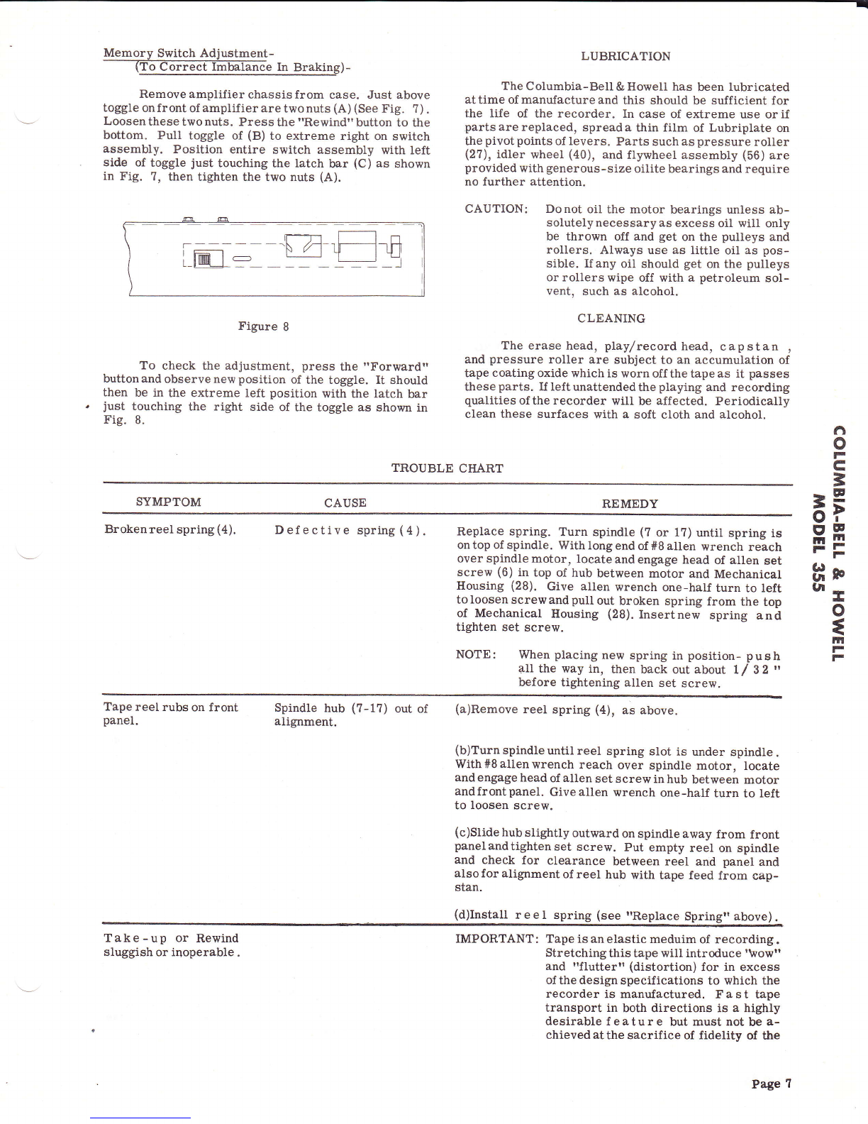
Remove amplifier chassis from case. Just above
toggle onfrontof amplifier are twonuts (A) (See Fig. ?).
Loosen these two nuts, Press the "Rewind" button to the
bottom. Pull toggle of (B) to extreme right on switch
assembly. Position entire switch assembly with left
side of toggle just touching the latch bar (C) as shown
in Fig. ?, then tighten the two nuts (A).
LUBRICATION
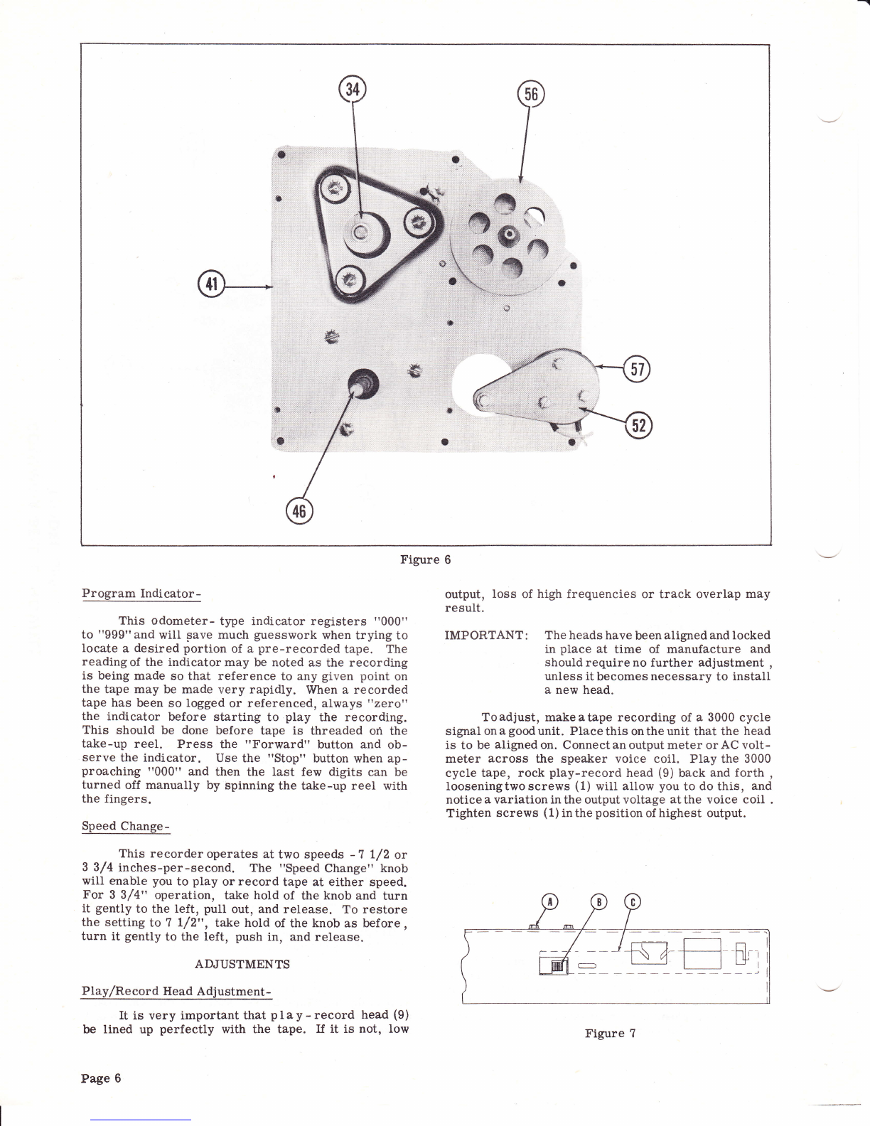
The C olumbia-Bell & Ilowell has been lubricated
attime of manufactureand this should be sufficient for
the life of the recorder. In case of extreme use orif
parts are replaced, spread a thin film of Lubriplate on
the pivotpoints of levers. Parts such as pressure roller
(2?), idler wheel (40), and flywheet assembly (56) are
provided with generous-size oilite bearings and require
no further attention.
CAUTION: Donot oil the motor bearings unless ab-
solutelynecessaryas excess oil will only
be thrown off and get on the pulleys and
rollers. Always use as little oil as pos-
sible. Ifany oil should get on the pulleys
or rollers wipe off with a petroleum sol-
vent, such as alcohol.
CLEANING
The erase head, play/record head, capstan ,
and pressure roller are subject to an accumulation of
tape coating oxide which is worn off the tape as it passes
these parts. If left unattended the playing and recording
qualities of the recorder will be affected. Periodically
clean these surfaces with a soft cloth and alcohol.
l-m= --M-E---'n
Figure g
To check the adjustment, press the "Forward"
buttonandobservenewposition of the toggle. It should
then be in tlre extreme left position with the latch bar
just touching the right side of the toggle as shown in
Fig. 8.
TROUBLE CHART
SYMPTOM CAUSE REMEDY
Brokenreel sprine (4). Defective spring (4). Replace spring. Turn spindle (7 or 17) until spring is
ontop of spindle. Withlongendof #8 allen wrench reach
over spindle motor, locate and engage head of allen set
screw (6) in top of hub between motor and Mechanical
Housing (28). Give allen wrench one-half turn to left
to loosen screw and pull out broken spring from the top
of Mechanical Housing (28). Insertnew spring and
tighten set screw.
NOTE: When placing new spring in position- push
all the way in, then back out about t / gZ "
before tightening allen set screw.
fl
o
F
c
=
EF
EE
8r
tEo
{
tn
F
F
Tape reel rubs on front Spindle hub (?-17) out of
panel. alignment. (a)Remove reel spring (4), as above.
(b)Turn spindle until reel spring slot is under spindle .
With#Sallenwrench reach over spindle motor, locate
and engage head of allen set screw in hub between motor
andfrontpanel, Giveatlen wrench one-half turn to Ieft
to loosen screw.
(c)Slide hub slightly outward on spindle away from front
panelandtightenset screw. Put empty reel on spindle
and check for clearance between reel and panel and
alsoforalignmentofreel hub with tape feed from cap-
stan.
(d)Install reel spring (see rReplace Springl above)
Take-up or Rewind
sluggish or inoperable .IMPORTANT : Tape is an elastic meduim of recording .
Stretching this tape will introduce '\vowrr
and "flutterr'(distortion) for in excess
of the design specifications to which the
recorder is manufactured. Fast tape
transport in both directions is a highly
desirable feature but must not be a-
chieved at the sacrifice of fidelity of t}e
Fage ?

TROUBLE CIIART Con't.
SYMPTOM CAUSE REMEDY
recorded tape For this reason the'take
offil must be a gentle action with po-
sitive control of the transport function
particularly at the ends of the tape.
NOTE: Afull?r'reelof1200feetof tape can be trans-
portedineit}erdirectioninabout 40 seconds .
Due to the gentle takeoff action a slight manual
assistance may be necessary to start the
reels. By this means positive control is main -
tained andthetape maybe repositioned at any
point withgreataccuracyandwithno I oss of
overall fidelity.
Takeup or Rewind
sluggish (continued )1. Low supply voltage.
2. Drive Belt (59) between
take-up motor and PRO-
GRAM INDICATOR odo-
meter pulley is too tight.
3. Defective odometer.
4. Spindle motor bearing
out of Alignment due to
rough handling during
shipment.
1. C heck line voltage. Shouldbebetweenl0Sand 125
volts AC.
2. Stretch drive belt (59) slightly.
3.Removedrivebelt (59) from odometer pulley (64) and
turn pulley with fingers through several revolutions. If
pulley does not turn freely at any point of revolution
replace odometer.
4. Tap end of spindle sharply with wooden or p I a s t i c
handle oi screwdriver.
Tape speed erratic. 1. Capstan drive slipping
due to oil or dirt on drive
surfaces.
2. Tape wound around cap-
stan; oil or dirt on pres-
sure roller.
1. Cleandrive surface using a small lintless, soft cloth
(cheesecloth or equival ent ) dipped fightly in carbon
tetrachloride, alcohol, orlighter fluid. With drive run-
ning, hold cloti against motor drive wheel (34), idler
wheel (40), and capstan flywheel (56).
2.Removetwo screws in front or recording-head cover
plate (5). If tape is wound around capstan peel or cut
it off.
CAUTION: Be extremely careful not to scratch or
mar surface of capstan. Use soft clotlr
dipped in carbon tetrachloride, alcohol ,
orlighterfluid to clean surface of cap-
stan and pressure roller. Use pipe- stem
cleaner dipped lightly in one of above
f luids to wipe off any tape dust from
face of brush rfredheadst'.lteplace cover
plate and screws,
NOTE: Do not turn screw in too tightly.
Hum in playback 1. Congested wiring. 1. Separate wires in back of recorder to make certain
none comes against moving parts, Check tlat all plug-
inconnectionsaresecurelyin place. Reverse the power
cord plug in wall socket.
2. P r e s s "PlAY"button and set "VOLUME" for pre-
ferred listening level. Place *SPEED CHANGE" knob
in "NEUTRAL" (between the 3 3/4 and 7 l/2 ips. ) Hum
shoulddisappearindicatingtoo low an input signal lever
was used for recording. Set proper input level when
recording.
NOTE: It should never be necessary to raise the
*VOLUMEIT control setting above il3tt ort4tt
when recording. If hum persists observe the
following:
2. Recorded signal lever
too low.
Page 8

TROUBLE CHART - Con't.
SYMPTOM CAUSE REMEDY
3.AC hum piekup from
power equipment (trans-
formers), fluorescent
fixtures, etc.
4. IIum pickup from assoc-
iated signal equipment
5. Defective vacuum tube .
3. Avoid operating the recorder in the proximity of such
devices and,/ or provide a good electrical ground for the
amplifier chassis.
4. (a)Switch input connections. (b)Provide a common
metallic bond between all associated equipment and
ground system securely.
(c)If signal output voltage of associated equipment is
characteristically low use shielded lead between signal
source and recorder input.
5. Check and replace faulty tube.
Does not
perly. erase pro- Pressure Pad Worn. Remove recording-head cover plate (5) and examine
felt pad on pressure levers. Replace if worn. Peel off
old pads and mount new ones (from envelope stapled
in Instruction book) using Du Pont clear cement or
equivalent.
Does not
perly. record pro- 1. Faulty operating pro-
cedure.
2.Pressure pad worn.
3. Distorted r e c or d ing.
l.Refer to rrOperating Instructions'r. Also observe
I'REMEDYil column under ilEum In Playbackr of this
chart.
2. Examinefor worn pads and replace if necessary (see
replacement directions above).
3. Try recording with microphone supplied with the re-
c o r d e r . If clean recording can be made with .mikerr
check for mismatched impedance in hookup of associated
equipment.
6
o
F
c
3
>2
6f
HE
Er
gr-I
o
{
m
F
F
Page 9

#ll
I
#w
6
&
ei
rr l|]
*-,\i Il
Figure 94. ExpLoded View Of Parts Above Baseplate.
Page 10

fI
o
F.
G
3
EF
EF
II
HF
n,tt
o
{
hil
F
F
A PHOTOFACT "EXPLODED" VIEW
@ Howard W. S"mr & Co., lnc. 1955
€
e6
t-
@
lra.,
6#
@
Figure 98. Exptroded view of parts Below Baseplate.
Fage 11

Figure 10
@20
5W @20 t>
5W
TO TWEETER
SPEAKERS
TO PIN5OF V5
TO C20 - Czt
TO SPEAKER JACK
TO R29 OTJTPUT
TRAHSFORM€,R
El rr5tr--|-trgr.
{0f {fr {o0U{f
l5O.cr ZOW
PIN l AND 2 OF POWER TRAI.iS.SOCKET
SUPPLY
MOTOR DRIVE
MOTOR
A PHOTOFACT STANDARD NOTATION SCHEMATIC
@ Howard \7. Sams & Co., lnc. 1955
TAKE UP
MOTOR
AC \ryIRING DIAGRAM
Page Lz

f)
o
F
C
=
6P
EE
r;r
8F
uE
o
t
H
F
F
-fr
FEs
;; *s
+@o EH
+ r-^nfv- f;z
lu H l@^l'
,
@ @a I -E I
Pa;'--nAAr-
ez@
=<
uS
=<
'@
N
=s
<ao
@
ofl
N:
+
@
{
_.1
\
=/-
+
@
@
+
L
o
U
:
@e*esili f
$
I
C\J
O)
CU
I
hu
rtx
tz
t;
t-
!r'q3
@
o
a
{F-1r,
;@
@
o
N
or
@
L
o
9
\
f
ET
@
o
fi at
E>
*l.' e
@
Y
o
F
!t
@
@
nB Es
o>
,S'gE
F:
lHl''
@
3
o
o
@
N
c(
=s
t<
e
o o
t4
Nc
|!
E
TFr
E
@fHe
Page 13

ffi
ffi
ffi
Figure 11
Figure 12
trage 14

EI,ECTRICAL PARTS LIST
Ref.
No. Part
No. Description Ref .
No. Part
No. Description
tvl
lv;
lv+
lvs
lvo
lut
lclA
lclB
lcrc
lcrn
lcz
lcs
lca
l::
lc?
lca
l"n
tc10
lc-rr
I c-n
I c-rs
I c-ra
I c-rs
I c-ro
I c-rz
lc-re
I c-rg
I c-zo
I c-zr
I c-zz
I c-23
I c-z+
I c-25
lc-zo
I C-27
c-281
c -291
cro I
c31 |
crz I
ces I
Rl I
R2 I
R3 I
R4 I
RsI
R6 I
R?I
R8 I
*?. I
*tt {
I e8-28
I e8-15
t98-24
I se-rz
l 98-12
98-12
98-8
98-20
98-23
98 -14
99-35
99-64
99 -3
99-2
99-1
99-6
99 -7
99 -60
99 -10
99 -39
99-1
Igs-z
lss -z
lsg -s
lss-+
ln:l
l,ll,
I se-zo
lsa- r s
lge-rs
lge- re
lse-ro
198- 1?
lss - rs
lse-z
lss- rs
lga-e
I ss-a
I gs-z
I se-z
I sa-zo
I ss-a
I sa-e
I 98-12
I sa-a
lge-zz
I ss-rs
I ss-zs
1ZAT?, Pre-Amp.
12AT?,AF Amp.
I?AVT,Phase Inv. & Record Amp.
6AQ5, Output
6AQ5, Output
12AU?, Oscillator
5Y3GT, Rectifier
Elect. Cap. ,20MFD. @450V.
Elect. Cap. , 20MFD. @4b0V.
Elect. Cap. ,20MFD. @)450V.
Elect. cap. ,20MFD. @)450V.
Elect. Cap. , 25MFD. @ 50V.
Elect. Cap. ,20MFD. @350V.
Elect. Cap. ,25MFD. @)OV.
Elect. Cap. ,20MFD. @350V.
Elect. Cap. ,25MfD. @6V.
Cap. Ceramic, 20, 000MMF. @ 1d%
Cap. Ceramic, 390MMF. @ b00V.
Cap. Ceramic, 10, 000MMF. @ 500V.
Cap. Ceramic,20, 000MMF. @ 1@6
Cap. Ceramic, 10, 000MMF. @ 10%
Cap. Ceramic, 2, 000MMF. @ Lqo
Cap. Molded, . 05MFD. @400V.
Cap. Ceramic, 20, 000MMF. @ 10%
Cap. Ceramic, 20, 000MMF. @ Lqo
Cap. Paper Tub. , . 05MFD. @ 1b0V.
Cap. Molded, . 05MFD. @400V.
cap. Motded,. 05MFD. €)400V.
Cap. Mica, 100MMF. @1(%
Cap. Molded Paper, . 05MFD@[00V.
Cap. Molded Paper, . 01MfD@ 400V.
Cap. Ceramic, 10,000MMF. @b00V.
Cap. Ceramic, 5, 000MMF. @ 1ffiNot
used in all Models)
Cap. Molded Paper, . 1MFD. @ 1b0V.
Cap. Ceramic, 10,000MMF. @b00V.
Cap. Mica,200MMF. @1d6
Cap. Mica, 100MMF. @Lqo
Cap. Mica, 100MMF. @ 107o
Cap. Mica, 100MMF. @1006
Cap. Molded Paper, . obMfD. @400V.
Cap. Molded Paper,.05MFD. @lbov.
Cap. Paper Tub. , .2MFD. @600V.
Elect. Cap. ,40Mm. @350V.
Vol. Control, 500Kf,)
Tone Control, & Sw. ,250Ke
Resistor,4. ?Meg. @I/2 W.
Resistor, 2ZKS}/@-l/Z W.
Resistor, 220KO@ L/Z W.
Resistor, 10Meg. @l/Z W.
Resistor, 4?0Kfl€) 1 W.
Resistor, 1. 8Meg. @L/Z W.
Resistor, lMeg. @ L/Z W.
Resistor, 1. bKC@ L/Z W.
Resistor, 220KO@l/2 W.
R12
R13
R14
Rl5
R16
R1?
Rl8
R19
R20
R21
P"22
R23
P"24
R25
R26
R27
R28
R29
R30
R31
R32
R33
R34
R35
R36
R37
R38
R39
R40
R41
PL42
R43
F,44
R45
R46
R4?
R48
R49
R50
R51
R52
R53
R54
R55
T1
T2
M1
M2
M3
M4
M5
M6
M7
MR
I199-22
lss-zz
I ss-s
I ss-s
I ss-z
I ss-rr
I ss-ra
I gg-rz
I ss-z
I ss-aa
I gg-e
I sg-ss
I ss-as
I ee-1e
I ee-7
| 99-40
I ss-r+
I sg-zr
I ss-oz
I
I s9-10
I ss-ro
99-8
99-8
I
I ee-65
99-14
99-4 1
99 -65
99-1
99-1
99-22
99-20
99-56
99-41
99-43
99-42
99-33
99-29
99- 15
99-3?
99-3?
99-5?
99-5
99-?
99-11
130-3
130-4
01-1?
8?-61
8?-61
86-18
86-19
86-20
130-6
AA-''
I
Resistor
Resistor
Resistor
Resistor
Resistor
Resistor
Resistor
Resistor
Resistor
Resistor
Resistor
Resistor
Resistor
Resistor
Resistor
Resistor
Resistor
Resistor
Resistor
all model
Resistor
Resistor
Resistor
Resistor,
Resistor
Resistor
Resistor,
in all mo
Resistor,
Resistor,
Resistor,
Resistor.
Resistor,
Resistor,
Resistor.
Resistor,
Resistor,
Resistor.
Resistor,
Hum BaIi
Resistor,
Resistor,
Resistor,
Resistor,
Resistor,
Resistor,
Power Tr
Output Tr
Pilot Lan
Neon Lar
Neon Lan
Play-Rec
Memory I
Tape Drir
Selenium
Push Butt
, 33K0(D 1/2 W.
,33Kfi€)1/2 W.
,2.?KSl@r/2 W.
,100K0@)1/2 w.
,22KS@ r/2 W.
,82Ka@)1/z w.
,10Kfi€)1/2 W.
,4?0KS2€)r/2 W.
,22K{@t/2w.
,1Kc@1/2 w.
, 100K@ L/2 W.
,47A@L/2 w.
,47Kr,7@r/2 w.
150C,@)1W.
4?0Ko@)t/2 w.
330A€)2 W.
10Ke€)1/2 W.
1oo€)2w.
22s1@2W.(Not used in
.s)
1Meg. @1/2 w.
150K0@1/2 W.
100Kc€)r/2 w.
100K0@)L/2 W.
3.3Meg. @L/2 w.
1oK0€)1/2 W.
4.7Ks)@t/2 W.(Notused
lels)
3. 3Meg. @t/2 w.
220KC€)r/2 W.
220Ke@r/2 W.
33KO@)1/2 W.
47K51,@t/2 W.
2.ZKQ@L/ 2 W.
4. ?Kf2@)1/2 W.
1K0@2 W.
2.2Ks,@2 W.
4. ?Ks@1 W.
4. ?O@1 W.
rnce Cont. ,100Q
20a@)5 w., w. w.
200@)5 w. , w; w.
50o€)30w. , w. w.
150f,@)20w. , w.w.
4?0Kf@ L/2 W.
82Ka@)L/2 W.
ansformer
ansformer
rp, TS4?
np, NE51, Normal Ind.
rp, NE51, Distorted Ind.
ord Slide Switch
iwitch Assy.
re Switch
Rectifier
on Swifch Assv
f)
o
F
c
=
EF
EE
'F
8r
tro
{
llt
F
F
MECHANICAL PARTS LIST
Ref .
No. Part
No. Description Ref .
No. Part
No. Description
1
2
3
4
5
6
I
3-2
63-1
61-34
188-10
188-24
4t-2
1 88-4?
Screw-Bd. Hd. #5-40 x.3/16
Washer-#5 Ext. Tooth
Washer- 9/64 x l/4 x .03L
Spring-Reel
Panel-Record Head Cover
Screw-Set #8-32 x L/4
Disc-Takeup Spindle
8
I
10
11
L2
13
14
15
11- 13
188-37
3-4
63 -4
130-202
130-246
130-330
130-273
Screw Rd. Hd. Thd. Cut#2-56 x /16
Record-Play llead
Screw-Bd. Hd.#6-32 x L/ 4
Washer-#6 Ext. Tooth
Tape Guide
Erase Arm
Erase Head Pad
Record llead Pad
Page 15

MECHANICAL PARTS LIST - Con't.
Ref.
No. Part
No. Description Ref .
No. Part
No. Description
16
t7
18
19
20
2l
22
23
24
25
26
27
28
29
30
31
32
33
34
35
36
3?
38
39
40
t30-247
188-46
188-38
82-1
130-209
355-2
188-6
130-282
82-7
130-207
130-264
130+{935
130-S- 1 1
13-1
188-15
130-206
18-22
130-231
130-296
t8-22
r30-212
130-2?8
130-211
130-263
Record and Play Arm
Disc-Rewind Spindle
Erase llead
E-Ring
Spring-Double Torsion
Nameplate Support
Nameplate- Logo
Escutheon Cabinet
Head Bracket
E-Ring
Washer-Pressure Roller
Roller-Pressure
Mech Housing
Counter Assembly
Screw-Bd. Hd. Self. Tap.#6-32 x l/4
Spring-Idler
Speed Changer Shaft Stop
Screw-Ilex Hd. Self T. #6-32 x i/LG
Drive Motor Pulley
Roller Plate Guide
Screw-Hex Hd. Self T. #6-32 x5/16
Speed Changer Shaft
Idler Crank
Idler Link
Idler Wheel
4t
42
43
44
45
46
47
48
4g
50
51
52
53
54
55
56
57
58
59
60
61
62
63
64
65
130-210
89-10
90-27
61 -39
18-25
90-29
188-58
188-52
130-201
130-285
18-23
130-S-46
1 30-323
130-240
1 88-63
1 3 -S-14
130-254
90-38
130-265
61 -9
130-S- 1 1
67-9
130-S-10
L30-252
130-S-43
Motor Mounting Plate
Shock Mount (Lord)
Drive Motor
Washer-3/ t6 x7/ 16 x . 032
Screw-Hex. Hd. SeIf T. #8-32 x l/ 2
Take Up Motor
Ean-4"(5/ 16 ID hub)Ventilating
Roller Plate Spring
Pressure Roller Plate
Rewind Motor Mounting Plate
Screw-Hex IId.Self Tap. #&32 x 5/16
Solenoid Arm & Pin Assembly
Hum Shield
Solenoid Link
Solenoid Link Spring
Flywheel Assembly
Solenoid
Rewind Motor
Counter Belt
Washer-Plain. 265 x L/2 x . 030
Counter Assembly
Spring Washer (3/16 x 3/8 x . 006)
Counter Worm Assembly
Counter Pulley
Counter Frame & Bearing Assy.
Page 16
Table of contents