Sharp 29RX5 User manual

29RX5
29F1X8
L
SX7i329RX5111
28 SYSTEM COLOUR TELEVISION
28
*IJ
~
*~
f!
~
~J\!;f-JL
Chassis
NOB
SP-71
MODELS
~
In the interests of user-safety (Required by safety regulations in some countries) the set should be restored to its
original condition and only parts identical to those specified should be used.
T,}
Tffl r-
*~;gm
(f[HJl-~1;:
OO,*89*~
J;~;f1HI9fifi~).
h'IL
itt
~
rJQ.
tJl1*
-to;fr
iRm
(j~J
~k:5
.iffi
11.
H
H~
1tJfj !'oj
ti17:E
~~
tEl
[OJ
89:g~
14:
0
CONTENTS
Page
•ELECTRICAL
SPECIFICATIONS
2
•
IMPOTANT
SERVICE
NOTES
3
•'ADJUSTMENT
PRECAUTIONS
4
•
SERVICE
ADJUSTMENT
12
•
TROUBLE
SHOOTING
TABLE
25
•
CHASSIS
LAYOUT
DIAGRAM 35
•PRINTED WIRING
BOARD
ASSEMBLIES
37
•
SCHEMATIC
DIAGRAMS
AND
WAVEFORMS
43
•
OVERALL
BLOCK
DIAGRAM 67
•
REPLACEMENT
PARTS
LIST 69
WARNING
The
chassis
in
this
receiver is
partially
hot. Use an
isolation transformer between the line cord plug and
power
receptacle, when
servicing
this
chassis.
To
preventelectric shock, do
not
remove cover. No user
-serviceable parts inside. Refer servicingto qualified
service personnel.
Jilfi
•
~J1t
FJIHfi··
.,........................................... ...... 2
•
1*
3'f
~1t
11~ifi:"
~
i.i:{f
~JiJI
................................... 3
•
iJlil~:Jb~"''''''''''''''''''''''''''''''''''''''''
4
.1:*~i~~
..··....·....·..·..·..........·....··..· · 12
•
Mcp!f~11~iJtEf£~"""""""""""""""""""""
25
• fILt;;
r~:&
eI'!J1t;(P"
~
, . 35
•
fnijlj
rt!.~%t&B~J~Jl~1t·
·.. 37
•
Lt!.~%fJj{J
ELECTRICAL SPECIFICATIONS
EE!..~~~
1\)1\)
lDlD
:Il::D
xx
COC1l
Et!.lli\
··············3i::liiE110-240V,
50/60Hz(
13
i'j;W~)
:w$li1ljEfj···
·..··•..·..· ·•••••·•·••··••··•·..···········•·...•••.•.••..•....•••.....•......•....•.•..
185W
~~
···········································I3~~~gjf.
~.s··············
..·..
·················
..
················
..
·························~Et!.UL,
~Et!.ULmtEt!.1t.S
39tl1i~~··················································
~i.li:~~
tp~
l?fl~tp~~1&:
38.0MHi·
P;'tl'tp~$'t1&:
6.
5MHz······
..····•······..································
31.5MHz
6.OMHz···················································.......•..•........•...................... 32.
OMHz
5.
5MHz
..···•·..··•..··..··· ..··..··········..··················· 32.
5MHz
4.5MHz
..•······················....····..,··..·..·······..····.......•..........•.....•............
33.5MHz
-@'~iJ~l&:
PAL/NTSC$J~····················································································33.
57MHz
SECAM$J~·
..···········································································33.594/33.
75MHz
NTSC$J~··························································································34.
42MHz
~lI\oJllJl5'E:~lli:w$·
..
•••••·••••••••••••
..
···•••·••••••
..
••••·•••
..
•••••••
..·····10Wx
2+13W=33W(Al*)
tmp;~
R-r
10cmrnll~
x 2,R, 10cm{iirtlbfIJa
'tl'1II~ll.tt·····
..······•·..·•·························..400Hzlt-tJJ8Q
.400Hz1t-tJJ5Q
({iirtm~H)
;1Cf&~;\.~ll.tt······································
..············································75Q
~F:ljZ1ti~
~®:~~
PAL-B/G,
SECAM-B/G$J~
il!i:il1Ii~VHF··············································································
..
····E2-E12~~
@il1Ii~UHF·················································
...•............................
E21-E69~~
11Jf&Et!.tl\!.CATV·········
..
·····································..............................
X-Z+2~~
Sl-S41~~
PAL-D/K,
SECAM-D/K$U~
il!i:il1Ii~VHF·········
..··············································•..
························R1-R12~~
Cl-C12~~
@il1Ii~UHF·················
..······..···..· ·..······
······
21-69~~
C21-C57~~
PAL-
I,
SECAM-
I$J~
il!i:il1Ii~VHF··
..······· ·················· ············..........
(~~~)
:
B-J~~
@il1Ii~UHF
..···· ··..·..·········....····· ·
··········
C5iH!!I,
w~)
:
21-69~~
NTSC-M$J~
il!i:il1Ii~VHF
..·..··· ..···....··..·..········..·····..........·..
·········
..·........
(~OO)
:
2-13~~
(8:$:)
:
1-12~~
@il1Ii~UHF··
..···•..•···..·····························..···..··...............
(~OO)
:
14-69~~
(8:$:)
:
13-62~~
1ff&Et!.tl\!.CATV
....·....·..
·······
..··..········....·......··..··....·········
(~OO)
:
A-6-A-1~~
A-W+29~~
(8:$:)
:
C13-C63~~
thru R12,
C1 thru C12
21 thru 69,
C21 thru C57
(IRELAND): B thru J
(U.K.,H.K.): 21 thru 69
(US): 2 thru 13
(JAPAN): 1 thru 12
..... (US): 14 thru 69
(JAPAN): 13 thru 62
(US): A-6 thru A-1
A thru W+29
(JAPAN): C13 thru C63
PAL-D/K, SECAM-D/K
VHF R
NTSC-M
VHF .
PAL-I, SECAM-I
VHF ..
CATV .
Receiving Frequency . 48.25 MHz thru 161.25 MHz
~~~
~~~.::::::::::::::::::::::::::::::::::::::::::::::::::::::::::::::::::::::::::::::::::::::::::::::::::::::::
:::
:
: :
:
;
3
~
~
i:
~
~
~
i~~~
~~~:~~
~~~
Power Input AC 110-240V, 50/60Hz (Auto)
Power Consumption 185W
Convergence Self Convergence System
Focus Bi-Potential, Uni-Potential Electroslatic
Sweep Deflection Magnetic
Intermediate Frequency
Picture IF Carrier y38.9 MHz
Sound IF Carrier
6.5 MHz 32.4 MHz
6.0 MHz 32.9 MHz
5.5 MHz 33.4 MHz
4.5 MHz 34.4 MHz
Colour Sub-Carrier
PAUNTSC 34.47 MHz
SECAM 34.494/34.65 MHz
NTSC 35.32 MHz
Audio Power Output Rating 10 W x 2 + 13W total 33W (Max)
Speaker
Size 10 em Round x z-pcs., 1OemWoofer Box
Voice Coil Impedance 8 ohm at 400 Hz, 5 ohm at 400Hz (Woofer Box)
Aeriallnpul
Inpedance 75 ohm Unbalanced
Receiving Channels
PAL-B/G, SECAM-B/G
VHF E2 thru E12
UHF E21 thru E69
CATV ..x thru Z + 2,
S1 thru S41
I\)
~®:~$
1~~il!i:il1Ii~VHF""''''''''''''''''''''''''''''''''''''''''''''''''''''''''''''''48.
25l1Hz-161.
25MHz
il1IiJ.$;~il1Ii~VHF"·"··"·"·"····"···"""""·""""·"·"·"··"·"····
168.
25MHz-431.
25MHz
@il1li~UHF""""""'""""""""''''''''''''''''''''''''''''''''''''''''
439.
25MHz-863.
25MHz
Specifications are subject to change without notice. I
..t~m..flt~:!:Z~ir,
~1'¥'fT~~
I
/'
'-',
/"
"
/-'-'~.
1'/
~',
-
.....

IMPOTANT SERVICE NOTES
!I
1.H'-·--·-·--~--~·-~-·-··--~---·-···--
--
.-
..
-----.
---
p.
1**tl{~]l[~l±~.~
**mm~_~R~~.n~*A~~ff.
Maintenance
and
repair
of
this
receiver
should
be
done
by
qualified
service
peronnel
only.
~m~.E~%ama~~mpz$.
*~~ITr~~~~~~.
l.~~%am~~~~~~~~~~&~Xm~~~Z~,
~m~~~~~~~m~~Z~
~x~~~~.
2.~~%am~~~~.*m.~~~~
•.
~~.~
•.
m.E~.~~H~«ft~.~
~~m~.
%m-%~~.~~~m~~~~.H.~~~~~
••
ft#.
*-=:F
~
EE
~
f@"C
;fj:llm:.
$.
W-
~
1*
ff
~
~
)l;j"i'lliBi.~~i!tIT~~~.at.
$'C~.II
ttl.
'ti''It
&*mw:St!j~=IIEt\t
51!5t~
Jil
~~!5t
(lifU~fJlj
~~<IT.)
I$lt->UOKO~~~1l.fi,
~~~~m~i'lliBi:~!(it~~'/Il>~.
(Z~tr.
m:b\.~l!Jjl
1lll~~iilll*m~~l!Jjl51~1ill~.
)
1.*
~mm.llttl.'It:>\l
!iHit
P"l
j:Un~lIl:lt.
2.
:>\I~liE*~amlV~-!ll!:Jil
~~~
•
.IIttl.'l1I'~J!~!lO'~-!ll!:m
jll]~%=I!f.
3.1ilI!~.II~'l1I'at.
::{'{itf1iJlV~~WJ:.tI!.
~.~IilI!~.IIttl.'l1I'.
~~$'Cm.~.c~
••
mw.~.
*A~%~a~~~E*ft~IT.
I
I
Iitl
{~
)§
Y=I
~
Z.
iVJ
II*-=FXM~
I
I
11*%mm:>\lX.M~lIl:lt.
~~.
ffWXM!5t~.It~~~.~~)l;j"t\tm
••
n.
aa~.
!~~~~~.at.
~*at~~
••
m~P"lmm~a.Z~~.
~~~~~~~*r~~~~
IXM!5t.M~~.:>\I~,
*~~Wr~mmm~:
Ill.
~.~Jl§*~amP"lw%~at.1fJ~lJ:~i'lliBi:~;i34.
OkV(~.:r*%~:>\IO
~
Aaj).
i2.
:>\I~liE*
~am~lE1tI.~.
g§-!lO'f*liE~i'lliBi::>\I29.0
kV
±1.
5kV
(%.:r*
~~:>\I1.
61llAat)
~I.~~~.
~I.~~~~~*~mmlllr$E~~~~~.
**%am-g~~.~Jl§.
~~~~J:.~I.~i'lliBi:~~~~~~~.
~~.
~.~Jl§%
~.
*~~~)l;j"~i'IIi$~~IT~~~~.
.J!~attl..at.
::{,~-!ll!:m.~~~~.::{'jll]r
••
::{'jll].~~.IIttl.
••
~.r~~~~~
~?l~XM~.M~~Jl&:.
I
I
..
!
.,.'
,
SERVICING OF HIGH VOLTAGE SYSTEM AND
PICTURE TUBE
When servicing the high voltage system, remove static charge from it by
connecting a 10k ohm Resistor in series with an insulated wire (such as a
test probe) between picture tube dag and 2nd anode lead. (AC line cord
ahould be disconnected from AC outlet.)
1. Picture tube In this receiver employs integral implosion protection.
2. Replace with tube of the same type number for continued safety.
3. Do not lift picture tube by the neck.
4. Handle the picture tube only when wearing shatterproof goggies and after discharging
the high voltage completely.
BEFORE RETURNING THE RECEIVER
Before returning the receiver to the user, perform the following safety
checks.
1. Inspect all lead dress to make certain thatthe leads are not pinched or that hardware is not
lodged between the chassis and other metal parts in the receiver.
2. Inspect all protective device such as non-metallic control knobs, tnsulatinq fishpapers,
cabinet
backs,
adjustment
and
compartment
covers
or
shields,
isolation resistor-
capacity networks, mechanical Insulators etc.
X-RAY
This receiver is designed so that any X-Ray radiation is kept to an absolute
minimum. Since certain malfunctions or servicing many produce potentially
hazardous radiation with prolonged exposure at close range, the following
precautions should be observed:
1. When repairing the circuit, be sure not to increase the high voltage to more than 34.0 kV
(at beam OIlA) for the set.
2. To keep the set in a normal operation, be sure to make it function on 29.0 ±1.5kV (at
beam 1.6
mAl
in the case of the set. The set has been factory-Adjusted to the above
mentioned high voltage.
...If there is a possibility that the high voltage fluctuates as a result of repairs, never
forget to check for such high voltage after the work.
3. Do not substitute a picture tube with unauthorized types and/or brands which may cause
excess X-Ray radiation.
i
i
(,,)
·11
It
I .
=----------.-----.-.---.--._-
..
1\)1\)
<c<c
:0::0
XX
ooc.n

J::o
ADJUSTMENT PRECAUTIONS
This model's settings are adjusted in two different ways: through the I'C bus control and in the conventional analog
manner. The adjustment via I'C bus control include present-only variable data.
1) Calling the service mode by the
microprocessor
G)Make a short-circuit between TP1001 and TP1002, and the microprocessor is put in the service mode (adjust-
ment through the I'C bus control).
® Perss the CH-DOWN key on the remote controller to get ready to select the modes one by one.
@Perss the CH-UP key on the remote controller to get ready to select the modes in order opposite to the avove
step
®.
@Using the VOL UR keys on the remote controller, the data can be converted.
@Removetheshort-circuitbetweenTP1001
and TP1002, and the microprocessor is put out of the service
mode.
2) Setting the initial (preset) values
G)Call up the service mode and turn on the main power switch. Anew E'PROM Uudgedby the first 4bytes) can
be automatically set to the initial data.
®The
initial data 'ire as shown on pages 8,9,10 and 11.
@Note that some items of the data must be modified and the others must stay as initial.
NOTE: Afterthe chassis has been assembled, be sure to call up the service mode first and then turn on the
main
power
switch, as discussed in 2-G)above. If the main
power
switch is turned on without the
E'PROM initialized, an excess beam current may
flow
into
the circuitry.
"'l.fflJ
~
13-.::t
~
JS:
$=
::gl{
*~-I9'tt.m~
EB
I2C~~~$<J!;-All;~~ll;(VI4"PJ;r,1f';l£ff.
I2C~~~$<Hgj'!1YJ!lIlN:lE:
0]1(
N:)~~r~~~t~~~§~VI4~N:lE:.
1)
il(HJ:!JI!fJLi¥J1*~iJlij~:/ji;~i¥Ji51::@:
CD~iHtTPlaal~TPlaa2zi6],
1!I.i:jtl;!JI!fJL!lP!l.l:'f1UFiJlij~:/ji;~
(I'
C,~,~jQ$JiJlij~:/ji;~)o
@Mj3(~P.i:~..ti¥JCH-DOWNIi!W.JI@jJf)1f~:i}'!'Pf*~iJlij~:/ji;~o
@
Mj3(~P.i:~
..ti¥JCH-UPIi!,
i'iTj3(~tV~
@
:f§&J®iJf)1f~.:i}'!'Pf*M~~:/ji;~o
®Mj3(~P.i:~..ti¥JVOL
L/RIi!,
i'iT11~iEl&~0
e
li!lMtTPlaal~TPlaa2Zi6]i¥J~iHt:/ji;~,
1!I.i:jtl;!JI!fJL!lPI1ll.~1*~iJlij~:/ji;~0
2)
M~~m
(ffii51:m)
i¥Ji51::@:
CDIl'f04f*~iJlij~:/ji;~tt]!,
J17f::l:.tt.i'J~3f*,
!'JTi¥JEEPROM(
m~Jiiltr
~i¥J4tt'¥"P"i!il~JWT)
IJ.P
§
;i]ttI!.i51::@:1'J]~mo
@1'J]~mi51::@:l&Wj!f:.!A!.m8,
9,
io.
llIli:ZJ}iiFJT5iJo
@1'r'1i1:r.Di
§
~~i&~i51::@:l&W,
ilif1'r'1i1:r.Di
§
!JlIJ~~f*~1'J]~~i51::@:'i*~o
ttJit:
g!l}~tt.tl\IJJLJl!;:I1J::'€,
!Z,~:;r7GIl'f04f*~iJlij~'i*~ttjlf.,
!'J.\'€:jl}:j=J7f::l:.tt.i'J.i!7f*o
(.!A!.2-CDz
J}iiFJTJ2C)
0
mEPROM~fmWJ]~jtl;!JI!ilif:j=J7fEl!i'J.i!7f*ztm1f';,
~5I.i1&El!
T5RF.\!.i'J.i!J3tjc<lt1=.iJiE;i]o
1\)1\)
C.DC.D
::a::a
xx
00<11

SERVICE MODE
-1*~i,)jiij!M::,*~
~l':Ul
it
iJJ\I
M:f*
~
(1) Press the specific keys to change the mode as follows.
In the direction of allow: CH DOWN Key
In the opposite direction; CH UP Key
1ilf:5l<1JioJ
:
CH-DOWNW
;I§&1J
ioJ
:
CH-UP!ll!
~
50Hz ADJUST mode
~
In the direction of allow: CH DOWN Key
In the opposite direction; CH UP Key
• The characters in parentheses appear on the
on-screen display.
H-SIZE 50Hz V-BIAS
(V-SIZE5) (V-BIAS)
I
~
EW-PAtABOLA
(EIW PAR)
-4
50Hz~M:f;I::;;t;
~
-+j
~f!!.iJJ\IM:I*~
~
----+
j)J.~~lLt~(SC·I
BELL)
t
SECAM'ili
IJ:ittt'@.=i'tJ3t(SCi1
R-Y)
t
SECAH1\J!J:itj['@.=i'tJ3t(SCi1
B-Y)
t
'@.J.tJl'SJmM<.1'P(SCI-!
GP)
-+
1ilf:5l<1JioJ
:
CH-DOWNW
;I§&
1J
ioJ
:
CH-UP!ll!
--l
l\ltliJJ\lM:f;I::;;t;
f--
-+
il'Jml:f.l{(SUB
CON)
V-
iltl~J!(
(SUB
BRI)
t
/,1IJWH~.(SUB
COL)
V-
illJ
~
1m
(SUB
TI
N)
t
ill)
~~
n)j
f.l{
(SUB
SHP)
V-
iltl
il'
'/if
(SUB
VOL)
-+
1ilf:5l<1JioJ
:
CH-DOWNIl!
;I§&
1J
ioJ
:
CH-UPIl!
-+
7k.YJZ-iHI!!
(H-COM)
t
¥1£
l'H~
(V-CO~l)
t
t,r;JB9c1(
(TRAPE)
t
Ewffl
fiji
(E!W
COR)
t
Jtj{jE
(V-J
COR)
t
¥1[1$;;[f
(V-BIAS)
t
EWW!~lliJ
(E!W
PAR)
I
~
1ilf:5l<1JioJ
:
CH-DOWN!ll!
;I§&1J
ioJ
:
CH-UP!ll!
*
ffi%i*J
~*~j]tEJjf*~
i*J?ffo
m
1[$111
ffi50Hz
(V-AMP5)
t
ml£~f1OC50Hz
(V-LIN5)
t
Jff]
:iP~jE50Hz
(V-SCOR5)
t
¥
1£
ffi1lL50Hz
(V-PHS5)
t
7k.1JZffi1fL50Hz
(H-PHS5)
t
7k.1JZ.R't50Hz
(H-SIZE5)
-+
4SUB-ADJUST
mOde!-+
--..
SUB-CONTRAST (SUB CON)
+
SUB-BRIGHT (SUB BRI)
+
SUB-COLOUR (SUB COL)
+
SUB-TINT (SUB TIN)
+
SUB-SHARPNESS (SUB SHP)
+
SUB-VOLUME (SUB VOL)
----»
In the direction of allow: CH DOWN Key
In the opposite direction; CH UP Key
In the direction of allow: CH DOWN Key
In the opposite direction; CH UP Key
-------..BELL
FILTER (SCM BELL)
+
SECAM R-Y (SCM R-Y)
+
SECAM B-Y (SCM B-Y)
+
CHROMA GATE PULSE (SCM GP)
----»
-+I
COLOUR ADJUSTmode
1+
H-COMPENSATION
-+-
(H-COM)
t
V-COMPENSATION
(V-COM)
t
TRAPEZIUM
(TRAPE)
t
EW-CORNER
(EIW-COR)
t
f
CORJR
ECTION
(V- COR)
t
~
V-AMP50Hz
(V-AMP5)
+
V-LINE 50Hz
(V-L1N5)
+
S-CORRECT 50Hz
(V-SCOR5)
+
V-PHASE 50Hz
(V-PHS5)
+
H-PHASE 50Hz
(H-PHS5)
+
CJ1
NN
«He
::II:l::ll
~~

Inthe
direction
of
allow:
CH
DOWN
Key
Inthe
opposite
direction;
CHUPKey
Inthe
direction
of
allow:
CH
DOWN
Key
Inthe
opposite
direction;
CHUPKey
1\.)1\.)
'"
co
:D:D
XX
COC11
HI*-
oI1-
1f/*-
o / 1
,f
I
'.R.
oI1
ill
I)'
/l\::k
o - 7
7r1¥:c
oI1
1f/*-
oI1
00:10 IRE - 11:40IRE BS
00:28 IRE -
11
'7 IRE SRT
R'IJJ'
I!i::k
o - 7
JIl/j, i'it*
o - 7
11Q'~1JioJ
:
CII-DOWN!!
ffi&:1JioJ
:C!I-UPll!
4
:-iICfu'lJiilJit
~
IGRJiilJiti%:iJZ
(IGR-LVL)
"
IGR$Jit:i'l:f*fS(IGR
ST)
"
~ICAH$Jiti£~-Ji*(N-ERR
~X}
"
NICfu'l$Jiti£~-liiJNN-ERR
:11:1)
"
NICfu\j*Uitfu~IS(N-fu~IS)~
~
~~I!l$;l.1it~
~
---.
BSfilJ1SRTULill.(LEVEL)
+
8~tHzfx~Jl(RS)
"
SRTFU¥.
(RTC)
"
V/C/J
BS(BS)
+
NICA1'I$rJ'i:t~~
Ei
rJJ
(N-AMDIS)
"
~1V~m;.(V-E~H)
J,
~Hg*JmlJl!.lJ1~
(CBPF)
V
It. ;:\iJHH
LD
)
t
ftft,(CORING)
~I
PIPiJlil~~~
~
--+~
*'¥·{iHl.(H-POS)
J,
ili!1i.{;?''i!(V-POS)
7l<:iJZ/$1[I!!liMJ3t(FR.'-l)
--+
.. t
PIPmtJi!!.iJlil(PIP-TINT)
I!!li~-@.(UFC)
Vt
Ifllj
i1E.1tJl*~~
~ilS
(VSI
DLY)
I!!li3l:I3t
(YFC)
tt
Ujl)*
o/M:I~1
~1850Hz
(HSIDLY5)
PLL01'iriJ#
~
(PLLTC)
Vt
I\IIJ
*-
')Zj[,j(
~~
~J860Hz
(HS
I
OLY6)
NTSC:titjil:>,tJt~18
(YOLYN)
tt
:t
~
KJl*M'
~ilS
(VSPOLY)
PAL:liIJ'i:t3'Mt~JlS
(YOLYP)
I
l>-~tHg~(SELOLY)
11Q'~1JioJ
:
CH-DOWN!!
ffi
&:
1J
ioJ
:
CH-UP!!
11Q'~1JioJ
:
CH-DOWNll!
ffi
&:
1J
ioJ
:
CH-UP!!
-1
60HzlllU~~~
f-+
--4>
llHIJIH160Hz(V-AMP6)
...
~J[~ttJt60Ilz(V-LIN6
)
...
IoJ
tJ;f~
iE60llz
(V-SCOR6)
...
~
J[ffi{t[60Hz
(V-PHS6)
...
7l<
If''-l'!3{t[60Hz
(H-PHS6)
+
7l<1fR.'f"60Ilz(H-SIZE6)
~
~
00:10
IRE- 11:40IREBS
00:28
IRE-
11
:7IRE
SRT
MiN
MAX
0-7
MIN
MAX
0-7
ON/OFF
0/1
ON/OFF
0/
1
MIN
MAX
0-7
ON/OFF
o/ 1
ON/OFF
0/
1
ON/OFF
o/ 1
4
NICAM
mode
~
IGR
LEVEL
(IGR-LVL)
"
IGR
STEREO
(IGR
ST)
"
NICAM
ERR-MAX
(N-ERR
MAX)
"
NICAM
ERR-MIN
(N-ERR
MIN)
"
NICAM
AMDIS
(N-AMDIS)-iI>
--.
BSDETSRT
POINT
(LEVEL)
"
8
MHz
f
RES
PONCE
(RS)
"
SRT
TRAC
(RTC)
"
V/C/J
BS
(BS)
"
NICAM
ERROR
AUTO
(N-AMIDIS)
"
V-ENHANCEMENT
LEVEL
(V-ENH)
"
COLOUR
BANDPASS
FILTR
(CBPF)
"
1
LINE
DOT
IMPROVEMENT
(LD)
"
CORING
(CORING)
-.I
SPECIAL
PICTURE
mode
~
HN
FRAME
WIDTH
(FRM)
-+
+
FRAME
COLOUR
(UFC)
+
FRAME
LUMINANCE
(YFC)
+
PLL
TIME
CONSTANT
(PLLTC)
+
Y-DELAY
NTSC
(YDLYN)
+
Y-DELAY
PAL
(YDLYP)
L
~
SELECT
PH~SE
(SELDLY)
~
PIP
ADJUST
mOde~
-----.
H-POSITION
(H-POS)
"
V-POSITION
(V-POS)
"
PIPSUBTINT
(PIP-TINT)
"
SUB
V-PULSE
DELAY
(VSIDLY)
"
SUB
H-PULSE
DELAY
50Hz
(HSIDLY5)
"
SUB
H-PULSE
DELAY
60Hz
(HSIDLY6)
"
MAIN
V-PULSE
DELAY
(VSPDL
Y)
Inthe
direction
of
allow:
CH
DOWN
Key
Inthe
opposite
direction;
CHUPKey
~
60Hz
ADJUST
mode
~
--.
V-AMP
60Hz
(V-AMP6)
"
V-LINE
60Hz(V-L1N6)
"
S-CORRECT
60Hz(V-SCOR6)
"
V-PHASE
60Hz(V-PHS6)
"
H-PHASE
60Hz(H-PHS6)
"
H-SIZE
60Hz
(V-SIZE6)
-iI>
en

Use the following keys in the service mode to select desired items directly.
1':E{*~iJilj~=!*;~:n::f!l4!t.it1JL
""Ff.l:!!ffi,
!!Pi'iJK~:i2M~FJT~~lJj(
I§I
0
CaNT-UP
COL-UP
BRI-UP
TINT-UP
SHP-UP
TRBL-UP
BASS-UP
UBASS-UP
SURR-UP
BAL-LEFT
FINE-UP
CUTOFF
V-AMP"
V-SCaR"
H-PHS"
SCM-BELL
SCM-BY
SUB-BRI
SUB-VOL
TXT-CaNT
PIP H-POS
PIP TINT
CaNT-DOWN
COL-DOWN
BRI-DOWN
TINT-DOWN
SHP-DOWN
TRBL-DOWN
BASS-DOWN
UBASS-DOWN :
SURR-DOWN
BAL-RIGHT
FINE-DOWN
EW-PAR
V-LIN"
V-PHS"
H-SIZP
SCM-RY
SUB-CON
SUN-TINT
S-SYS
TXT-BRI
PIP
v-ros
OSD-HR
CaNT-UP
COL-UP
BRI-UP
TINT-UP
SHP-UP
TRBL-UP
BASS-UP
UBASS-UP
SURR-UP
BAL-LEFT
FINE-UP
CUTOFF
V-AMP"
V-SCaR"
H-PHS"
SCM-BELL
SCM-BY
SUB-BRI
SUB-VOL
TXT-CaNT
PIP H-POS
PIP TINT
CaNT-DOWN
COL-DOWN
BRI-DOWN
TINT-DOWN
SHP-DOWN
TRBL-DOWN
BASS-DOWN
UBASS-DOWN :
SURR-DOWN
BAL-RIGHT
FINE-DOWN
EW-PAR
V-LIN"
V-PHS"
H-SIZE"
SCM-RY
SUB-CON
SUN-TINT
S-SYS
TXT-BRI
PIP
v-ros
OSD-HR
"""
The asterisked ("-marked) items are selected for the 50 Hz and 60 Hz modes according to the main
50/60 settings.
~~.:l:.iJ!:%:~$SO/60,
m*t:f-i}~lJj(
I§I
~i'iJ
13
iYJ±tB:ilE*SOHz
9.li;60Hz7JJ'to
NN
cocc
::D::ll
Xl><
CDCl1

(2)'
itt/\
f:Wd~l1Iil~:I*~at
,EEPROM.ti¥J~:tJl:1~~OOH£03Hi¥J~tfJ~·ff#l;'Fic.tl.~
'Ji
ep
0
i!1J*JJ::
J'&:fJi5:t'Nir
-ric.!lt~~*,
&p*-r
:ttfiJT7f;~*ittrrEEPROMi¥J*mf:l1li¥J~£!o
!.Iii'"}
i)l:~:r;j
13
1£
m.
~lbF
P"l
@: IC
~jj§i)l:~
ml<i1fJI
a
f*~iJIil~:liI:~
1
~.Li:iJIil"P
CUTOFF BKGD
..
."
2
jjj;KtII11l:(50Hz)iJIil"P
iV-AMPS PDC V-AMPLITUDE 50
3
jjj;K~tt&(50Hz)iJIill'J
i
V-L1NS
PDC V-LINEARITY 18
4jjj;Kl'iiltFtltiE V-SCORS POC
V-So
CORRECTION 10
5¥
K.f§t'L
(50Hz)
iJIill'J
V-PHS5 VCD1 V·PHASE 7
5
7l<'f.f§t'L(50HzliJlil1'J
H-PHS5 vcoi H-PHASE 15
7
7l<'fR"i"(50HzliJlil1'J
' H-SIZE5 PoC H-SIZE 40
8
EWWltmiliiiJliJ1'J
EJWPAR PoC EW-PARABOLA 35
9¥K-\li;ffi IV-BIAS
poc
V-BIAS 7
10 jjj;K- Stl'ljE
v-j
COR PDC V-JCORRECTION 15
11
EW:I1i$iJIill'J
EJWCOR PDC EW-eORNER 5
12
jj#~$\:Jt
TRAPE POC TRAPEZIUM 25
13
jjj;K*H~
V-COM POC V-COMPENSAnON 5
14
7l<'f*~
H-COM PDC H-COMPENSATION
7'
15
9l.
~!I!rBi:~iJIill'J
SCM BELL SECAM BELL FILTER 120
15
SECAM$Jil.:,tt'@.:JIC&iJIill'J
SCM R-Y SECAM R-Y 8
17
SECAM$Jil.:ilii:'@.:JIC&iJIill'J
SCM B-Y ISECAM B-Y 8
18
SECAM$Jil.::il'S)iH!/tPiJliJl'J
ISCM GP !SECAM SGP a
19
SECAM$Jil.:'@.!.tArr
SCMATT SECAM C-ATT 0
20
SECAM$]
il.:imJIJi)l:~
SCM 10 SECAM lo-SENS a
21
iJlJi'~~'@.i)l:~
FLESH Ivcot FLESH 1
22
SRT:liI:~ill:~
SRT-MD vco- SRT-MD aI
23 s'@.liIimfirBi:"e.'f WPoL VC01 WPoL 1
24
s'@.liIi11l:firBi:"e.l)if
WPOC vcoi WP-oET a
25
g:JIC&~'@.i)l:~
HIBRT VCDl HI-BRT 1
25 I
:ll1:&-)'
iJliJl'J
iY-GMMA VC01 Y-y 1
27
~
'@.-)'
iJIill'J
C-GMMA vee- COLOUR- Y 2
28
~'@.!'Itil'bTJ31iJl:~
CoE vee- CoE 1
29
GP.f§t'LiJliJl'J
GP-PHS vco- GP-PHS a
30
,tt'@.:JIC&.f§t'LiJIil1'J
RY-PHS VCD1 R-Y PHASE 1
31
,tt'@.:JICJ31.f§t'LiJIil1'J
(~TSC$lJil.:)
RY-PHSNT VC01 R-Y PHASE 1
32
tr.'@.:JIC&~~jf,ij1'J
RY-GAIN VC01 R·Y GAIN a
33
!If<'@.:JIC&~~iJliJ1'J
GY-GAIN VCDl G-YGAIN 2
34 P
/N-iJl,j]IJ
~
lli:&i)l:~
PN-Io VCD1
PIN-Io
1
35
:JIC&~J8iJ1ill'J
y-oLY VC01 Y-DLY a
36
VM.f§t'LiJiIill'J
VM-PHS VC01 VM-PHS 0
37
j.jtFm~iJiIill'J
STRAC VCD1 S-TRAC 1
38
7l<'jl-~xH!/tPiJIill'J
HBLK VCb1 H-BLK a
39
DC~t'L!i1:iJiIill'J
oCT-P vcoi oC-TRNS POINT 2
40
DC~t'L~iJIill'J
oCT-R VC01 DC-TRNS RATE 5
41
DC~t'LIlUJiJ/l!l'J
DCT-L VC01 oC-TRNS LIMIT a
42
B.S.PIll!t'L
BSPL VCD1 B.S.P.LIMIT 0
43 B.S.t'LJll BSP1 VCD1 B.S. POINTl 5
44 B.S.t'Ljl2 BSP2 vco- B.S.POINT2 5
(lI)
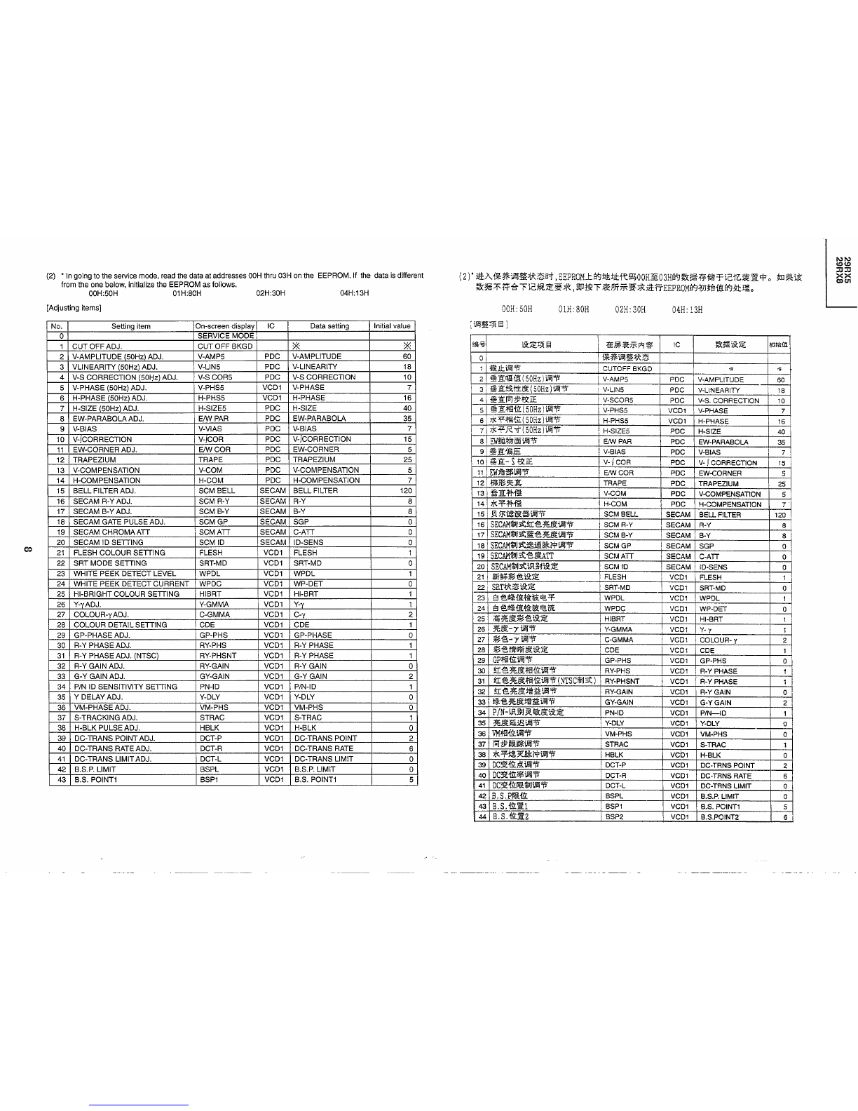
(2) • In going to the service mode, read the data at addresses
OOH
thru 03H on the EEPROM. If the data is different
from the one below, initialize the EEPROM as follows.
00H:50H 01H:80H 02H:30H 04H:13H
[Adjusting items]
No. Selling item On-screen display IC Data setting Initial value
0SERVICE MODE
1CUT OFF ADJ.
CUTOFF
BKGD XX
2V-AMPLITUDE (50Hz) ADJ. V-AMP5 PDC V-AMPLITUDE 60
3VLlNEARITY (50Hz) ADJ. V-L1N5 PDC V-LINEARITY 18
4 V-S CORRECTION (50Hz) ADJ. V-S COR5 PDC V-S CORRECTION 10
5V-PHASE (50Hz) ADJ. V-PHS5 VCD1 V-PHASE 7
6H-PHASE (50Hz) ADJ. H-PHS5 VCD1 H-PHASE 16
7H-SIZE (50Hz) ADJ. H-SIZE5 PDC H-SIZE 40
8EW-PARABOLAADJ. E/W PAR PDC EW-PARABOLA 35
9 V-BIAS V-VIAS PDC V-BIAS 7
10 V-JCORRECTION V-JCOR PDC V-JCORRECTION 15
11 EW-CORNER ADJ.
E/WCOR
PDC EW-CORNER 5
12
TRAPEZIUM
TRAPE PDC TRAPEZIUM 25
13 V-COMPENSATION V-COM PDC V-COMPENSATION 5
14 H-COMPENSATION H-COM PDC H-COMPENSATION 7
15 BELL FILTER ADJ. SCM BELL SECAM BELL FILTER 120
16 SECAM R-Y ADJ. SCM R-Y
SECAM
R-Y 8
17
SECAM
B-Y ADJ. SCM B-Y
SECAM
B-Y 8
18
SECAM
GATE PULSE ADJ.
SCMGP
SECAM SGP 0
19 SECAM
CHROMA
ATT
SCMATT
SECAM C-ATT 0
20 SECAM ID SETTING SCM ID SECAM ID-SENS 0
21 FLESH
COLOUR
SETTING FLESH VCD1 FLESH 1
22 SRT MODE SETTING SRT-MD VCD1 SRT-MD 0
23 WHITE
PEEK
DETECT LEVEL WPDL VCD1
WPDL
1
24 WHITE
PEEK
DETECT CURRENT WPDC VCD1 WP-DET 0
25 HI-BRIGHT
COLOUR
SETTING HIBRT VCD1 HI-BRT 1
26 Y-YADJ. Y-GMMA VCD1 Y-y 1
27
COLOUR-y
ADJ. C-GMMA VCD1 Coy 2
28
COLOUR
DETAIL SETTING CDE VCD1 CDE 1
29 GP-PHASE ADJ. GP-PHS VCD1 GP-PHASE 0
30 R-Y PHASE ADJ. RY-PHS VCD1 R-Y PHASE 1
31 R-Y PHASE ADJ. (NTSC) RY-PHSNT VCD1 R-Y PHASE 1
32 R-Y GAIN ADJ. RY-GAIN VCD1 R-Y GAIN 0
33 G-Y GAIN ADJ. GY-GAIN VCD1
G-YGAIN
2
34 PIN ID SENSITIVITY SETTING PN-ID VCD1 P/N-ID 1
35 Y DELAY ADJ. Y-DLY VCD1 Y-DLY 0
36
VM-PHASE
ADJ. VM-PHS VCD1 VM-PHS 0
37 S-TRACKING ADJ. STRAC VCD1 S-TRAC 1
38 H-BLK PULSE ADJ. HBLK VCD1 H-BLK 0
39 DC-TRANS POINTADJ. DCT-P VCD1 DC-TRANS POINT 2
40 DC-TRANS RATE ADJ. DCT-R VCD1 DC-TRANS RATE 6
41 DC-TRANS LIMIT ADJ. DCT-L VCD1 DC-TRANS LIMIT 0
42 B.S.P. LIMIT BSPL VCD1 B.S.P. LIMIT 0
43 B.S. POINT1 BSP1 VCD1 B.S. POINT1 5
OOH:50H
liJlillllPllil3
}
OlH:
SOH
02H:30H
04H:
13H
NN
<.0<.0
::IIJ::IIJ
XX
COCJ1

1.O
No. Setting item On-screen display IC Data setting Initial value
44 B.S. POINT2 BSP2
VCDl
B.S. POINT2 6
45 B.S.G. BSG
VCDl
B.S.G. 0
46 BLACK LEVEL CORRECTl BLC
VCDl
B.L.C. 1
47 BLACK LEVEL CORRECT2 BLS
VCDl
B.L.S. 0
48 BLACK DETECT LEVEL BDL
VCDl
B.D.L. 1
49 DYN. ABL-POINT DABLP
VCDl
DYN. ABL-POINT 6
50 DYN. ABL-GAIN DABLG VCD1 DYN. ABL-GAIN 4
51 ABL-POINT ABLP
VCDl
ABL-POINT 5
52 ABL-GAIN ABLG
VCDl
ABL-GAIN 6
53 TOF FOCHARACTERISTIC TOF-F VCD1 TOFFO 0
54 TOF Q CHARACTERISTIC TOF-Q VCD1
TOFQ
0
55 SUB-CONTRASTADJ. SUB CON VCD1 SUB-CONTRAST 15
56 BRIGHTNESS SUB ADJ. SUB BRI
VCDl
BRIGHTNESS 140
57 SUB COLOUR ADJ. SUB COL
VCDl
SUB-COLOUR 35
58 TINT SUB ADJ. SUB TIN
VCDl
TINT 55
59 SHARPNESS SUB ADJ. SUB SHP
VCDl
SHARPNESS 63
60 VOLUME SUB ADJ. SUB VOL S-CTRL VOLUME 80
61 TONE FILTER ADJ. S-FIL S-CTRL FILTER 0
62 TXT-CONTRAST ADJ. TXT-CONT VCD1 TXT-CONTRAST 50
63 TXT-BRIGHTNESS ADJ. TXT-BRI VCD1 TXT-BRIGHTNESS 90
64 V-AMPLITUDE (60Hz) ADJ. V-AMP6 PDC V-AMPLITUDE 60
65 V-LINEARITY (60Hz) ADJ. V-L1N6 PDC V-LINEARITY 18
66 V-S CORRECTION (60Hz) ADJ. V-S COR6 PDC V-S CORRECTION 10
67 V-PHASE (60Hz) ADJ. V-PHS6
VCDl
V-PHASE 3
68 H-PHASE 160Hz)ADJ. H-PHS6
VCDl
H-PHASE 20
69 H-SIZE 160Hz' ADJ. H-SIZE6 PDC H-SIZE 39
70 PLL MODE SETTING PLL PLL1/2 TEST 4
71 IGR LEVEL ADJ. IGR-LVL IGR LEVEL 4
72 IGR IGR-ST IGR STEREO 24
73 NICAM ERROR RATE (MAX) N-ERR MAX NICAM ERR-MAX 70
74 NICAM ERROR RATE (MIN)
N-ERRMIN
NICAM ERR-MIN 35
75 NICAM ERROR N-AMDIS NICAM AMDIS 0
76 V-ENHANCEMENT V-ENH DCF VENH 4
77 COLOUR BAND CBPF DCF CBPF 0
78 1 LINE DOT IMPROVEMENT LD DCF LD 0
79 CORING CORING DCF COR 0
80 PIP H-DISPLAY POSITION H-POS PIP POS-H2,POS-H 16
81 PIP V-DISPLAY POSITION V-POS PIP POS-V 16
82 PIP SUB TINT PIP-TINT VCD2 TINT 35
83 PIP V-POSITION VSIDLY5 PIP VSIDEL 10
84 PIP H-POSITION 150Hz) HSIDLY5 PIP VSIDEL 3
85 PIP H-POSITION (60Hz) HSIDLY6 PIP VSIDEL 2
86 PIP DISPLAY ADJ. VSPDLY PIP VSPDEL 0
87 PIP SELADJ. SELDLY PIP SELDEL 2
88 PIP Y-DELAY (PAL) YDLYP PIP YDEL 0
89 PIP Y-DELAY (NTSC) YDLYN PIP YDEL 0
t!ii-li}
i5l:;E:~
§
:t£)jf.*:~p'q~
IC
l:t:lJiH5l:;E:
mr.>1Jt
45 B.S.G. BSG VCD1 B.S.G. 0
46
~'@.f'\!:!jZf.lCiEl
BLC VCD1 B.L.C. 1
47
~
'@.E@.:!jZf.lCiE2
BLS VCD1 B.L.S. 0
48
~'@.~~f'\!:!jZ
SDL VCD1 B.D.L. 1
49
DYN.ABLfiLIt
DABLP VCD1 DYN. ABL-POINT 6
50
DYN.ABL:m~
DABLG VCD1 DYN. ABL-GAIN 4
51
ABLfiLll:
ABLP VCD1 ABL-POINT 5
52
ABL:m~
ABLG VCD1 ABL-GAIN 6
53
TOF
F04'iftt TOF-F VCD1
TOFFO
0
54
TOF
Q4'iftt TOF-Q VCD1
TOFQ
0
55
~m
l:t.§£iJilJTi
SUB CON VCD1 SUB-CONTRAST 15
56
~j~.§£iJilJTi
SUB SRI VCD1 BRIGHTNESS 140
57
~j~'@.iJilJTi
SUB
COL
VCD1 SUS-GOLOUR 35
58
~J'@.iJilJiJi!lTi
SUBTIN
VCD1
TINT
55
59
~J~~'§£iJilJTi
SUBSHP
VCD1 SHARPNESS 63
60
~j
if-:l:iJilJTi
SUB VOL S-GTRL VOLUME 80
61
if-iJilJill
ilU~
iJ/ilTi
S-FIL S-GTRL FILTER 0
62
TXTJt-t
l:t,iJ!:iJiilTi
TXT-CONT VCD1 TXT-CONTRAST 50
63
TXT3!E,iJ!:iJilJ
1'i TXT-BRI
VCOl
TXT-BRIGHTNESS 90
64
~1l:.$iHI(
60Hz
)iJ/ilTi
V-AMP6 PDC V-AMPLITUDE 60
65
~
1Hlttil£
(60Hz)
iJiilTi
V-L1N6 PDC V-LINEARITY 18
66
3E1l:./il'ltFf.lCiE
(60Hz
)iJi!lTi
V-SCOR6 PDC
V-So
CORRECTION 10
67
~1l:.:j:§fiL
(60Hz)
iJi!l1'i
V-PHS6 VC01 V-PHASE 3
68
7J<
:!jZffifiL
(60Hz)
iJiil1'i
H-PHS6
VC01
H-PHASE 20
69
7J<~
R
't
(60Hz
)iJiilTi
H-SIZE6 PDC ' H-SIZE 39
70
PLL:l*~i5l:;E:
PLL
PLl1/2
TEST
4
71
IGRf'\!
:!jZiJilJ1'i
IGR-LVL IGR LEVEL 4
72 IGR IGR-ST IGR STEREO 24
73
NICAM1liIj:a:~~$
(l'it;lc) N-ERR MAX NICAM ERR-MAX 70
74
NICAM1liIJ:a:~~$
(ii/j,
)N-ERR MIN NICAM ERR-MIN 35
75
NICAM1liIj:a:~~
N-AMOIS NICAM I AMDIS 0
76
~1l:.m~s
V-ENH OCF VENH 4
n
~'@.~li!i
CBPF
OCF CBPF 0
78
li1.};'H~fr
LD OCF LD 0
79
~it
CORING OCF COR 0
80
PIP*:!jZ~lJ'fiL:R
H-POS PIP POS-H2, POS-H 16
81
PIP~1l:.~lJ'1i'Lii
V-POS PIP POS-V 16
82
PIP~J'@.j}Iij
PIP-TINT VCD2 TINT 35
83
PIP~llfiLii
VSIDLY5 PIP VSIDEL 10
84
PIP*~fiLii
(50Hz)
HSIDLY5 PIP HSIDEL 3
85
PIP*~1i'Lii
(60Hz)
HSIDLY6 PIP HSIDEL 2
86
PIP~lJ'j}lijTi
VSPDLY PIP VSPDEL 0
87
PIP~~iJiil1'i
SELDLY PIP SELDEL 2
88
PIP1Eil£ji£j8
(PAL1liIJ:a:)
YDLYP PIP YDEL 0
89 PI
p~~ji£j8
(XTSC1lilJ:a:
:YDLYN PIP YDEL 0
"'"
<Dec
:xJ::I
~~

.....
o
No. Setting item On-screen display IC Data setting Initial value
90 PIP PLL SETTING PLLTC PIP PLLTC 3
91 PIP FRAME LUMINANCE YFC PIP FRY 10
92 PIP FRAME COLOUR UFC PIP FRV.FRU 0
93 PIP FRAME WIDTH FRM PIP RWIDV,FRWIDH 12
94 OSD "MICON HR 9
95 STANDARD SOUND SYSTEM S-SYS MICON BG
96 LANGUAGE OPTION SETTING LANG MICON 255
97 PAL-TINT SETTING PAL-TINT VCD1 TINT 64
"For 60 Hz data, enter the following values in the data set for 50 Hz.
Setting Item Offset Value
V-AMPLITUDE ADJ. 0
V-LINEARITY ADJ. 0
V-So
CORRECTION 0
V-BIAS -4
H-PHASE ADJ. +4
H-SIZEADJ. -1
III INITIAL CHANNEL SELECTION DATA SETTINGS
1) Call up the service mode. Enter MCL1 to make the settings of the channel selection data on the
EEPROM (see the next page). Then select the channel POS1.
Factory
settings
and
geomagnetic
adjustment
model by model
(reference)
Suffix for model number Geomagnetism (H,V) nT Background Language S-sys
B30000 20000 12300K CHINESE I
C(SINGAPOLE) -10000 40000 12300K ENGLISH BIG
iil%
i5l:~JjQ
13
t£~:&:~pq~
IC
;k~i5I:~
joJJltilfiI
90 PIP
PLLi5I:~
PLLTC PIP PLLTC 3
91
PIP~31EEl
YFC PIP FRY 10
92
PIP~~~
UFC PIP FRV, FRU 0
-
93
PIP~~El
FRM PIP FRWIDV. FRWIDH 12
94
t£m~1l"
"MICON HR 9
95
~/'I£1I'IIJOJ~UJt
S-SYS MICON BG
96
ii%§~l$i5l:~
LANG MICON 255
97
PAL*,Ji\:~iJliJi5l:~
PAL-TINT VCD1 TINT 64
*1
50Hz~jJ5i.5I:~st,
~,~]iiJliJ11=lti5l:~~jJ5ilif;iltIT60Hz~jJ5S'9i5l:~0
i51:~~13
i
-t!ii~{i
~
1i:
$lil
m:
jjJ11 I0
~1i:~f.EEliJliJ11
i0
~1i:IiiJ%~IE
I0
~1i:-t!iiff
!
-4
7.K~~ttillil11
+4
7.K~R>tiJliJ11
I
-1
III
~
~
r£ml¥919J~~mj5t:iE
1
)IJlf04f:liH·FjjJ~tI:~1H~"'F~FJT~~*,EF.jMCL1*:I4~.g.fJ(mi.5I::JE:TEEPROMZ.9='
(.!:i!.
"'F9i')0
fA.
ITS,
~l$POSlo
*
~
%
t:e
r:
a-g-l3'9
*J.J'!l'€!i~5FO
~j:mlft!ij
~
(
~
~
)
~-"}~~
liilJ:iJ(*~,
~1i:)nT
'If,*
'0;:-
s-svs
'J;c i=i
B30000 20000 12300K
9='Jt
I
C
(~.1JIlf&:)
-10000 40000 12300K
~Jt
BIG
NN
<0<0
:0:0
XX
cocn

...
...
FACTRY SETTINGS
1) Using the keys, make the following factory settings on the EEPROM
ITEM DATA SETTING
SKIP OFF
AFT ON
C-SYSTEM AUTO
S-SYSTEM '1
IGR FORCED FM ON (29RX5 ONLY)
IGR MODE ST, MAIN (29RX5 ONLY)
NICAM FORCED FM ON
NICAM MODE M1
LAST POWER ON
LASTTV/AV (MAIN/SUB) TV
DIGIT 2DIG
LANGUAGE '1
BULE BACK ON
AVMENU
STANDARD
AUTO SELECT OFF
LAST POS (MAIN/SUB) 1
LASTFB
POS 1
VOLUME 0
BALANCE 0
CONTRAST INITIALVALUE OF EACH AV MENU MODE
COLOUR INITIAL VALUE OF EACH AV MENU MODE
BRIGHTNESS INITIAL VALUE OF EACH AV MENU MODE
TINT INITIAL VALUE OF EACH AV MENU MODE
SHARPNESS INITIALVALUE OF EACH AV MENU MODE
YNR INITIALVALUE OF EACH AV MENU MODE
BKGD INITIAL VALUE OF EACH AV MENU MODE
TREBLE INITIAL VALUE OF EACH AV MENU MODE
BASS INITIALVALUE OF EACH AV MENU MODE
U-BASS INITIAL VALUE OF EACH AV MENU MODE
SPATIALIZER INITIAL VALUE OF EACH AV MENU MODE
TIMER CLEAR
SAVE OFF
HEAD PHONE AUTO ILEVEL: CENTER)
INSET TINT 0
DEMO OFF
PIP DISPLAY POSITION LOWER RIGHT
'1:
Refer to the Job Instruction Sheet.
For S-SYSTEM, the following factory settings 1, 2, 3 and 4 can cover all the channels.
1: M 2: B/G
3:1
4: D/K
t:e
rr
a-r
1¥9
*J]3!~~
i..~
JCE:
1
)*-r
~?JTjf-~*ftt*!ii;lt:fl3@:B<J~UB.,
J<).
i!~~M~iilj':i!::iETEEPROMZ
e:p
0
i,5l::iEr.9!
gj
~!i5i&::iE
mVi:i,5l::iE
fiLji
~
AFT 3f
~~i!iIJ:<ti,5l::iEfiLji
§Z9J
p;=a'i!iIJ:<ti,5l::iEfiLji
'1
!GRs!
i!iIJ~~i,5l::iE
fiLjI
3f{~~29RX5)
IGRi!iIJ:<ti,5l::iE
fiL:ii
STEREO(:iLf*Jl'f)
.±~~
"MAIN"
(~~29RX5)
NI
CAMSSi.i!iIJ~~i,5l::iE
fiLjI
3f
NI
CAMi!iIJ
:<ti,5l::iE
fiLii
Ml
II:S
El!
lJ~GF
~
i,5l::iE
fiL:ii
3f
II:sEl!'!:\iI./;a~i,9::iEfiLji
(.3:./11J
El!'!:\iI.
~~i,9::iEfiLji
-fiL~
i,:g:~i,5l::iEfiLJI
'1
ili
~
'If*i,9::iE
fiLJI
3f
p;~j2'£:iEfiLii
fif-/t
§Z9Jj2'£:tffiLii
~
l'isi,5l::iEfiLii
(.3:./iilJ)
1
II:s
FBi,5l::iE
fiLii 1
'/if:l:
i,5l::iE
fiLJI
0
titi
"fWi,5l::iE
fiLii 0
~
~t
13'U5l::iE
fiL
Ii
~P~j2'£:tfr.9!gjB<JM~m.
*~~i,5l::iEfiLii
~P~j2'£:tfr.9!gjB<JM~iil
j!EJ3{
i,5l::iE
fiLii
~i5"~j2'£:tfr.9!
gj
B<JM~Sm.
-B
~j.5l::iE
fiLii ~
Jl'f~JiE:tfr.9!
§I
B<JM~~m.
~
IJI3
J3{
i,5l::iE
fiLii'.
~Jl'f~JiE:tfr.9!
gj
B<J1<msm.
YNR
~P;~JiE:tfr.9!gjB<JM~m.
BKGD
~P~JiE:tfr.9!
gj
B<JM~Sm.
j@j
'/if
i,5l::iE
fiL
ji
~P~JiE:tfr.9!
gj
B<J1<.msm.
1~
=a'
i,5l::iE
fiLii
~P;~JiE:tfr.9!
gj
B<J1<.m~m.
~
1I£iH5l::iE
fiLji
~P;~JiE:tfr.9!
gj
B<JM~~m.
SPATIALIZER
~;a~JiE:tfIJii
gj
B<J1<msm.
:iE1It
*
j.5l::iE:
fiL
ii
!J3~
~!i51*:
fH5l::iE
fiLii
~
~ilPHJl.i.5l::iE:fiLIi
§Z9J(El!"f:
e:p~)
IIJ
~Jjf.
'@.
~j.5l::iE
fiL:ii
0
7J'
~
i,5l::iE
fiLlf
~
PIP,'i7J' Jjf.
i,5l::iE
fiL
Ji
ti-r
'1
:
~~p;ifi!ilJ:<tB<Ji,5l::iE,
~tIJrIltB<JM~Siilj]L
2, 3&411t,
iiJi,5l::iE:?JT~~J1to
l:M
2:B/G
3:I
4:D/K
1\)1\)
(.ClCO
7.17.1
XX
COUl

SERVICE ADJUSTMENT
PIF/AFT/AGC ADJUSTMENT
f*~iffiJ~
PIF
/
AFT/
AGCI¥.J
iJj!!ij~
1\)1\)
<0<0
:Il:Il
XX
COC1J
10kO
- 1.5dB±0.8dB
100kO
~I&U
-c
001
E-9~iIil:
002
750
s1000p
"'~~l!l~
1000p
o-I~
2.
ttJ~t'iH~~VCOI3
J%i:~~~
:T203
(Tl03)
1..
Mjcttl~~~w:
tl:l7C~0
2.
X'tIC20l
(IClOl
)~"I$lI
(4) (IF
ACC
)Jil[tJll1l:i:JiE~EEo
6.0+0.lV
TP202(TPI02)
3.
jlH5i:iil;;;\;~EEitl9!tl;!li:IC201
(ICIOI)"I
$lI
(20)
(PLL
FIL)
~1f.i:JiE~EEiilo
TP203(TPI03):~0.007V~~~IOkHz
*&H~~Jili'iJ~:lrlVH~.ra31!L~~~iil;;;\;~EErr
0
4.~~i!tJll~IC20l(IClOl)"I$lI(4)~1l:i:JiE~EEo
5.
fi§A.7C~.
~1&E-12!Ji!jBI!1i3%
0
(AFT9t~*f;lJ:I1t~at
,1i4~1&!Ji!jf~lt!j~:i'E~224.
25MHz)
6.
~~1t;;;\;~EEit~IC20l
(IClOl
)~"I$lI(20)o
~'PT203
(Tl03).
~~EEiilJ2s~~3
.I.iiiPJTl9!~:!ittl:l~~iilo
$ilfm:15iI
:+0
.015V(20kHz)
1.
~i~~IFT(~i~)~~~:TU20l(TUlOl)
1.
T7'Gfil/%\'iiAi¥.Jl'll:i&:f*;;i5"F.
1l!~l\UBH
l'll:i&E-9~l1itli!!%z:t!t;;!;i.
~'PPLLf&!!:L
2.l'll:f.3m~llifl\'ii
l!l~I!l!lT~lWfl5'i:~l'll:~~
(M~f.3m).
3.
~r,HI!)iHU~~
l!l
!\!ljl-j980d81l
v.
4.l'll:IlfiJJ2l'1I!!.lt('I!l';g~!lJi:fli¥.J1ll;~JHJtj~Ht;
.!A!.
001)T~lWfl"'~\'iil!l~.
(Rfi'€!iiHtT~
l\'!ifl"'~~l!l~).
5.
RM~
El
~~~!!i!tlJRF
AGCi¥.J
!\!.ffi:il!ITO:3?:
6V~
i¥.J
.!;IJlt%::r:l'll:Mzfl'LIL
6.
N~~l'li'fl"'~!!.ltI!l!lJ9T~!lJi:%~3[002J9T~
i¥.JJjIlI,laJ!*.
~~:~~~~~~.
~~~L~Mfl~~W
1iJ:fi
•
-1.5dB:l: O.8dB
10kn
100kn
Oscilloscope
Fig. 1.
E9CH
1000p
o---I~
Fig. 2.
1. Disconnect the antenna from the tuner antenna terminal.
2. Apply DC voltage at pin (4) (IF ACC) of IC201 (IC101).
6.0 +0.1 V TP202 (TP102)
3. Using a digital voltmeter, measure the DC voltage at pin (20) (PLL FIL) of IC201 (IC101).
TP203 (TP103):About 0.007 V corresponds to
10kHz
.
• Prepare a digital voltmeter capable of reading down to the third decimal place.
4. Remove the DC voltage from pin (4) of IC201 (IV101).
5. Reconnect the antenna and receive the E-12CH signal. (With the AFT off, set the receiving frequency to
224.25 MHz.)
6. Connect the DC digital voltmeter to pin (20) if IC201 (IC101). Adjust T203 ( T103) to get the voltage
measured in the above step @.
Allowable error: +0.015 V (20 kHz)
2. vco ADJUSTMENT: T203 (T103)
1. Get the tuner ready to receive the E-9CH signal,but
with no signal input. Adjust PLL data.
2. Connect the sweep generator's output cable to the
tuner antenna. (RF sweep)
3.
Adjust
the
sweep
generator's
output
level to
80dBIlV.
4. Connect 1heresponce lead (use a low-impedance
probe with wave detector; see Fig.t.) to the tuner's
IF output terminal.
(This terminal must have the probe alone con-
nected.)
5. Set the RF AGC voltage to 0-6V with no contact
with waveform.
6. Adjust the tuner IF coil to obtain the waveform as
shown in Fig.2.
Note: Be sure to keep the tuner cover in position during
this adjustment.
1. TUNER 1FT(preset) ADJUSTMENT: TU201(TU101)
IF-oUT
...
I\)

PIF/AFT/AGC ADJUSTMENT
PIF/AFT/AGC~
i./i!IlI_
3. AFT ADJUSTMENT: TP204(T104}
1. Receive the E-12CH (PAL colour bar) signal. if this
signal is not available, any signal above the E-5CH
band is acceptable.
-Field strength:
55-80
dB~N
Make
sure the
frequency
is
almost
the
same
as
that of the received channel (± 3011Hz).
2. Using the channel setting control, make a frequency
of 224.25 MHz
appear
on the screen. (AFT
011)(11
any other channel than E-12CH is received, make
its frequency on the screen.)
3. Turn
T204
(T104) coil clockwise first to have 6V
reading and then
counterclockwise
to get 0.2 V
reading.
Within this range, adjust this coil to reach the volt-
age below.
4. Adjust
T204
(T104) so that the DC voltage at the
AFT
OUTterminal
- pin (1) of IC201 (IC101) be 3.3
±0.1 V. (See Fig. 3.)
DC
voltage
at TP201
6V
3.3V
DOWN A S' S Ill" C UP
Fig. 3.
• Turn the core counterclockwise for the UP di-
rection, and clockwise for the DOWN direc-
tion. Adjust the T204 core to point B (between
B' and B"). Point A and C are rejectable.
3.l3iYJt'i.tiJiiJAFTB-'JiJiiJJM:T204(T104)
1.1ti/l(E-12~iJ:t(PALttJ:itlGi~){s-l9'.
7GE-12
~.m4.Al!t.
~Jll~5~.~~~
••
{s-'%1't'l:l'.
itl;iUj1illt:
55-80dB~V
Milj.iEW!J:iI!!iJlijl'ilii/l(~iJ:ti¥J.$(
±
30kHz).
2.iilii±!IJ!iJ:tNlE**.
iJlijj)t3H~7i't±li¥J!IJ!$
~
-m:
~
224.
25MHz.
(AFT
~
'1"
*
~
tt
~).
(lti/l(
~
7E-12~
Jlt
~
~~
i¥J!Wl
iJ:t
fa%l!t.
!IZ.
~*Jjj
Eq;ii;;m$:i¥J.$).
3
.I;!.Jif!l(atH)]rli:JME~T204(T104
)~gj3atB-'J1'JJMi
Jtl..EEj;6V,
i9!atHjJrli:JME~atB-'JWMiJtl..EEj;
o. 2vj;iltrm,
iJiiJi'JT204~gj3
,~~gj3
<=P
~tLji
B-'JJtl..EEmJ<S~""f~[',~*o
4.iJiiJi'JT204(T104),~IC201(IC10l)51~(1)
(AFT~t!:l!ljjij
)B-'JH.l:IiEJtl..EE-mJ<S~3.
3V±O.1
Va<J
m.JE~*o
TP201Ji"JJ[tm.rtffi
6V
3.3V
H$
A B' B
B"
C
n$
003
*
litH,'
j;~8tH:1ji!;J8t~
~f$,
:Ef
1J11~
8tH:1jfi;J8t!ilIJ~H$o
l£B'
EqB
H
.<:.
is]
Mm~~T204i¥J1itt'L,{j'[illmJmT
BA.o
(A,
CA1JNG)
5. VIDEO DETECTION LEVEL ADJUSTMENT: R224
1. Receive the "B/G SYSTEM PAL COLOUR BAR" signal (100% white colour bar). Ste the S system to B/G.
2. Adjust R224 so that the video output at the AV OUT terminal be 1.0 ±0.05 Vp-p with a 75-ohm termination.
4. RF AGC CUT-IN ADJUSTMENT: R226 (R116)
P201
(P101)
rtt!ll.ti1.
004
+JI 0
+
-wlBin
7i'1l!i:U
t..9..
1
Y
4.
M~13
iYJ:tt\'~~*1JRF
AGC1lIlAB-'JiJiiJ~
:R22B(R116)
1.~41l:E-12~j1[
"PAL*U~*3~"
1~%o
itl;iUj1illlt:
57±
IdB~
V(~1t75'PIHIl.)
2.
l1H!l4fj1f
7i'
j!:,jt
It
7i'
lI!i:
H
'1"
P201.
it
-wlBifl
:
~6.
5V
3.
ME~R226
(R116),
~FJrl!.Qtl<i!.EEil~:j(J3~Jll*o
4.
;f§&jJrli:Jm:f§!j:i!?ME~R226
(R116)
,.j4<i!.EEil
;tiJiiJ~Jll*m-o
.1VZ~j,J3!:o
5.
iJlij1El-'%51illlt~63-67dB
~
V.
W!Jl.\.7G~j'll'
t±l
m.
6.
NiJIij{"a--,%j1illlt~90-95dB
~
v.
W!Jl.\.7G~llt
fill-l9'iJlijttJitHst±lm.
i'E1i :
:llcjiIHI1!Jll::r-*50/75~!l.tltfH~fli¥J500
~~l;iU51illlttt.
~J;ib51illlt!f<:·~~~55
±
IdB
~
V.
~~~.
iI1!Jll~~fll!t.
B:;lfJ:!R
E!3
~~fl'fjH~i¥J~.Il.!Jtm;1<;.
5.1'Ji!.~~~Jtl.~B-'JiJiiJ~:R224
l.lii/l(
"B/Gfi1IJ:itPAL~~"
{i1!%(lOO%s'@.fl1f%).
tll:S-fillJ:it'fB/G{12I.
2.
iJIij
l'iR224.
iI1!j'll'
~
~
t±llt/HI:
i¥J
t!lI.!IJ!~
t±lj1illltii;J£l.
0±
O.
05Vp-pi¥J
mlE
j!:,jt
('1"750
Ii
~~).
i'E1i:
Jll
"IfillJ:itPALlGi~"
1EI%*i£ffJltJ3lliJlijJMl!t.
B:tll:StlJ:it'fI{;LI.
P201
TV
set
Fig. 4.
Oscilloscope
~
1. Receive the.E-12CH "PAL COLOUR BAR" signal.
- Fieid strength: 57 ±1
dB~V
(75 ohms open)
2.
Connect
the
oscilloscope
to P201, as
shown
in
Fig. 4.
- Bias box: About 6.5V
3. Turn R226 (R116) to have the highest voltage.
4. Turn R226 (R116) slowly in the oppsite direction
untill the voltage goes down 0.1V below the high-
est level.
5. Adjust the signal level to 63-67
dB~V
and make sure
there are no noise.
6. Now adjust the signal level to 90-95
dB~V
and make
sure there is no chrominance modulation beat.
Note: If a 50 ohm field strength meter is used without a
50/75 impedance converter, set the field strength
to 55 ±1
dB~V.
Pay attention to a loss that would
be cause with the converter.
....
W
NN
(Q(Q
JJJJ
~~

....
J:>,
DIGITALCOMB FILTERY LEVELADJUSTMENy
1. DIGITAL COMB FILTER Y LEVELADJUSTMENT: R5467
1. Input the PAL colour bar (100% white colour bar) signal to AV-IN terminal with a 75 ohm termination
(input level 1.0
Vp-p
+0.05Vp-p).
2. Connect the oscilloscope to
TP5462
(connector YA pin (7)).
3. Adjust R5467 so
that
the Y signal (100% white) at TP5462 be 2.0 ±
O.lVp-p.
Note:
Make
sure
that
the
signal
is
linearly
amplified
overall.
(The
100"10
portion
should
be
kept
intact.]
<Reference> Note the voltage level for the adjustment with the E-12CH signal.
To be adjusted to 2.0 Vp-p at TP5462
• Make sure the above value is available after the adjustment
No.5.
Input (YB) (2): 2.0 V +0.1 Vp-p
Output (YA)(7): 2.0 V +0.1 Vp-p
SOUND
ADJUSTMENT
1. SUB SOUND ADJUSTMENT (BUS ADJUSTMENT)
1. Feedthe following signal to the AVterminal.Signal: 1 kHz, 1.76Vp-p (terminated with a 10-kohm impedance),
0.04/-0.06 Vp-p
2. Set the volume control to MAX.
3. Connect the VTVM probe to the
Sl
connector. (Pin G): L-ch, pin ®:GND, pin @: R-ch)
4. Adjust the sub-sound data so that the VTVM should read the following voltage. For the left channel.
Adjustment error: B.9+0.1 Vrms
Notes:
• Spatializer off
• In the S-Normal mode
• S-VOL control at MAX position
'Use an B-ohm dummy load.
2. NOISE MUTE CHECKING
1. Receive E-12CH "PALcolour bar" signal.
2. Turn up the volume control to maximum and make sure the sound is heard from the speakers.Then put the
unit in the no-signal state.
3. Be sure that the sound mute is effective.
4. Finally turn down the volume control minimum.
._*~m~_~~~~~%~~~~~
1.
~:~r't~t[%l'.tliUg,~J3£1~%~1JZ~ifol~:
R5467
1.3mt1:75
Q~~[Q]AV$tA~$tAPAL1IiJj~~-@.
(100%S
-@.
)1~%o
(~A~1JZ111.
OVp-ptO.
05Vp-p)
2.~~ht~TTP5462(11fi~~YAl71Df;ll(7)
)
3.
ifoll'iR5467
,ftTP5462.J<t~~J3£1~%(
100%S
-@.)
~1JZJ2s¥:2.
0±0.1
Vp-p~%W.i'E~*o
tt~
:~it~1:ljd:\l£1J:~tttiS':*o
(100%S-@'1~%:giHH:\l11.:iE1jt)
<~;lf)
fflE-121Wfi!!1~%t:@:1i\tifol~ffl~~
1JZo
Jltat ,
~1i\tTP5462.J<t~~1JZ~~
112.
OVp-po
•
~5Iji'[ifol~~*J§
,~it_HIJPJT~~~m.~~~1S%W.i'E~*o
$tA~1JZ(YB)
(2): 2.
OVtO
.1Vp-p
$tA~1JZ
(YA)
(7): 2.
OVtO
.1Vp-p
II
"y:!IE1"'i9f
fijlJ
::a: i¥.J
iTo'iI
:m:
1.
iUpoi'1r(I(Jj)lijM(~~B'!*,J)
1.
[Q]AmA~$tAi<J.
""f1~%o
1~%!iX:?t:
1kHz
,1.
76Vp-p(~~10kQ
~~ll.)
,0.04/-0.
06Vp-p
2.i.5t'lif:!i1S!lliHiii*1lLJi
3.
~VTVM(
~T'if~EEi.t
)~~HTSI11fi~~o
(l7IJJtjJQ):
:tt:?5i1!,
l7IDf;l1@:
~±ik~,
l7IJJtjJ@:{:;?5
iI!)
4.
ifoll'ililljPi'lif~~,
ftVTVMpJfl!i!~~~J2s¥:""fJljPJf~~J5!iI.i'E~ffm.o
(1£:tt:Piil!at)
ifol~~~:B.9tO.1Vrms
tt~:
•
il'1l:l'r.-l*,a'B'!ll1tl
:
OFF{i'LJt
•
;r,l'lPO
i'1rttt
~{i'LJt
.i'1r1l :m:*{i'LJ!:
*ftfflB
Q
a'<Jffi(
jQ~o
2.1/!ji'1r=9'J1Ill(I(J~:l!E
U~l/1l:E-12Jjjj(iI!
"PAUljit*3,*"
1~%o
2.
~i'1r:l;B'!ll1tlTm:*{i'LJt.
It.~fl:thPOjU}(l(JPOi'1rml±l.
1'/.),6. iIl:i%mtrLT7G{i1I%ltt&ttt
~.
3.
J1t1lt.
~3ll:il!l
i'1r=9'JIIll~1':'l'ijI]f1:.
4.>Ill,6.
~i'1rIl:~*,JTm:/J,{i'LJt.
1\)1\)
<Dec
::ll::l:l
~~

AoB
mA
aI
_-+_
b
CRT-l'ilJ!1
"A"
*7il
CRTtdll'[
''A'' *
~m
lI'J'il
, £.
itJ!:s:ilt'ff**if..lJM;jj\:~,!'iC"f!'f<~
~lf'YlrjJ01L,
~mf!j'[E!P~
11
t(!'@.:£
Stt))f.i1L1',o
0'llljlllli!l.icl1C"f
"R"
(t.[:,
"G"
(~)~
"Cy"
(~)~,~mf!JIIDiI.ic
~11::±:l.j:§G.~t(l.~i:~mlIT!.~,
•1•
~~~~i!Lli
(I'PB~tt
"a"
~
"b"
:!frm.~iJIjJ~):
[CRT~JiI!,:
VB68LEP'
"•
==>
20
~
rn.~
,
CRT~JiI!,:
VB68QBC'"
==>0
u
rn.~
j
~t.[~i:~m
~lii~i:~m
~~~.l:3£~iJi"ij~
2 _
~me*3~J.3£.SkJiftij~
1.
!iffliA~~~[JJ
(YPB
)tLll.iE!ifflo
f~t&m4tOO;$;f§-,}[email protected]'e~~[JJUif..lYH~YVo
:
1£30
f'YP"lm~**~;E~~~~[JJo
)
2.
i5l:li~~~i:'!f(mlIT!.7i':,
1fi5l:it~
i"*~Vif.11
14001
11:10
3,
tEBH110
.BV11f'=£~*~~;Ef1[;;;'11f"f,
5ffJiA.itl.:€B~ffm.'iL~i5'i5~IjAt&~*o
31o~ff
~*,
mM1~Jtm&-A:.<...tmif..lA:Ym.~0
~tmif..l~i~~I:l!lf'=&'c~'U~~ep)iJT~o
, I,
mj£tN%i5l:!'E~t!\\fJ1.11i:~~~m~~,:i!f
j@i1mr.$:t~~ljif..l~T*~Vif.111,
4mAo
2.
j@i11i1l~~[JJmJH&lIT!.fJl'l1fCRTf'F1Gi:Ii!l~
iltfl
o
It:
~±mif..l~i'iJ~~f'&'c~U~~itt1T,
~m~±m
tIWil1ri5l:;Eo
3,
if..I~~~~~~jj;ljiilt~,
{ilA:~±mli!Yf
110,
~
••
ittffmif..lo
~€,~~tt~~~~~~
li!~{il~
ep
J<t
*=
i5.?tA!Jl:
fl-;;;}(
0
4.
~i;i]~~~[JJ,
m$:*'il'fi!.w.~
"a"
fO
"o"
i!L
]'U!:a:t!oI!lAJiJr~.
i5l::!frm.~j]20,urn,
:i!f-MiA.
~~~~**,~~~~[JJ~~~~~rn~
'¥j§ijo
4,'
t!o
"a"
~
"b"
i!Li[,¥j§ij~*=~fi,t.&7i:i~
epxt*~!Jl:¥AB!Jl:o
5'
if..I:J'CIt~1<il
11
lE.*OJ3to
6
,.Iiii~~~~[JJ~~~~~,
~~JJj;§:
108±
20N(
11+2kgf)0
7,
T:Ut~Jjf&lIT!.f~'I1f~m:J!ri-$o
t!o~:i6'fl-,
miilt
Jt'!3{lE.:!frm.~,
~'<'i5~IJA!Jl:\<J-..t~~/.'E~*o
It;
ittffJ1tJjjfif..l§'lf?:'<'
fi1f,
J5I5tffl1400+50
u
A~-+
*~Vif.Bi~~Jjf&lIT!.fi.12'30:5j-!~rjJ\<J-
Lo
t!otE
ffi~M~~7A:~Jjjf~~iJ)jj§'lf?:,D~tEif..I.
ti?~~~.<.
iitr,
:i6,{ro::i!f-ittff2:5HrjJ\<J-..t~%!~o
It:
~ttTPIOOI
(TPI002)
\<J-&~~Mi..t~~~
~,
il'!f(mlIT!.~::±:li:~~o
It.
if..I§'If?:~
••
g{J§
,~iJiji5l:
"an
~
"b"
fim
.~1120\.l
rno
A=B
Fig. A
,
I
aI b
+:--~-
"-I-
i
I
!
Rank "A" (on the Rank "A" (on the
right of theCRT) left of the CRT)
" Holddownthe single- colorkey for 1secondsor longer,
whether in the service mode or not, and the single -
colour modeis called up.Alsowiththetext keys"R", "G"
,and "Cy", the
corresponding
single-colorscreencomes
up.
"1: The deflectionyoke position(YPB.is adjusted by set-
ting the "a" and"b" landings.
[CRT code: VB68LFP""" ==>20-!lm point,
CRT code: VB68QBC"""==> o-um point]
RED ONLY
SCREEN
BULEONLY
SCREEN
SINGLE-COLOUR
I~
,
MODECLEARED
GREENONLY
SCREEN
PURITY ADJUSTMENT
1. Using the remote controlier, cali the green-only
screen.Setthe contrast control to have a beam cur-
rentof 1.4
mAo
2. Fullydegaussthe cathoderay tubewith the degauss-
ing coil.
Note:The magneticfield adjustment is referred to in the
Production Communication Sheet. See the factory set-
tingstable for the magneticfield.
3. Setthe purity magnetto the zero magneticfield, and
roughlyadjustthe convergence.Now adjust the pu-
rity magnetto get the centering rank A.
4. Movethe
deflection
yoketoandfro,and
observe
the
points
"a"and"b"as
shown
inFig.
1-1
witha
microscope.
Setthe
landings
to20urn.Insertanddrivethe
wedge
tokeepthe
deflection
yokewell
balanced
topand
bottom.
4'. Ifthepoints"a"and"b"arepoorly
balanced,
correctthe
centering
uptotherankAB.
5.
Adjust
the
raster
rotation
to0
eastward.
6.
TIghten
the
deflection
coillock
screwsTIghtening
torque:
108+20N
(11
+2k9n
7. Checkthe
corners
onthe
cathode
raytube
screen.
Cor-
rectthe
landings,
as
required,
totherankAby
applying
the
magnetic
sheet.
Note: Makethis adjustment after warming up the unit at
thebeamcurrentof 1400+50!lA for30 minutesor longer.
If any other adjustment is made during the warming-up,
warm up the unit for 2 more minutesand start the purity
adjustment.
Note: Call the service mode with TP1001 (TP1002) and
pressthe single-colorkey on the processremotecontrol-
ler,and the green-colorscreen comes up.
Note: Afteradjustingthe convergence, set the "a"and "b"
landingsto 20 urn in advance.
2" SURROUNDING PURITY ADJUSTMENT
1. Make sure the deflection yoke (YPB) is positioned well. Receive the crosshatch signal and move the
deflectionyoke to roughly adjustthe YH and YV.(Fix the deflectionyoke with the wedge within 30 seconds.)
2. Call up the green-only screen,and set the beam current to 1400!lA.
3. With BH at 0 and BV as specified by the Production CommunicationSheet, make sure the landings at the
cornersare of rankA. If not, apply a purity correction magnetand readjustthe landings.
The magneticfield adjustment is referredto in the ProductionCommunicationSheet.
....
CJ1
I\:lN
(QUi
:o::x:
x><
CX)(J1

CONVERGENCE
ADJUSTMENT
.imim~~~s-g1.n'iJ~
1\)1\)
<0<0
::0::0
XX
COOl
~J(~~~~~
1.
~"F
ld;J!*~"P~m)iij
ii:l
~
J(~ll!:.
a) OOa: !lllilldNm=r
"a"
•
ltlJ:.miYJ{li;~HlI.
1l!!l.1mW-~"P
•
b)
OOb:
!lll~~mT
"b"
~
"c"
,!oHm
~iliofil1lt
1lfIl.1mW-
~"P.
c)
!lc:
~Iill~~m
"c"
•
Itl:t;m~iliofi~
ll!!l;fmW-illd"P
•
d) OOd:
lJ\Htilldm~
"b" ,1tlti:miYJiliofil1lt
1lfIl.1mW-
iIId"P.
2.IIIt=X~mmT1il~'lfCRTJ:..
J'Il~lJll~>lll'
lfjjl'E.z.
3•
.1mMIfjj~=r{li;~l1lt1lfll~1fjjl'E.1\.tt,
li!t~?tIi!I
(~~~1ll:~"Pli!t~,
41t.t~6&J(~li!t~)
W-:&li!t-l';lc?tli!I~Ifjjl'E.I\.tt,
;Ilj-Ifjjz.
1.
~i&
E-2~Ji!Ja
"~:t\l:~lIiMi5\!I~"
1i!1%.
2.JHi:iiiJ!l!2Hi9:
~mt'1.Tjij;xt~;:t;
•
IIH!1H~ll!:~~N
1.
~"P
4ItH!\:~~~~
7f:ll;
~fi:ll;
.1tJli
~l1lt~
~tt~l1lt~Ji:~.
2.
~"P6~J(~li!t-l';lc
i¥J
3filJ
~~
1lJ
,1ttJj\~~tIi;
~JIi,
tt"@'Ji:~l1lt~Ji:~.
"e"
BGR
!ld
!lb
....
--..
··........··..i....·t·
--r"
,-------j---t-
.;.
• I :
.
_._._,-
.....
, I
II
I
R
G
B
~~~
"a"
RGB
F!lc
!la
BGR
RGB
6868
\ :
~
I
; / \ " R
........... "
_----
B
---
__ './ G
-----
!;
~
: \ - B
: \ t
~
: \ I:
'._-
i-------j---!- +
..·....··..·..i..··..'· .+.
.:I
-'-'-'-',
-t-
I
!iI
I
I
B
G
R
(~~~~~~T~~~~~~~~%~Fcttrr)
DYNAMIC CONVERGENCE
1. Adjust the convergenceon the fringes of the screen
Inthe folloeing steps.
a) Fig. a: Drive the wedge at point "a" and swing
the deflection coil upward.
b) Fig. b: Drivethe wedge at points "b" and "c" and
swing the deflection coil downward.
c) Fig. c: Drive the "c"wedge deeper and swing the
deflection coil rightward.
d) Fig. d: Drivethe "b"wedge deeper and swing the
deflection coil leftward.
2. Fix allthe wedges on the CRT and apply glass tape
over them.
3. Apply lacquer to the deflection yoke lock screw,
magnet unit(purity,4-pole and 6-pole magnets) and
magnet unit lock screw.
STATICCONVERGENCE
1. Turn the 4-pole magnet to a proper opening angle
in order to superimpose the blue and red colours.
2. Turn the s-poremagnet to a proper opening angle
in order to superimpose the green colour over the
blue and red ones.
BGR
Fig.d
Fig.b
u~n
....................
,..+.
______
1.
'f'
._._.i-.!..
.,
II
I
R
G
B
4-pole magnet
Fig. a
BGR
RGB
EE
!
EE"
..........
'!
B
•••
\'
R
----:,
~
".-
..
~
E,I
~
f'I
~
Wedge "a"
Fig. c
B
G
i=-=--I-::::r.:r.::w
R
RGB
(To be
done
after
the
purity
adjustment)
1. Receive the E-2CH "CROSSHATCH PATTERN"
signal.
2. Using the remote controller, call the Normal mode.
...
en
6-pole magnet
4- pole magnet
CRT neck
lacquer

CRTCU~OF~BACKGROUNDANDSUB~ONTRAST
ADJUSTMENT
1. CRT CUT-OFF ADJUSTMENTS
Adjusting Point
IIIl Sub-Brightness: R890
1. Receive E-5CH "MONOSCOPE PATTERN"signal.
2. Using the remote controller, call up the P-NORM
mode.
3. Turn on the service switch and select the cut-off/ nn
-.
background mode. I
4. Connect the oscilloscope to TP852 (RED cathode). 10", 1Vp-p
5. Set the screen control to 0/10 position.
6. Pressthe "0/_"key on the remotecontroller to reach
the horizontal centering mode.
7. Adjust the sub-briqhtness control (R890) so that
the blanking pulse on the oscilloscope screen be
10±1Vp-p.
8. Disconnect the oscilloscope from TP852.
9. Turn the screen control counterclockwise until the horizontal raster becomes whitish.
10.Adjust the cut-off data of the other two colours until the horizontal raster becomes whitish.
Note: The data can be
turned
up and
down
with
the above keys.
oR CUT OFF UP "1" key 0G CUT OFF DOWN "5" key
• R CUT OFF DOWN "4" key 0B CUT OFF UP "3" key
oG CUT OFF UP "2" key 0B CUT OFF DOWN
"6"
key
11.Turn the screen control counterclockwise until the horizontal raster disappears.
Note:Before
starting
this
adjustment,
warm
up the
unit
for
30
minutes
or
longer
at a beam
current
of 1400
±50lJA·
12.Press the "0/_"key on the remote controller to call the normal mode.
C~_~,_~W_~~E~~_~~_
1.
CRT
1&
J1:
i¥J
VlH~
tMlI~
IliIli\1J
3"elt
:
R890
1.~Li:lz:E-5~:lI[
"~~'11rI!l~"
il3"%"
~.tl.~.~~.m~5~OOa~~.
3.
n7FiJil:~'B~lJJ.ilt~~.il:./Jli~'If.~i:lto
4.
~~f1I£.TTP852
(tt~~Jl;fl)
•
5.
il!:~J.jH~tl1fJT:Jtl.Hj):jf(O/lO).
6.IrGlt.!tJii5!B..ti3'9
".j
.. "
~\v'~f**~ep'L'
:l*m,
7.
tM"Pli\1J3"elt~tl1fJ(R890).
iII!~f1I£.J:i¥JIlH!
M:l'!'$IHlllii3HO
±
IVp-pi¥JAA'.lE~Jlt.
8.
m~~f1I£.~TP852i¥JEe~.
~~"*~~~"
••
~.~m
•••••
J:~~.ili.*.*~~J1:.
10.
tM"P;lt-e:YJi~i¥J~J1:!'lU!i.
ill!
••
J:i¥J*.*~~~
8~.
~.:ffl~2~*.m~~IT~~i¥JJ:~~~~I*.
ett~1&.il:.i¥JJ:~:
"1".m
e~~1&.J.I:.i¥J~~:
"5"
~m
ettt!!.1&.J.I:.(l(J~~:
"4".m
eJ!ft!!.1&.J.I:.(l(JJ:~:
"3".m
e~t!!.1&.J.I:.i¥JJ:#:
"2"
ifm
eJlit!!.1&.J.I:.i¥J~#:
"6".m
11.
;m"*~IoJ~".m.~ttJ~m.
J![
•••
J:I'r';*.~~%~lI!l~~J1:,
11~:i'FJ!tJjijjJIjJ~z1ltr
,5t1fJ1400
±50
1.1
Ai3'9~T*~lJiEfj)!~CRT305t'#\v'
.
.L
12.
~n:illi~.J:i¥J
"./
..
"
~mlJJ.~~NORMAL(~m)
~i:lt,
I10 ± 1Vp-p
....
-...a
2. WHITE BALANCE and BACKGROUND FC BUS ADJUSTMENT
1. Receive the E-5CH "MONOSCOPE PATTERN" signal.
2. Using the remote controller, call the Video Normal mode.
3. Connect the beam ammeter between TP601 and TP602.
4. Roughly adjust R1631 (sub-contrast control) to have a beam current of about 1.6mA.
5. Receive the J-12CH (window pattern) signal. (Or receive the white balance pattern signal.)
6. Adjust the G-drive and B-drive data to have a colour temperature of 12300
QK
(white).
·12300"K X: 0.272
Y: 0.275
(with a Minolta colour temperture meter CA-100)
Note:The data can be
turned
up and
down
with
the above keys.
oG-DRIVE UP "7" key 0B-DRIVE UP "8" key
oG-DRIVE DOWN
"~"
key • B-DRIVE DOWN "0" key
7. Using the R-CUT OFF, G-CUT OFF, and B-CUT OFF controls, adjust the white/dark portion to 12300"K.
8. Readjust the color temperature at the white peak.
9. Check the white/dark portion to make sure the colour temperature is 12300"K.
Note:Before
starting
this
adjustment,
warm
up the
unit
for
30
minutes
or
longer
at a beam
current
of 1400
±50lJA·
2.8
t!!."'F1iIIi',
J!ft!!.'A'.2tI2C~!';U~YiijIl
Uli&E-5!J;Ji[:lI[
"~~'11rI!l~"
il3"%,
2.
j§Jif5!B~QLf;f~lil!l~:I*m,
3.
~~T*~t1htTTP601.!=jTP602Zil3],
4.
*'§'jJljJR1631
(j'jiIJ3t-Htt[f5!1IiIJ),
~~
T*~lJiEJis~2
.0mA;!C1:i',
5.
~Li:lz:J-12~:lI[(
'il1f1:l1!J~
Hl3"%,
(Jil(;:j§-,
J'tLi:lz:s
'@i.~ml!J~1l3"%),
6.
jJIjJ"P!iJ!:'@i.ll&mh~Jli'@i.ll&mJJ~'!m,
r;L~~~'@i.lffi\.1J12300°
Ki3'9
S
'@.,
e12300' K
X:O.272
Y:O.275
(~Im
lii
t!!.l.Il
tt?JT
llill)
~.:ffl~2~*.m~nIT~~i¥JJ:#~~~I*.
el:itt!!./IIllWJ(l(JJ:#:
"7".m
eJ!ft!!./IIllWJ(l(JJ:#:
"8"
ifm
e~t!!./IIllWJ(l(J~#:
"':;$.
".m
eJ!ft!!./IIllWJi¥J~~:
"0"
~m
7.
IfJtt'@i.~.J.I:.
,!iJ!:'@i.~l.i:&Jli'@i.~.J.I:.f5!1IiIJ*jJIjJ"Ps
'@./1?,}'@i.$5t1112300°
Ki3'9'@i.lffi\.,
8.
~WJs
'@i.~~~tEL~l:i3'9'@i.lffi\.,
g.
~1Jt
S
'@.jlli'@i.$5ti3'9'@.lffi\.~1§=
1J12300·
Ki3'9AA!:iE£*,
I1Ji:
1'FJ!tJjijjJIjJ~Z;W,
5tj§
1400
±50
1.1
Ai3'9~
T*~lJiEfji[~CRT305t~.p\V,...t.,
•
~T'@.lffi\.,
~mtf:jr1ltri3'9i51::iE~,
N~
<O~
::C~
X)
CXl~

CRT CUT-OFF, BACKGROUND AND SUB-CONTRAST
ADJUSTMENT (Continued)
3. MAX BEAM R1631
1. Receive the E-5CH "MONOSCOPE PATIERN" signal.
2. Using the remote controller, call the Video Normal mode.
3. Connect the beam ammeter between TP601 and TP602.
• Ammeter's full scale: 3mA range
• Ammeter's positive (+) read: . TP601
• Ammeter's negative (-) read: TP602
4. Adjust R1631 (sub-contrast control) so that the beam current be 1.6 mAo
Note: Before
starting
this
adjustment,
warm up the
unit
for
30
minutes
or
longer
at a beam
current
of 1400 ±
50~.
II]
1 2 3 4 5
4. SUBBRIGHTNESS FC BUS ADJUSTMENT
1. Receive the E-2CH (crosshatch pattern) signal.
2. Using the remote controller, call up the normal video mode.
3. Adjust the sub-brightness control in the service mode so that the
fourth (1 thru 5 from left) black zone of the window pattern should
look sinking.
II]
1 2 3 4 5
CRT
~...LI::.
....
m
i'!:':!.
=w
;m-
QJ.
&
-mtJ
~
tl:::.l3i£
~
iJj!ij
~(
1'~..J::.
1i:r )
3.
-J1l*~
T*a-9ifoJ~
:R1631
l.ti4!l:E-5!fjiim
".!j!.~'l1f[JE~"
f~~o
2.
ii
Jj:iDH~tiJl'il
~:tiil'l
oo~:j!t~.
3.
~I'!!
:r**t1fttrTP601l;i"TP602ZIa:J.
.*t1fttl'Jl~7i';m:EilI
:
3mA
.TP602T~t1fttiE
(+)
1Jl~
.TP601r~Jtittff<
(-)
1Jl!I
4.
~i5"RI009
(Iimltlll:~1\1lJ)
•
fil!JtT*~Jtitt)i}Tjliln~l&liiEe:L6mAi¥JJ5Il\~:IJl!>Jt.
Ij:;\jj::
f'FJIt:rj)jiJlilmZ
iltr
,JiGJlH400
±
50
~
Aa<JEIiJ.
:r:5REliJ.iJif.f.iiiJ!.\CRT30:5H'I'W-_t.
4
.IU3'EJ3tI'
C-tlH~a-9ifoJ~
1.
tit&E-2iJi9ij1[(m;'1;t[JE~
)fB'%o
2.m
)~HS!ati;iE~fIHli!.~:J1(:mo
3.
ti~tJi!.fJ1.=ff*~iJIjj~:J1(:.~,
tifE~IU3'Ei3tifoJi'i
'mitif%~~a-91/4(ti:If:?,L~5)
..t~~P:Ilmo
1\)1\)
«><0
:Il::ll
XX
COlJ1
1.~E:i'<lilll:50
:
2.
~~~ttlll:50
:
3.~~joJ:1Jr'!lCiE50
:
4.~1H§~50($~'f.c,,)
:
5.7k:!jZ-:fI3~50(7klJ"'f·C,,)
:
6.7klJ"R't:
7.
E/WW.ilWW(Rilldttml!l6!lt:)
:
.....
CO
HORIZONTAL AND VERTICAL CIRCUIT ADJUSTMENT
1. MAIN PICTURE ADJUSTMENT
For this items 1 thru 6 below, use the remote controller in the service mode.
1. V-AMPLITUDE 50: Adjust the overscan 8.5% (E-5).
2. V-LINEARITY 50: Adjust to get the best linearity.
3. V-S-CORRECTION 50: Preset (readjust if the linearity is poor).(10)
4. V-PHASE 50 (V-CENTER): Align the screen center WithCRT's geometrical center (E-5)
5. H-PHASE 50 (H-CENTER): Align the screen center with CRT's geometrical center (E-5)
6. H-SIZE: Adjust the overscan 8.5% (E-5).
7. EW-PALABOLA (SIDE-PIN): Adjust so that the second vertical lines from the left and right ends of the cross-
hatch pattern be straight (E-2).
8. V-BIAS: Preset (7)
9. V-S-CORRECTION: Preset (15)
10. EW-CORNER (SUB-SIDEPIN): Adjust so that the end of the crosshatch pattern be straight.
11. TRAPEZIUM: Preset (Readjust ifnthe trapezium is poor). (25)
12. V-COMPENSATION: Preset (5)
13. H-COMPENSATION: Preset (5)
14. Others: Forthe V-AMPLITUDE60, V-LINEARITY 60, V-S-CORRECTION60, V-PHASE
60, H-SHIFT60, and H-WIDTH 60 adjustment, their corrected data are auto-
matically entered when the corresponding 50 Hz mode adjustments are made.
The signals of the receive channneIs in paretheses are follows.
(E-2):Crosshatch pattern (50Hz) (E-5):Monoscope pattern (50Hz)
If an error is too much in checking any of the 60Hz items, readjust the item in 60Hz mode
.*~~~~~&~~~*~~~iJj!ij~
1.
'±'~f~a-9iJ1jj~
*i5"r
XJ;i¥J
1-6lJll
~
l&Wi¥J
~m,
Ell
ili~tiizHT1Ji!:~~m:j!t;(i}i¥J
~m.
ittrriJ/ilm.
fil!lit:ltl/ilii~
8.5% (E-5).
ittrr~m.
fil!~~~ttlll:lii~~~~;(i}.
'mW:
(~ttlll:;r;!ilf.lt.
li:Wi~mz.
)(lU)
iiJi.liCRTi¥J.I1M
9'
,c,'.!;i:iR
Jjf'!'
.c"
~
11'
ittrr ~
m.
(E-5)
iiJi.Jj:CRT~.I1M
9'
,c,'.!;i:iRJjf
'!'
,c"
~1I'i'ltrr~m.
(E-5)
ittrr~m,
fll!lif3t1/ilii~
8.?% (E-5).
iiJi.li~~
•••
~~OO.~~R~~.=~~~~~ittrriJ/il
m. (E-2)
8.~~'""fIl:
'mW:(I}
9.
~~joJ:1Jr'!lC.iE
:'mW:(15}
10.E/W;lUjl(itlR1ll~ttml!l6!lt:):
'mi9:
(:\S'llJiU!fjtHiE#z~.
ifittrriJ/ilm)
11.~m$i<:;)lI;:
fjJit)!:(Jm~m~a'l'fi,1I[tJi'iJIilmZ)(25)
12.
~~~H1t
:'mi9:(5)
13.
7k
lJ"
~H1t
:'mi9:(5)
14.;l;!;'f:;
:
MT60Hza<J~!H[i'<liJ.3f60
,~1i:tUt.oc60
,~][joJ-wi3(iE60,~
1i:ffi~60
,7klJ"1.jH~60W-2il.7k'frlJi.oc60:rj)j
~
a<JiJIil'M,
R~50Hz
a<J;l;!;ffim::rj)j
~
a<J~mjC$,
;);tiJlilmf!I\il!Z
13
ijljjC.oX;o

HORIZONTAL AND VERTICAL CIRCUIT ADJUSTMENT
*~~~~~~~-~~~~~~g
2. FOCUSADJUSTMENT
1. Receive the E-5CH "MONOSCOPE PATTERN" signal.
2. Using the remote controller, call the Video Normal mode.
3. Adjust the focus control so that the "SHARP" at the upside of the screen.
2.~!i'i;tfJlJl!I~
1.
*4Jl:E-5!W(i/[
"iji1ill'lfI!l~"
1~-%o
2.
iiIl.J:±i!H2ti~~¥i<lil([jJ
~tl::;;t;.
3,
iJliI1'J:%
..
~H~~J,~
"SHARP"
a<;~ff¥.m:(£~3LI::~.
PAL CHROMA ADJUSTMENT
III
PAL-mll
~
~
~
'fa
-Ii§}
~
~
~
iJj!ij
~
~
Cy G B
wY
75%
1000/0W
Mg R
008
1.1iIH~~tfJlJl!I~
(I2C~~~ItiJ.
3:.~fiI.)
Uf€l&E-12ttJfiIi!:
"PAL*IJ~*3~"
1~~o
2.
illiJ:±illl:~n~~¥i<li£OO
~tl::;;t;.
3.til1ii';I&:UTTP852(h~~~m).
(~Jlj10:
1tfJl~H+
)
olJlljjf,i\HliI :
2V/~
OJ3tmll;jl~
:
20~~/~
LiiIl.J:±illl:~H~~~.~~~tl::
•••
B.
lJl!I1'J~.~
•••
~~LM~
••
M%~tfJ
75%
J3
~1i1l%"!!.'f~h~fa%"!!.'1"-~.
m009.
Flg.B.
Cy G B
75% white arid red to
be.
Fig. 9.
W Y
75% 100%W Mg R
1. SUB-COLOUR ADJUSTMENT
(FC
bus
adjustment, main picture)
1. Receive E-12CH "PALcolour bar" signal.
2. Using the remote controller, call the Video Normal
mode.
3. Connect the oscilloscope to TP852 (RED cathode).
(Use a 10:1 probe.)
·Range: 2VIdiv.
·Sweep time: 20llsec/div.
4. Using the remote controller, call the sub-colour ad-
justment mode. Adjust the sub-colour data so that
the 75% white and red portions of the PAL colour
bar be at the same level. See Fig.9.
..A
to
NTSC CHROMA ADJUSTMENT
NT
SC -mll
~
-@.
Eft:
'fS
-Ii§}
~
~
i¥-J
iJj!ij
~
~J3~M%~h~M%tfJ
1%'1"m:;ffi/m
009
L-
L-
L..-
0010
..............
~
.,..-
.......
A;;;;
..
····
l./im~
lIIi1
tfJ
VIlJ~
(3:.~fiI..
12C~~~ItiJ.
T~fiI.)
1.lllfo4iiiU-@'iJ/iliJ/il~~~,
~Fof~l&JA-8!1'Jf~
":lTSC1IiIJ~*3~"
1*-'%.
2.
f~~l&:~FfTP806
(Jli-@.~OC)
OlJlljjf,!1l:B'!I
:
20mV/~(~~"!!.)
OJ3tmlltl~
:
20~~/~
(~Jll10:
ItfJ~~)
3.
iJ/ilTiiiiIJ-@'iJ/il~W,
!<Hit1~OOlOJiJT~Et':J~*.
4.lllt
l~
I!t
~lIIi1~:f*;;t;
tfJ
\i
lE.
i'1:'i:
TP806··
-
IC801Et':J'3I$1l55
L-
L-
Fig.fO.
L-
A:-
/
.....
~
..
..r-
.>
1. SUB-TINT ADJUSTMENT
(main picture, Fe
bus
adjustment,
inset
picture)
1. Call the sub-tint adjustment mode.Rceive the JA-
8CH "NTSC COLOUR BAR" signal.
2. Connect the oscilloscope to TP806 (B-Y)
·Range: 20mV/div.(AC)
·Sweep time: zousec/olv
(Use a 10:1 probe.)
3. Adjust the sub-tint data to obtain the waveform as
shown in Fig.tO.
4. Clear the adjustment mode.
Note: TP806......IC801 55pin
Ni'I
<Del
:0:1
~~

SECAM CHROMA ADJUSTMENT
II
SEC
AM
~IJ
~ ~
~
-is
-IS-
s=E!.
~
I¥J
iRlJ :'M
1\)1\)
coco
J:lJ:l
XX
COC1l
1.
BELL
FILTER
fo
ADJUSTMENT
we
bus
adjustment)
1. Receivethe
)1-5CH
"SECAM COLOUR BAR" sig-
nal.
2. Call the bell filter fo adjustment mode.
3. Connect the oscilloscope to pin (21)(TP901) of
IC901.
oRange:
10mV/div.(AC)
-sweep time:
zousec/otv.
4. Adjust the bell filter data to have a waveform, the
shape of whitch closest
tothe
Fig.11. •
I1-1.I
-I'"'-""'-~""""-:!
1
..·,
....
_-'''_
..
_·",,·1-
To be
allha
same
lavbel
Fig. 11.
L'Jll$~!lIl6fO~lIlU!1i
(I2C~~~t'J)
1.
mr&OI
-5~m
"SECAM~Js:tJF~~"
f~%,
2
.il'fDLj!J!
$1Ji~*Ho~~:jj;:?J:i,
3.m~~~~IC901e951~(21)(TP901),
•
lIJ!~w:m:ijij:
10mV!~
.
13~atfJ3]:
20Vt!:;fP
/f.2:
4.
~"P
!J!$l~~~~:IJiS,
!~UiH~Jfrfl&.~1!I11JiJi'
~e9~%,
rc-~
__
.n
r...Jl
rt.
-+._.-_.
+-f----·.::,,··l
~~
•
+=:==~t-1-~:j-
1lI!Jt!.lJl'-i<
0011
Fig. 12.
OFF~
..c+.J1L.£
.....
···r,
~
UT
!~
1f-~
I\)
o
2. SECAM
BLACK
LEVEL
(R-V/B-V)
ADJUSTMENT
WC
bus
adjustment)
1. Receivethe OI-5CH "SECAM COLOUR BAR" sig-
nal.
2. Callthe SECAM black leveladjustment R-Y mode.
3.
Connect
the
oscilloscope
to pin
(11)(R-Y
OUT,TP801)of IC901.
-Ranqe: 20mV/div.(AC)
-sweep time: 20/lsec/div.
(Usea 10:1probe.)
4. Adjustthe R-Y data so that the offset between the
no-signal and the signal line be minimum.See
Fig.12.
5. Call the SECAM black level adjustmentB-Y mode.
6. Reconnect the oscilloscope to pin (10) (B-Y OUT,
TP802) of IC901. Takethe same conditions as in
step 3 above.
7. Adjustthe B-Y data so that the offset between the
no-signal and the signal line be minimum.See
Fig.12.
2.
SECA!lt'J>.tlli\
~f/i
-i}
Jt!.lJl'
(R-Y/B-Y)
~J
iI/6!1i
(I2C~~~t'J)
1.
mr&OI
-5~m
"SEClu'1lilIJs:t%~"
f~%,
2
.il'fD4SEClu'1lilIJ~~'@.f~%E@.
4Ze9tt'@.3't~
j)liJ~:jj;:?J:i,
3
.fi~~~~IC90li3'J51JJ!;l!(
11)
(tt'@.:J'i:~f~
%$iiiJt!:l!liM,TP801),
'lIJ!~W:ffi:ijij:10IDV!~
.
13~atfJ3]:
20ilitf)!$.2:
(f!.F!HO:le9~n)
4.
~"Ptt'@.3't~:l&:IJiS,
f!3Cf*%tt~~f~%
tt~fJ3]i3'J~~mmJ3'¥J'jl/J".f,il.1!I12,
5
.il'fDLjSEClu'1liiIJ~~'@.f~%E@.
4Ze9ili
'@.:J'i:tit
~~.jjC?J:i,
6
.mwr~~~~~IC90le951~(lO)
(ili'@.
:J1E~f~%$iiiJt!:l!liM,
TP802),~~3.~:f§fiiJ
S9~flj::ittrr,
7.
~"Pili'@.:J1E~~:IJiS,
f!3Cf*%tt~~f~%
tt~fJ3]e9~~mmJ3'¥J'jl/J".f,il.1!I12,
~
.....
(l
....
J:.i~:
nn
~
~uf
lIon;)
+~:
00
12
This manual suits for next models
1
Table of contents
Other Sharp TV manuals

Sharp
Sharp 21S-FX10F User manual

Sharp
Sharp 32BC2E User manual

Sharp
Sharp 81FW-53E User manual

Sharp
Sharp AQUOS LC-32Z33H User manual

Sharp
Sharp LC-37DB5U User manual

Sharp
Sharp LC-60LE925E User manual

Sharp
Sharp LC-43UI8762ES User manual

Sharp
Sharp 21S-FX10U User manual

Sharp
Sharp 32U-S50 User manual

Sharp
Sharp 70AS-06S User manual

Sharp
Sharp SX68N7 User manual

Sharp
Sharp 21J-FV1RU User manual

Sharp
Sharp 27U-S650 User manual

Sharp
Sharp 28JW-74E User manual

Sharp
Sharp LC-19A33X-BK User manual

Sharp
Sharp 27C540 User manual

Sharp
Sharp LC-32LE154V User manual

Sharp
Sharp 27F541 XFlat User manual

Sharp
Sharp 32R-S480 User manual

Sharp
Sharp 28LF-92H User manual