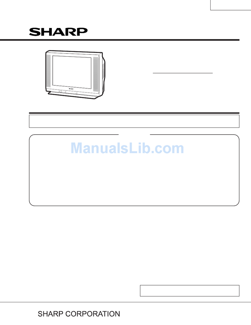
Sharp 29V-FT450S User manual

29V-FT95S
Service Manual
SHARP CORPORATION This document has been published to be used for after
sales service only.
The contents are subject to change without notice.
In the interests of user-safety (Required by safety regulations in some countries ) the set should be restored to its
original condition and only parts identical to those specified should be used.
COLOR TELEVISION
Chassis No. GB-5
Page
ELECTRICAL SPECIFICATIONS ......................................................................................................... 1
IMPORTANT SERVICE SAFETY PRECAUTION .................................................................................. 2
LOCATION OF USER'S CONTROL ..................................................................................................... 3
ADJUSTMENT PRECAUTION
SER
TROUBLESHOOTING FLOWCHART ................................................................................................. 26
VICE ADJUSTMENT ....................................................................................................................
CHASSIS LAYOUT ...............................................................................................................................34
BLOCK DIAGRAM ............................................................................................................................... 35
SCHEMATIC DIAGRAMS .................................................................................................................... 38
PRINTED WIRING BOARD ASSEMBLIES
REPLACEMENT PARTS LIST .............................................................................................................
PACKING OF THE SET .......................................................................................................................
CONTENTS
Specifications are subject to change without
prior notice.
SPEAKER
SIZE ......................................................................... 8 cm round
VOICE COIL IMPEDANCE ............................... 8 ohm at 400 Hz
ANTENNA INPUT IMPEDANCE
VHF/UHF ..................................................... 75 ohm Unbalanced
TUNING RANGES
VHF-Channels ...............................................................2 thru 13
UHF-Channels ............................................................ 14 thru 69
CATV Channels...........................................................1 thru 125
POWER INPUT ........................................ 110~240V AC, 50/60 Hz
POWER RATING .................................................................. 138W
PICTURE SIZE ....................................... 2,193.5 cm2 (339sq inch)
CONVERGENCE .................................. Self Convergence System
SWEEP DEFLECTION .................................................... Magnetic
FOCUS ............................................... Hi-Bi-Potential Electrostatic
INTERMEDIATE FREQUENCIES
Picture IF Carrier Frequency ..................................... 38.90 MHz
Sound IF Carrier Frequency ...................................... 34.40 MHz
Color Sub-Carrier Frequency .................................... 35.32 MHz
(Nominal)
AUDIO POWER
OUTPUT RATING .............. 7.5W + 7.5W (at 10% distortion and
Dual CH Operate)
ELECTRICAL SPECIFICATIONS
SERVICE MANUAL
29V-FT95S
TVSM062-29V-FT450S/29V-FT95S
.............................................................................................................. 4
20
..........................................................................................
43
40
50
29V-FT450S
29V-FT450S
29V-FT450S 29V-FT95S
29V-FT450S/29V-FT95S
2
TV29L-FG1MXService Manual29L-FG1MXMarketE
IMPORTANT SERVICE NOTES
Maintenance and repairing of this receiver should be done by
qualified service personnel only.
SERVICE OF HIGH VOLTAGE SYSTEM AND
PICTURE TUBE
When servicing the high voltage system, remove static charge from it by
connecting a 10K ohm resistor in series with an insulated wire (such as a test
probe) between picture tube dag and 2nd anode lead. (AC line cord should
be disconnected from AC outlet.)
1. Picture tube in this receiver employs integral implosion protection.
2. Replace with the same type number of picture tube for continued safety.
3. Do not lift picture tube by the neck.
4. Handle the picture tube only when wearing shatterproof goggles and after discharging
the high voltage completely.
X-RAY
This receiver is designed so that any X-Ray radiation is kept to an absolute
minimum. Since certain malfunctions or servicing may produce potentially
hazardous radiation with prolonged exposure at close range, the following
precautions should be observed:
1. When repairing the circuit, please make sure do not increase the high voltage of the set
to more then 34.0kV (at beam 0 A).
2. To keep the set in a normal operation, please make sure it's function at 30.0kV 1.5kV
(at beam 1700 A). The set has been factory - adjusted to the above-mentioned high voltage.
*If there is a possibility that the high voltage fluctuates as a result of the repaires,
never forget to check for such high voltage after the work.
3. Do not substitute a picture tube with unauthorized types and/or brands which may cause
excessive X-ray radiation.
BEFORE RETURNING THE RECEIVER
Before returning the receiver to the user, perform the following safety checks.
1. Inspect all lead dress to make certain that leads are not pinched or that hardware is not
lodged between the chassis and other metal parts in the receiver.
2. Inspect all protective devices such as non-metal control knobs, insulating fishpapers,
cabinet backs, adjustment and compartment covers or shields, isolation resistor- ca-
pacity networks, mechanical insulators etc.

3
LOCATION OF USER'S CONTROL
Front Panel
Basic Remote Control Functions
29V-FT450S/29V-FT95S
MAIN POWER
Press ON.
Press again
ON TIMER
REMOTE CONTROL
Sensor
VIDEO / AUDIO (AV-2 IN)
Input Terminal
VOLUME UP / DOWN
( ) Increases sound.
( ) Decreases sound.
MENU/PRESET
CHANNEL UP / DOWN
( ) Selects next higher channel
( ) Selects next lower channel.
Press either CH / CH
to turn the TV "ON".
Note : Appearance design may vary depending on model;
ON
TIMER
POWER
SAVE
TV/VIDEO
DISPLAY
SOUND MODE
SURROUND
NORMAL
TV
123
456
78
0
9
CH
CH
MENU
BACD
MTS
Infrared Transmitter Window
Aim this window at the infrared
sensor window on your TV set.
Press - Normal sound
Press 2 times - Surround sound
Mutes the sound and restores
sound to previous level.
Adjusts the volume.
Used for MENU setup.
Resets all settings.
Operate the Favourite Channel.
FAVOURITE CHANNEL
Press - displays receiving channel
Press again - removes display
REMOTE KEYPAD
Access any channel from keypad.
Returns to previously viewed
channel.
Selects the channel.
Used for MENU setup.
Calls the MENU screen.
Switches between TV broadcasts
and A/V input programmes.
Press - Power save is OFF
Press 2 times - Power save is ON
Turns the TV on or to
Standby mode.
TV/VIDEO
DISPLAY
MENU
CH
CH
NORMAL
//
POWER SAVE
Press - Stereo
Press 2 times - Mono
Press 3 times - SAP
Switches between MOVIE,
MUSIC, NEWS and CUSTOM.
SOUND MODE
SURROUND
MTS
•
MTS function selection is applicable only during Hi-Fi Stereo sound or SAP broadcast.
100

29V-FT450S/29V-FT95S
4
TV29L-FG1MXService Manual29L-FG1MXMarketE
ADJUSTMENT PRECAUTIONS
This model's setting are adjusted in two different ways: through the I2C bus control and in the
conventional analog manner. The adjustments via the I2C bus control include preset-only items and
variable data.
1. Setting the service mode by the microprocessor.
(1). Press and hold the local key "VOL DOWN" & "CH UP" when power on the main switch,
TV will enter into SERVICE MODE. (The initial values of EEPROM are automatically
preset when new EEPROM is used.)
(2). Press the CH DOWN / UP key on the remote controller to get ready to select the mode
one by one.
(3). Press the CH DOWN / UP key on the remote controller to select the modes reversibly
one by one.
(4). Using the VOLUME UP/ DOWN key on the remote controller, the data can be modified.
(5). Use the MENU key on the remote controller to select the mode as shown in the next page.
(6). When press the local key "VOL DOWN" & "CH UP" at the same time, it will be released
from the service mode.
2. Factory Presetting.
(1). After enter into the SERVICE MODE, at "INIT EEPROM" service item (which is under
"CHECK MODE" section) press remote controller key of code "ED", the initial values
are automatically preset.
(2). The initial data are preset as listed in page 4 to 15.
(3). Make sure whether the data need to modify or not (Initial data).
Note: Once the chassis has been assembly together and in ready condition, please make
sure it's gothroughinitializeprocess (see
page
2above)
Precaution: If haven't done this initialization, malfunction might be happen.

29V-FT450S/29V-FT95S
1) In the Service Mode, key is use to select the mode in the following order.
SETTING MODE 1
Picture
Setting
SETTING MODE 3
Audio
Setting
CHECK MODE
OPTION MODE
Function Setting
MENU button
of R/C
MENU button
of R/C
MENU button
of R/C
MENU button
of R/C
ADJUSTMENT MODE
RF AGC
50Hz/60Hz
GEOMETRIC ADJ
CUT OFF/
WHITE BALANCE ADJ
PICTURE
SUB ADJ
MENU button
of R/C
5

29V-FT450S/29V-FT95S
6
ADJUSTMENT MODE ITEMS SEQUENCE
Notes:
FORWARD : CH UP KEY
REVERSE : CH DOWN KEY
V SLOPE
H-PAR
EW-W-F60
E/W-PAR-F60
CUT-GW-DVD
DRI-BW-DVD
CUT-RW-DVD
DRI-RW-DVD
DRI-GW-DVD
CUT-RC-DVD
CUT-GC-DVD
DRI-GC-DVD
DRI-BC-DVD
CUT-GS-DVD
DRI-RC-DVD
CUT-RS-DVD
H-BOW
VER-SHI-P60
V-LIN
UPCOR-PAR
VER-SHI-F60
VER-AMP-F60
HOR-SHI-F60
S-COR
LOCOR-PAR
E/W-TRAP
V-SCROLL
VX-NORMAL
DRI-RS
DRI-GS
CUT-RS
DRI-BS
CUT-GS
DRI-RC
DRI-GC
DRI-BC
DRI-RW
CUT-RC
CUT-GC
DRI-GW
DRI-BW
CUT-RW
DRI-RS-DVD
CUT-GW
SUB-COL
SUB-CON
SUB-BRI
SUB-BRI-DVD
SUB-CON-DVD
SUB-TINT-DVD
SUB-TINT
SUB-SHARP
HOR-SHI-P60
VER-AMP-P60
DRI-BS-DVD
DRI-GS-DVD
VX-43COMP-P60
EW-W-P60
E/W-PAR-P60
GEOMETRIC
ADJ MODE
WHITE POINT
ADJ MODE
PICTURE SUB ADJ
MODE

29V-FT450S/29V-FT95S
7
OPTION MODE MENU
0001 Option Mode Picture Tube Used Type TUBE-TYPE
0002 PIF Frequency Setting PIF
0003 Sound M SND-M
0004 Sound DK SND-DK
0005 Sound I SND-I
0006 Sound BG SND-BG
0007 Colour System SECAM SECAM
0008 Colour System NTSC358 NTSC358
0009 Colour System NTSC443 NTSC443
0010 Audio Configuration AUDIO-CFG
0011 Mono Bilingual BILINGUAL
0012 Equalizer EQUALIZER
0013 Sub Woofer WOOFER
0014 Hotel Mode HOTEL
0015 Hotel Volume HTL-VOL
0016 Hotel Program Number HTL-PRG
0017 HTL-USE-LAST HTL-USE-LAST
0018 Childlock CHILD
0019 Wide Screen Signalling WSS
0020 Golden SCART GLD-SCART
0021 Power On Last Status PW-LAST
0022 AV1-IN AV1-IN
0023 Component Input DVD1-IN
0024 AV2-IN AV2-IN
0025 INCL-AV INCL-AV
0026 Reminder Timer TIM-REMINDER
0027 Off Timer TIM-OFF
0028 Commercial Skip Timer TIM-SKIP
0029 Virgin Mode VIRGIN MODE
0030 ERR-1-8-SUP ERR-1-8-SUP
0031 ERR-XRAY ERR-XRAY
0032 ERR-SUPVOL ERR-SUPVOL
0033 ERR-VERTG ERR-VERTG
0034 ARROW-ENTER-KEY ARROW-ENTER-KEY
0035 Teletext Pan-european TXTEURO-UNUSED
0036 Teletext Western TXTWEST-UNUSED
0037 Teletext On TXT ON-UNUSED
0038 Variable Audio Out
0039 BASS-EFFECT BASS-EFFECT
0040 TB-EFF-NOT-USED TREBLE-EFFECT
0041 SPANISH-NOT-USED SPANISH-NOT-USED
0042 DEMO-NOT-USED DEMO-NOT-USED
0043 Close Caption CC
0
0
VAO
0/1 0
00/1
1
1
0
0
1
1
0
0
0
1
0
0
0
1
1
1
1
1
1
1
0
1
1
1
0
30
1
0
1
INITIAL DATA
1
1
0
1
1
1
1
2
0
0/1
0/1
0/1
0..7
0/1
0/1
0/1
0..2
0/1
0/1
0/1
0/1
0...60
0...99
0/1
0/1
0/1
0/1
1
0..2
0/1
0/1
0/1
0/1
0/1
0/1
0
0/1
0/1
0/1
0/1
0/1
0/1
0/1
0
1
0
0/1
0/1
0/1
0/1
0/1
0/1
0/1
0
0
30
0
2
0
1
0
1
1
0
1
1
1
1
0
0
1
0
0
0
0
ITEM SERVICE MODE EEPROM ITEM OSD
0/1
0/1
DATA SETTING DATA
1
2
1
1
1
1
0
1
1
1
0
1
1
1
0
0
0

29V-FT450S/29V-FT95S
8
Adjustment Mode Items
A001 RF-AGC 0…63 UOC-TV RF-AGC 23 23
A002 V SLOPE 0…63 UOC-TV V SLOPE 35 *1
A003 VER-SHI-F50 0…63 UOC-TV VER-SHI-F50 39 *2
A004 VER-AMP-F50 0…63 UOC-TV VER-AMP-F50 35 *3
A005 HOR-SHI-F50 0…63 UOC-TV HOR-SHI-F50 31 *4
A006 EW-W-F50 0…63 UOC-TV EW-W-F50 11 *5
A007 E/W-PAR-F50 0…63 UOC-TV E/W-PAR-F50 32 *6
A008 H-PAR 0…63 UOC-TV H-PAR 30 30
A009 H-BOW 0…63 UOC-TV H-BOW 31 *7
A010 UPCOR-PAR 0…63 UOC-TV UPCOR-PAR 40 *8
A011 LOCOR-PAR 0…63 UOC-TV LOCOR-PAR 41 *9
A012 E/W-TRAP 0…63 UOC-TV E/W-TRAP 32 *10
A013 V-SCROLL 0…63 UOC-TV V-SCROLL 33 33
A014 VX-NORMAL 0…63 UOC-TV VX-NORMAL 25 25
A015 V-LIN 0…63 UOC-TV V-LIN 35 35
A016 S-COR 0…63 UOC-TV S-COR 32 32
A017 DRI-RS 0…63 UOC-TV DRI-RS 32 32
A018 DRI-GS 0…63 UOC-TV DRI-GS 32 32
A019 DRI-BS 0…63 UOC-TV DRI-BS 32 32
A020 CUT-RS 0…63 UOC-TV CUT-RS 32 32
A021 CUT-GS 0…63 UOC-TV CUT-GS 32 32
A022 SUB-BRI 0…63 UOC-TV SUB-BRI 34 34
A023 SUB-CON 0…63 UOC-TV SUB-CON 48 48
A024 SUB-COL 0…63 UOC-TV SUB-COL 10 26
A025 SUB-TINT 0…63 UOC-TV SUB-TINT 38 28
A026 SUB-SHARP 0…63 UOC-TV SUB-SHARP 32 32
A027 DRI-RS-DVD 0…63 UOC-TV DRI-RS-DVD 32 32
A028 DRI-GS-DVD 0…63 UOC-TV DRI-GS-DVD 32 32
A029 DRI-BS-DVD 0…63 UOC-TV DRI-BS-DVD 32 32
A030 CUT-RS-DVD 0…63 UOC-TV CUT-RS-DVD 32 32
A031 CUT-GS-DVD 0…63 UOC-TV CUT-GS-DVD 32 32
A032 SUB-BRI-DVD 0…63 UOC-TV SUB-BRI-DVD 35 35
A033 SUB-CON-DVD 0…63 UOC-TV SUB-CON-DVD 48 48
A034 SUB-TINT-DVD 0…63 UOC-TV SUB-TINT-DVD 32 32
A035 DRI-RC 0…63 UOC-TV DRI-RC 32 32
OSD INITIAL DATA SETTING DATAItem EEPROM SETTING DATA RANGE IC

29V-FT450S/29V-FT95S
9
A036 DRI-GC 0…63 UOC-TV DRI-GC 32 32
A037 DRI-BC 0…63 UOC-TV DRI-BC 32 32
A038 CUT-RC 0…63 UOC-TV CUT-RC 32 32
A039 CUT-GC 0…63 UOC-TV CUT-GC 32 32
A040 DRI-RW 0…63 UOC-TV DRI-RW 32 32
A041 DRI-GW 0…63 UOC-TV DRI-GW 32 32
A042 DRI-BW 0…63 UOC-TV DRI-BW 32 32
A043 CUT-RW 0…63 UOC-TV CUT-RW 32 32
A044 CUT-GW 0…63 UOC-TV CUT-GW 32 32
A045 DRI-RC-DVD 0…63 UOC-TV DRI-RC-DVD 32 32
A046 DRI-GC-DVD 0…63 UOC-TV DRI-GC-DVD 32 32
A047 DRI-BC-DVD 0…63 UOC-TV DRI-BC-DVD 32 32
A048 CUT-RC-DVD 0…63 UOC-TV CUT-RC-DVD 32 32
A049 CUT-GC-DVD 0…63 UOC-TV CUT-GC-DVD 32 32
A050 DRI-RW-DVD 0…63 UOC-TV DRI-RW-DVD 32 32
A051 DRI-GW-DVD 0…63 UOC-TV DRI-GW-DVD 32 32
A052 DRI-BW-DVD 0…63 UOC-TV DRI-BW-DVD 32 32
A053 CUT-RW-DVD 0…63 UOC-TV CUT-RW-DVD 32 32
A054 CUT-GW-DVD 0…63 UOC-TV CUT-GW-DVD 32 32
A055 VER-SHI-N50 0…63 UOC-TV VER-SHI-N50 15 15
A056 VER-AMP-N50 0…63 UOC-TV VER-AMP-N50 28 28
A057 HOR-SHI-N50 0…63 UOC-TV HOR-SHI-N50 44 44
A058 EW-W-N50 0…63 UOC-TV EW-W-N50 29 29
A059 E/W-PAR-N50 0…63 UOC-TV E/WPAR-N50 25 25
A060 VER-SHI-S50 0…63 UOC-TV VER-SHI-S50 13 13
A061 VER-AMP-S50 0…63 UOC-TV VER-AMP-S50 22 22
A062 HOR-SHI-S50 0…63 UOC-TV HOR-SHI-S50 44 44
A063 EW-W-S50 0…63 UOC-TV EW-W-S50 29 29
A064 E/W-PAR-S50 0…63 UOC-TV E/W-PAR-S50 22 22
A065 SUB-SCROLL-S 0…63 UOC-TV SUB-SCROLL-S 31 31
A066 SUB-VX-S50 0…63 UOC-TV SUB-VX-S50 43 43
A067 VER-SHI-C50 0…63 UOC-TV VER-SHI-C50 14 14
A068 VER-AMP-C50 0…63 UOC-TV VER-AMP-C50 23 23
A069 HOR-SHI-C50 0…63 UOC-TV HOR-SHI-C50 44 44
A070 EW-W-C50 0…63 UOC-TV EW-W-C50 29 29
Item EEPROM SETTING DATA RANGE IC OSD INITIAL DATA SETTING DATA

29V-FT450S/29V-FT95S
A071 E/W-PAR-C50 0…63 UOC-TV E/W-PAR-C50 22 22
A072 SUB-SCROLL-C 0…63 UOC-TV SUB-SCROLL-C 31 31
A073 SUB-VX-C50 0…63 UOC-TV SUB-VX-C50 49 49
A074 VER-SHI-P50 0…63 UOC-TV VER-SHI-P50 39 *11
A075 VER-AMP-P50 0…63 UOC-TV VER-AMP-P50 35 *12
A076 HOR-SHI-P50 0…63 UOC-TV HOR-SHI-P50 31 *13
A077 EW-W-P50 0…63 UOC-TV EW-W-P50 11 *14
A078 E/W-PAR-P50 0…63 UOC-TV E/W-PAR-P50 32 *15
A079 VX-43COMP-P50 0…63 UOC-TV VX-43COMP-P50 5 5
A080 VER-SHI-F60 0…63 UOC-TV VER-SHI-PF0 36 *16
A081 VER-AMP-F60 0…63 UOC-TV VER-AMP-F60 37 *17
A082 HOR-SHI-F60 0…63 UOC-TV HOR-SHI-F60 37 *18
A083 EW-W-F60 0…63 UOC-TV EW-W-F60 10 *19
A084 E/W-PAR-F60 0…63 UOC-TV E/W-PAR-F60 34 *20
A085 VER-SHI-N60 0…63 UOC-TV VER-SHI-N60 13 13
A086 VER-AMP-N60 0…63 UOC-TV VER-AMP-N60 29 29
A087 HOR-SHI-N60 0…63 UOC-TV HOR-SHI-N60 46 46
A088 EW-W-N60 0…63 UOC-TV EW-W-N60 29 29
A089 E/W-PAR-N60 0…63 UOC-TV E/W-PAR-N60 22 22
A090 VER-SHI-S60 0…63 UOC-TV VER-SHI-S60 12 12
A091 VER-AMP-S60 0…63 UOC-TV VER-AMP-S60 20 20
A092 HOR-SHI-S60 0…63 UOC-TV HOR-SHI-S60 52 52
A093 EW-W-S60 0…63 UOC-TV EW-W-S60 28 28
A094 E/W-PAR-S60 0…63 UOC-TV E/W-PAR-S60 22 22
A095 SUB-VX-S60 0…63 UOC-TV SUB-VX-S60 45 45
A096 VER-SHI-C60 0…63 UOC-TV VER-SHI-C60 11 11
A097 VER-AMP-C60 0…63 UOC-TV VER-AMP-C60 20 20
A098 HOR-SHI-C60 0…63 UOC-TV HOR-SHI-C60 51 51
A099 EW-W-C60 0…63 UOC-TV EW-W-C60 29 29
A100 E/W-PAR-C60 0…63 UOC-TV E/W-PAR-C60 22 22
A101 SUB-VX-C60 0…63 UOC-TV SUB-VX-C60 51 51
A102 VER-SHI-P60 0…63 UOC-TV VER-SHI-P60 36 *21
A103 VER-AMP-P60 0…63 UOC-TV VER-AMP-P60 37 *22
A104 HOR-SHI-P60 0…63 UOC-TV HOR-SHI-P60 37 *23
A105 EW-W-P60 0…63 UOC-TV EW-W-P60 10 *24
A106 E/W-PAR-P60 0…63 UOC-TV E/W-PAR-P60 30 *25
A107 VX-43COMP-P60 0…63 UOC-TV VX-43COMP-P60 5 5
A108 VSD 0/1 UOC-TV VSD 0 0
A109 CUT OFF 0…63 UOC-TV CUT OFF 11 13
A110 VG2 0/1 UOC-TV VG2 0 0
A111 DCXO 0…127 UOC-SSD DCXO 57 76
A112 DCXO-AUTO 0/1 UOC-SSD DCXO-AUTO 0 0
OSD INITIAL DATA SETTING DATAItem EEPROM SETTING DATA RANGE IC
10

29V-FT450S/29V-FT95S
SETTING DATA PATTERN FOR DIFFERENT CRT
SETTING
DATA LG CRT MTPD CRT SAMSUNG CRT
*1 A002 35 35 30
*2 A003 39 31 32
*3 A004 35 22 35
*4 A005 31 35 35
*5 A006 11 23 25
*6 A007 32 50 55
*7 A009 31 31 27
*8 A010 40 45 40
*9 A011 41 46 41
*10 A012 32 32 30
*11 A074 39 31 35
*12 A075 35 22 35
*13 A076 31 35 35
*14 A077 11 23 25
*15 A078 32 50 55
*16 A080 36 30 35
*17 A081 37 25 37
*18 A082 37 40 35
*19 A083 10 22 25
*20 A084 34 50 55
*21 A102 36 30 35
*22 A103 37 25 37
*23 A104 37 40 35
*24 A105 10 22 25
*25 A106 30 50 55
HOR-SHI-F60
EW-W-F60
E/W-PAR-F60
E/W-PAR-P60
VER-SHI-P60
VER-AMP-P60
HOR-SHI-P60
EW-W-P60
EW-W-P50
E/W-PAR-P50
VER-SHI-F60
VER-AMP-F60
E/W-TRAP
VER-SHI-P50
VER-AMP-P50
HOR-SHI-P50
E/W-PAR-F50
H-BOW
UPCOR-PAR
LOCOR-PAR
VER-SHI-F50
VER-AMP-F50
HOR-SHI-F50
EW-W-F50
ITEM
EEPROM
SETTING
V SLOPE
SETTING DATA
11

29V-FT450S/29V-FT95S
12
ITEM IC INITIAL DATA SETTING DATA
S001 UOC-TV 00
S002 UOC-TV 32 32
S003 UOC-TV 1 3
S004 UOC-TV 12 14
S005 UOC-TV 1 0
S006 UOC-TV 1 1
S007 UOC-TV 0 0
S008 UOC-TV 0 1
S009 UOC-TV 11 11
S010 UOC-TV 11 11
S011 UOC-TV 9 9
S012 UOC-TV 7 7
S013 UOC-TV 7 7
S014 UOC-TV 7 7
S015 UOC-TV 7 7
S016 UOC-TV 7 7
S017 UOC-TV 7 7
S018 UOC-TV 7 7
S019 UOC-TV 7 7
S020 UOC-TV 7 7
S021 UOC-TV 7 7
S022 UOC-TV 7 7
S023 UOC-TV 7 7
S024 UOC-TV 7 7
S025 UOC-TV 1 1
S026 UOC-TV 1 1
S027 UOC-TV 0 0
S028 UOC-TV 1 1
S029 UOC-TV 1 1
S030 UOC-TV 1 1
S031 UOC-TV 1 1
S032 UOC-TV 1 1
S033 UOC-TV 0 0
S034 UOC-TV 1 1
S035 UOC-TV 7 7
S036 UOC-TV 1 1
S037 UOC-TV 1 1
S038 UOC-TV 0 0
S039 UOC-TV 1 1
S040 UOC-TV 1 0
S041 UOC-TV 1 0
S042 UOC-TV 1 0
0…63 IFPLL
0…3 SOC1-0
DATA RANGE OSD
0…2 V-LINCTRL
EEPROM SETTING
V-LINCTRL
IFPLL
SOC1-0
WHITE LMT 0…15 WHITE LMT
GD 0/1 GD
AGC0-1 0…3 AGC0-1
FFI 0/1 FFI
CFA0 0/1 CFA0
YD PAL 0…15 YD PAL
YD SECAM 0…15 YD SECAM
YD N358 0…15 YD N358
YD N443 0…15 YD N443
YD AV-PAL 0…15 YD AV-PAL
YD AV-SECAM 0…15 YD AV-SECAM
YD AV-N358 0…15 YD AV-N358
YD AV-N443 0…15 YD AV-N443
YD SAV-PAL 0…15 YD SAV-PAL
YD SAV-SECAM 0…15 YD SAV-SECAM
YD SAV-N358 0…15 YD SAV-N358
YD SAV-N443 0…15 YD SAV-N443
YD COMP-PAL 0…15 YD COMP-PAL
YD COMP-SECAM 0…15 YD COMP-SECAM
YD COMP-N358 0…15 YD COMP-N358
YD COMP-N443 0…15 YD COMP-N443
SBO1-0 0…3 SBO1-0
CHSE1-0 0…3 CHSE1-0
FCO 0/1 FCO
OSO 0/1 OSO
DFL 0/1 DFL
EVG 0/1 EVG
HCO 0/1 HCO
SVMA 0/1 SVMA
FBC 0/1 FBC
SLG1-0 0…3 SLG1-0
CL3-0 0…15 CL3-0
GAM 0/1 GAM
TFR 0/1 TFR
CLD 0/1 CLD
BKS 0/1 BKS
BSD 0/1 BSD
AAS1-0 0…3 AAS1-0
DSK-NOT-PAL-AV 0/1 DSK-NOT-PAL-AV
SETTING MODE 1

29V-FT450S/29V-FT95S
13
ITEM IC INITIAL DATA SETTING DATA
S043 UOC-TV 0 1
S044 UOC-TV 0 0
S045 UOC-TV 1 0
S046 UOC-TV 0 0
S047 UOC-TV 3 2
S048 UOC-TV 1 3
S049 UOC-TV 0 0
S050 UOC-TV 2 2
S051 UOC-TV 5 5
S052 UOC-TV 3 0
S053 UOC-TV 0 1
S054 UOC-TV 0 0
S055 UOC-TV 0 0
S056 UOC-TV 1 1
S057 UOC-TV 0 0
S058 UOC-TV 1 1
S059 UOC-TV 3 3
S060 UOC-TV 45 32
S061 UOC-TV 46 39
S062 UOC-TV 45 41
S063 UOC-TV 40 31
S064 UOC-TV 31 31
S065 UOC-TV 31 31
S066 UOC-TV 46 31
S067 UOC-TV 23 23
S068 UOC-TV 49 43
S069 UOC-TV 35 43
S070 UOC-TV 35 35
S071 UOC-TV 31 31
S072 UOC-TV 31 31
S073 UOC-TV 40 40
S074 UOC-TV 31 34
S075 UOC-TV 34 37
S076 UOC-TV 32 34
S077 UOC-TV 31 31
S078 UOC-TV 32 32
S079 UOC-TV 0 0
S080 UOC-TV 1 1
S081 UOC-TV 1 1
S082 UOC-TV 1 1
S083 UOC-TV 3 3
S084 UOC-TV 1 1
BLS 0/1 BLS
EEPROM SETTING DATA RANGE OSD
LLB 0/1 LLB
DSA 0/1 DSA
RPA1-0 0…2 RPA1-0
RPO1-0 0…3 RPO1-0
COR1-0 0…3 COR1-0
CRA0 0/1 CRA0
SPR2-0 0…6 SPR2-0
SVM2-0-PAL 0…7 SVM2-0-PAL
SMD1-0 0…3 SMD1-0
PEAKFREQPAL443 0…3 PEAKFREQPAL443
PEAKFREQPALM 0…3 PEAKFREQPALM
PEAKFREQPALN 0…3 PEAKFREQPALN
PEAKFREQNTSC443 0…3 PEAKFREQNTSC443
PEAKFREQNTSCM 0…3 PEAKFREQNTSCM
PEAKFREQSECAM 0…3 PEAKFREQSECAM
PEAKFREQDVD 0…3 PEAKFREQDVD
OF-COL-TV 0…31…62 OF-COL-TV
OF-COL-AV 0…31…62 OF-COL-AV
OF-COL-DVD 0…31…62 OF-COL-DVD
OF-COL-P 0…31…62 OF-COL-P
OF-COL-S 0…31…62 OF-COL-S
OF-COL-N4 0…31…62 OF-COL-N4
OF-COL-N3 0…31…62 OF-COL-N3
OF-SHP-TV 0…31…62 OF-SHP-TV
OF-SHP-AV 0…31…62 OF-SHP-AV
OF-SHP-DVD 0…31…62 OF-SHP-DVD
OF-SHP-P 0…31…62 OF-SHP-P
OF-SHP-S 0…31…62 OF-SHP-S
OF-SHP-N4 0…31…62 OF-SHP-N4
OF-SHP-N3 0…31…62 OF-SHP-N3
OF-TINT-TV 0…31…62 OF-TINT-TV
OF-TINT-AV 0…31…62 OF-TINT-AV
OF-TINT-DVD 0…31…62 OF-TINT-DVD
OF-TINT-ADJ 0…31…62 OF-TINT-ADJ
BB-TINT 0…63 BB-TINT
VMA-SOFT 0…3 VMA-SOFT
WS-SOFT 0…3 WS-SOFT
VMA-STD 0…3 VMA-STD
WS-STD 0…3 WS-STD
VMA-DYN 0…3 VMA-DYN
WS-DYN 0…3 WS-DYN

29V-FT450S/29V-FT95S
ITEM IC INITIAL DATA SETTING DATA
S085 UOC-TV 2 2
S086 UOC-TV 1 1
S087 UOC-TV 25 25
S088 UOC-TV 31 31
S089 UOC-TV 36 36
S090 UOC-TV 50 50
S091 UOC-TV 60 60
S092 UOC-TV 60 60
S093 UOC-TV 26 26
S094 UOC-TV 31 31
S095 UOC-TV 36 36
S096 UOC-TXT 25 25
S097 UOC-TXT 18 18
S098 UOC-TXT 48 37
S099 UOC-TXT 0 0
S100 UOC-TXT 10 10
S101 UOC-MCU 1 1
S102 UOC-MCU 3 3
S103 UOC-MCU 0 0
S104 UOC-MCU 1 1
S105 UOC-TV 3 3
S106 UOC-TV 0 0
S107 UOC-TV 0 0
S108 UOC-TV 1 1
S109 UOC-TV 1 0
S110 UOC-TV 0 0
S111 UOC-TV 3 3
S112 UOC-TV 2 2
S113 UOC-TV 1 1
S114 UOC-TV 4 3
S115 UOC-TV 4 7
S116 UOC-TV 3 3
S117 UOC-TV 4 7
S118 UOC-TV 11 3
S119 UOC-TV 8 7
S120 UOC-TV 0 6
S121 UOC-TV 4 13
S122 UOC-TV 0 6
S123 UOC-TV 5 13
S124 UOC-TV 6 6
S125 UOC-TV 10 13
S126 UOC-TV 0 0
0…31…62 U-COL-STD
VMA-CTM 0…3 VMA-CTM
WS-CTM 0…3
U-COL-DYN 0…31…62 U-COL-DYN
U-COL-STD
EEPROM SETTING DATA RANGE OSD
U-COL-SOFT 0…31…62 U-COL-SOFT
WS-CTM
U-CON-SOFT 0…60 U-CON-SOFT
U-CON-STD 0…60 U-CON-STD
U-CON-DYN 0…60 U-CON-DYN
U-SHP-SOFT 0…31…62 U-SHP-SOFT
U-SHP-STD 0…31…62 U-SHP-STD
U-SHP-DYN 0…31…62 U-SHP-DYN
OSD-BRIGHTNESS 0…31 OSD-BRIGHTNESS
V-POS-CURTAIN 0…63 V-POS-CURTAIN
V-POS-OSD 0…63 V-POS-OSD
H-POS-FINE 0…3 H-POS-FINE
H-POS-OSD 0…63 H-POS-OSD
PW-SAVING 0/1 PW-SAVING
PW-TIME 0…3 PW-TIME
I-TIME 0…3 I-TIME
PHI FORCE 0...1 PHI FORCE
PHI 0…3 PHI
BPD 0/1 BPD
E2D 0/1 E2D
ACL 0/1 ACL
MAT 0/1 MAT
CB 0/1 CB
SVM-OSD-PW 0…3 SVM-OSD-PW
SMD-OSD-TM 0…7 SMD-OSD-TM
XDT 0/1 XDT
WBF-50-F-C-P 0…15 WBF-50-F-C-P
WBR-50-F-C-P 0…15 WBR-50-F-C-P
WBF-50SUBTITLE 0…15 WBF-50SUBTITLE
WBR-50-SUBTITLE 0…15 WBR-50-SUBTITLE
WBF-50-OTHER 0…15 WBF-50-OTHER
WBR-50-OTHER 0…15 WBR-50-OTHER
WBF-60-F-C-P 0…15 WBF-60-F-C-P
WBR-60-F-C-P 0…15 WBR-60-F-C-P
WBF-60SUBTITLE 0…15 WBF-60SUBTITLE
WBR-60-SUBTITLE 0…15 WBR-60-SUBTITLE
WBF-60-OTHER 0…15 WBF-60-OTHER
WBR-60-OTHER 0…15 WBR-60-OTHER
FSL 0/1 FSL
14

29V-FT450S/29V-FT95S
15
ITEM IC INITIAL DATA SETTING DATA
S127 UOC-TV 0 0
S128 UOC-TV 15 20
S129 UOC-TV 14 20
S130 UOC-TV 12 18
S131 UOC-TV 15 10
S132 UOC-TV 5 5
S133 UOC-TV 0 0
S134 UOC-TV 1 1
S135 UOC-TV 25 34
S136 UOC-TV 1 0
S137 UOC-TV 31 31
S138 UOC-TXT 0 0
S139 UOC-TXT 0 0
S140 UOC-TXT 0 0
S141 UOC-TXT 0 0
S142 UOC-TXT 0 0
S143 UOC-TV 0 0
S144 UOC-TV 0 0
S145 UOC-TV 1 0
S146 UOC-TV 1 0
S147 UOC-TV 0 1
S148 UOC-TV 1 1
HP2 0/1 HP2
GAIN-RED 0…127 GAIN-RED
GAIN-GREEN 0…127 GAIN-GREEN
GAIN-BLUE 0…127 GAIN-BLUE
AUTO-AGC-MAX 0…32 AUTO-AGC-MAX
SVM2-0-NTSC
IFO-TV-MODE 0…7 IFO-TV-MODE
0..7SVM2-0-NTSC
0…62 COL-DVD-PAL
PWL 0/1 PWL
VER-AMP-START 0…63 VER-AMP-START
VPTXT-UNUSED 0…63 VPTXT-UNUSED
EEPROM SETTING DATA RANGE OSD
DSK-PAL-AV 0/1 DSK-PAL-AV
COL-DVD-PAL
HPTXT1-UNUSED 0…63 HPTXT1-UNUSED
HPTXT2A-UNUSED 0…63 HPTXT2A-UNUSED
HPTXT2B-UNUSED 0…63 HPTXT2B-UNUSED
BOXBPOS-UNUSED 0…127 BOXBPOS-UNUSED
EW-TXT-UNUSED 0…63 EW-TXT-UNUSED
H-SHI-UNUSED 0…63 H-SHI-UNUSED
DSK-PAL-DVD 0/1 DSK-PAL-DVD
DSK-NOT-PAL-DVD 0/1 DSK-NOT-PAL-DVD
MUS-NTSC-MAT 0/1 MUS-NTSC-MAT
DTRC-TRAP 0/1 DTRC-TRAP

29V-FT450S/29V-FT95S
16
SETTING MODE 3
ITEM EEPROM SETTING DATA RANGE IC OSD INITIAL DATA SETTING DATA
S301 FMI 0/1 DSP FMI 0 0
S302 BPB 0/1 DSP BPB 0 0
S303 BPB2 0/1 DSP BPB2 1 1
S304 FILTBW-M 0…3 DSP FILTBW-M 0 0
S305 ID-BYBPF 0/1 DSP ID-BYBPF 0 0
S306 ID-PGAIN 0/1 DSP ID-PGAIN 0 0
S307 MPX-P-BW 0/1 DSP MPX-P-BW 0 0
S308 FMSUB-BW 0/1 DSP FMSUB-BW 0 0
S309 EIAJ-DEL 0…3 DSP EIAJ-DEL 0 0
S310 NDETPB 0/1 DSP NDETPB 0 0
S311 NICDEEM 0/1 DSP NICDEEM 0 0
S312 NLOERLIM 0…255 DSP NLOERLIM 100 100
S313 NUPERLIM 0…255 DSP NUPERLIM 200 200
S314 FILTBW 0…3 DSP FILTBW 0 0
S315 OVMTHR 0…3 DSP OVMTHR 1 1
S316 DECLEV 0...31 DSP DECLEV 16 11
S317 MONOLEV 0...31 DSP MONOLEV 16 11
S318 NICLEV 0...31 DSP NICLEV 16 18
S319 SAPLEV 0...31 DSP SAPLEV 16 6
S320 ADCLEV 0...31 DSP ADCLEV 16 15
S321 IISLEV 0...31 DSP IISLEV 16 16
S322 MAINLOUD 0/1 DSP MAINLOUD 0 0
S323 MAINLONA 0...7 DSP MAINLONA 0 0
S324 MAINLOCH 0...3 DSP MAINLOCH 0 0
S325 INSOEF 0...7 DSP INSOEF 3 3
S326 AVLMOD 0...7 DSP AVLMOD 0 5
S327 AVLWGT 0/1 DSP AVLWGT 1 1
S328 AVLLE 0…15 DSP AVLLE 7 8
S329 CLIPMANAGE 0…4 DSP CLIPMANAGE 0 3
S330 VDSMIXLEV 0…5 DSP VDSMIXLEV 3 3
S331 DBEADR 0…63 DSP DBEADR 0 0
S332 DBECOEF-LBS 0…255 DSP DBECOEF-LBS 0 0
S333 DBECOEF-MBS 0…15 DSP DBECOEF-MBS 0 0
S334 DUBADR 0…255 DSP DUBADR 0 0
S335 DUBCOEF-LSB 0…255 DSP DUBCOEF-LBS 0 0
S336 DUBCOEF-MSB 0…15 DSP DUBCOEF-MBS 0 0

29V-FT450S/29V-FT95S
17
ITEM EEPROM SETTING DATA RANGE IC OSD INITIAL DATA SETTING DATA
S337 BAMAMO 0…3 DSP BAMAMO 0 0
S338 BAMASUB 0/1 DSP BAMASUB 0 0
S339 BAMAFC 0…15 DSP BAMAFC 0 11
S340 BASS-MV 0...31 DSP BASS-MV 16 23
S341 TREB-MV 0...31 DSP TREB-MV 16 21
S342 EQ100-MV 0...31 DSP EQ100-MV 12 21
S343 EQ300-MV 0...31 DSP EQ300-MV 12 15
S344 EQ1K-MV 0...31 DSP EQ1K-MV 12 20
S345 EQ3K-MV 0...31 DSP EQ3K-MV 12 15
S346 EQ8K-MV 0...31 DSP EQ8K-MV 12 21
S347 BASS-MS 0...31 DSP BASS-MS 16 23
S348 TREB-MS 0...31 DSP TREB-MS 16 21
S349 EQ100-MS 0...31 DSP EQ100-MS 12 20
S350 EQ300-MS 0...31 DSP EQ300-MS 12 16
S351 EQ1K-MS 0...31 DSP EQ1K-MS 12 11
S352 EQ3K-MS 0...31 DSP EQ3K-MS 12 16
S353 EQ8K-MS 0...31 DSP EQ8K-MS 12 20
S354 BASS-NW 0...31 DSP BASS-NW 16 23
S355 TREB-NW 0...31 DSP TREB-NW 16 21
S356 EQ100-NW 0...31 DSP EQ100-NW 12 11
S357 EQ300-NW 0...31 DSP EQ300-NW 12 16
S358 EQ1K-NW 0...31 DSP EQ1K-NW 12 21
S359 EQ3K-NW 0...31 DSP EQ3K-NW 12 16
S360 EQ8K-NW 0...31 DSP EQ8K-NW 12 11
S361 BASS-CT 0...31 DSP BASS-CT 16 23
S362 TREB-CT 0...31 DSP TREB-CT 16 21
S363 IDMOD-SE 0…3 DSP IDMOD-SE 0 0
S364 BPR-VOL 0…60 DSP BPR-VOL 45 30
S365 DEMUT-DLAY 0…15 DSP DEMUT-DLAY 8 8
S366 AV-OUT LV 0 .. 255 DSP AV-OUT LV 16 10
S367 FMWS-1-0-TV 0...3 DSP FMWS-1-0-TV 11
S368 BASSON 0/1 DSP BASSON 00
S369 EQ-OFFSET 0/1 DSP EQ-OFFSET 00
S370 VAO-LV 0…60 DSP VAO-LV 060

29V-FT450S/29V-FT95S
18
(1) The following default data has been factory-setting for the EEPROM.
Model-Set: The data in table below (1.1), Model set overview is updated to the respective EEPROM location base on
RC key input Model Set 1.
MODEL-SET KEY
1
Default Settings
Note : * The CHILD LOCK PASSWORD and VIEW TIMER PASSWORD are common use.
*AFTalwaysON
* Colour Systems always NTSC M
* Sound System always NTSC M (mono), BTSC M (stereo)
* No MCL feature, all channel frequency is fixed. (Refer to US channel plan : AIR, IRC, HRC, STD)
* Model set key ( model set 1) will not affect channel frequency (all refer to US channel plan)
WHITE TEMP
BRIGHTNESS
SOUND menu
+6
0
0
SURROUND
EPS
BALANCE
0
PICTURE menu
VIDEO MODE
DYNAMIC
60
CONTRAST
TINT
EQUALIZER menu
MOVIE
INSET menu (for PIP model)
0
0
MODE
MODE
FULL
V-SCROLL
0
0
V-SIZE
FEATURE menu
Cable Type
AIR
CH SETTING menu
PASSWORD
BEEP REMINDER
OFF
SKIP
BBE
ON
BASS+
ON
AVL
ON
VOLUME
__
VIEW TIMER menu
REMINDER
__:__
+6
WIDE MODE menu
OFF TIMER
__:__
VIEWING TIME
__:__
All Programs OFF
0000
LOCK
OFF
0000
0 (CENTER)
PICTURE NR
OFF
VIRGIN mode
ON
COLOUR
BRIGHTNESS
TINT
SHARPNESS
POSITION
__
OFF
CHILD LOCK menu
LOCK STATUS
OFF
ON TIMER
__:__
TIMER menu
PASSWORD
SAP mode
All Programs MAIN
MTS MONO mode
Volume
0
All Programs MONO
MTS STEREO mode
All Programs STEREO
Program 30
100 key digit entry
2 digit entry
16:9 MODE
OFF
Favorite Program D
Program 40
OFF
Favorite Program B
Program 20
Favorite Program A
Program 10
ROTATION
0
OFF
AUTO SELECT
ON
POWER SAVE
OFF
OFF
Flashback Program-TV
Program 2
Last TV/AV mode
TV mode
Last position-TV
Program 2
Last power
ON
COMFY VIEW
SHIPPING SETTING & CHECKING
OSD LANGUAGE
English
Default Settings
GENERAL
Items
Default Settings
Items
SAFETY MODE
Favorite Program C
BLUE BACK
LOCK TV
For model Set 1, the respective
EEPROM position is updated
again with the data attached at the
back

29V-FT450S/29V-FT95S
19
(1) Refer to below table (2.1) for setting of each destination.
MODEL LANGUAGE S-SYS
PHILIPPINES 10,000 39,000 ENGLISH M
Table 2.1
(2) refer to below table (2.2) for Normal setting of each AV mode.
MODE
CONTRAST
COLOUR
BRIGHTNESS
TINT
SHARPNESS
PICTURE NR
WHITE TEMP.
Table 2.2
15000K
STANDARD
1
60
+1
0
0
MAGNETIC FIELD (V,H)nT BACKGROUND
0 (center)
+6
0 (center)
OFFOFF
0 (center)
0
0
0
OFF
FACTORY SET
-4
MODEL SET 1
60
+6
DYNAMIC SOFT
50
-4
0

29V-FT450S/29V-FT95S
20
ADJUSTMENT
PIF ADJUSTMENT CHECKING
N
O ADJUSTMENT POINT ADJUSTMENT CONDITION / PROCEDURE WAVEFORM OR REMARKS
1 RF-AGC (1) Receive "US 10CH HALF COLOR BAR" signal
TAKE OVER POINT Signal Strength: 56 ± 1dBµV (75 ohm termination) Confirmation Voltage : 3.6 ± 0.4 VDC
ADJUSTMENT Monitor point : TP53
(I2C BUS CONTROL) Manual Adjustment
(2) Connect the oscilloscope to TP53 (Tuner's AGC Terminal) as shown in figure 3-1.
OSCILLOSCOPE
BIAS BOX
TV SET
Bias Box : about 4.5V
Fig. 3
(3) Select "RF-AGC" item in the Adjustment Mode. Adjust the "RF-AGC"
bus data to obtain the Tuner output pin dro
p
0.1V ~1.0V below maximum voltage
Auto Adjustment
(4) Select "RF-AGC" item in the Adjustment Item. Push the RF-AGC button, blue display with
OK sign indicates the adjustment is working properly.
(5) Change the antenna input signal to 63 ~ 67dBµV, and make sure there is no noise.
(6)Turn up the input signal to 90 ~ 95 dBµB to be sure that there is no cross modulation beat.
PURITY ADJUSTMENT
N
O ADJUSTMENT POINT ADJUSTMENT CONDITION / PROCEDURE WAVEFORM OR REMARKS
1 PURITY ADJ. (1) Select the green monocolor screen with remote contoller, and set the beam current of
1.7mA with the contrast control.
(2) Degauss the CRT enough with the degausing coil. a b
NOTE: Follow the job instruction manual to adjust the magnetic field.
(3) The purity magnet must be previously set at the 0 magnetic field, and the
convergence must be adjusted to be rough. 90 mm 90mm
With P-MAG, adjust it to the center - rank A. Fig. 1 -1
(4) Observe the points a,b, as shown in Fig.1-1 through the microscope.
Move DY fore and aft to set the landing at the point (Rank A).
(5) If the a/b balance is poor, compensate it to the center "Rank AB".
(6) Aline it to zero, keeping the raster rotation in the east direction. A
(7) Tighten the deflection coil fastening screws. A=B
Tightening torque : 108N ± 20N ( 11Kgf ± 2Kgf
)
B
(8) Checking the CRT corner area, bond the magnetic sheet to set the landing at
rank A for compensation.
Fig 1 -2 . Rank A (On the right of CRT)
Note: Apply the adjustment after aging with the beam current 1700±50µA or more
for 30 minutes or more.
Note: Select the service mode, and press the monocolor key of R/C for process, A
and the monocolor screen (green) will be selected. A=B
B
* Every push of the monocolor key, changes the screen as follows.
Fig. 1 - 3 . Rank A (On the left of CRT).
*Continuously press the monocolor key
1 second or more, and the monocolor mode
will be selected without the service mode.
*Even with TEXT key or "R/G/B" key,
it can be directly switched to each monocolor
screen.
2 UNIFORMITY Before adjustment begin,Horizontal magnetic field = 0G
ADJUSTMENT Vertical magnetic field = Each destination's adjustment magnetic field
(To perform after the Make sure to degauss it.
purity and
convergence (North direction red uniformity)
adjustment) (1) Horizontal mf = Set to monocolor screen red and adjust to +0.20G.
(2) Pay attention to the edge of CRT,if the landing is poor adjust by attaching the
the compensation magnet at the back of CRT. (CRT surface)
(refer to Fig-1)
Mislanding
(South direction red uniformity)
(1) Horizontal mf = Set to monocolor screen red and adjust to -0.20G.
(2) Pay attention to the edge of CRT ,if the landing is poor adjust by attaching t
h
compensation magnet at the back of CRT.
(The same method is applied for adjustment of monocolor screen blue for
blue uniformity ,and changing both the magnetic field for north and south
direction.) (CRT back)
*During the pasting of compensation magnet , use the crosshatch pattern . compensation magnet
Make sure there is no blur or bendlines occur.
If the blur or bend are serious,adjust the location of compensation magnet Fig-1
to make it better.
+
-
+
-
TP51
Monocolor screen
release
mono olor
GREEN
SCREEN
mono color
BLUE
SCREEN
mono color
RED
SCREEN
0.1V
~1.0V
This manual suits for next models
1
Table of contents
Other Sharp TV manuals

Sharp
Sharp LC-42BX5X User manual

Sharp
Sharp LC-22CFE4000E User manual

Sharp
Sharp 28LS-92E User manual

Sharp
Sharp 21LF-90N User manual

Sharp
Sharp LC60E77UN - 60" LCD TV User manual

Sharp
Sharp 21E-FG1S User manual

Sharp
Sharp 28LS-94EC User manual

Sharp
Sharp LC-22CFF4011E User manual

Sharp
Sharp BI2EA User manual

Sharp
Sharp 32SC26B User manual

Sharp
Sharp LC-32LD135E User manual

Sharp
Sharp 14GT15 User manual

Sharp
Sharp 29fl90 User manual

Sharp
Sharp 28JF-76E User manual

Sharp
Sharp 21AG1-SMK3 User manual

Sharp
Sharp 32R-S480 User manual

Sharp
Sharp 28LF-92EES User manual

Sharp
Sharp LC52LE600E User manual

Sharp
Sharp 50DJ1K User manual

Sharp
Sharp 21BM2GMK2 User manual