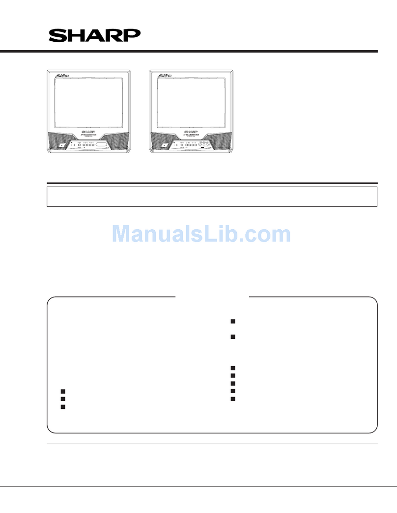
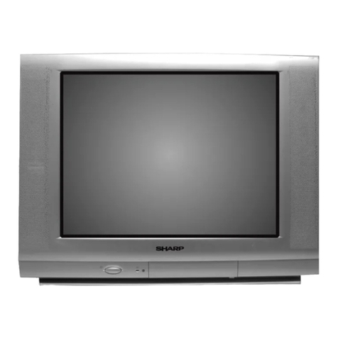
Sharp CX-34G3 User manual

_)
CX-34G3
CX-51 G3
SHARP
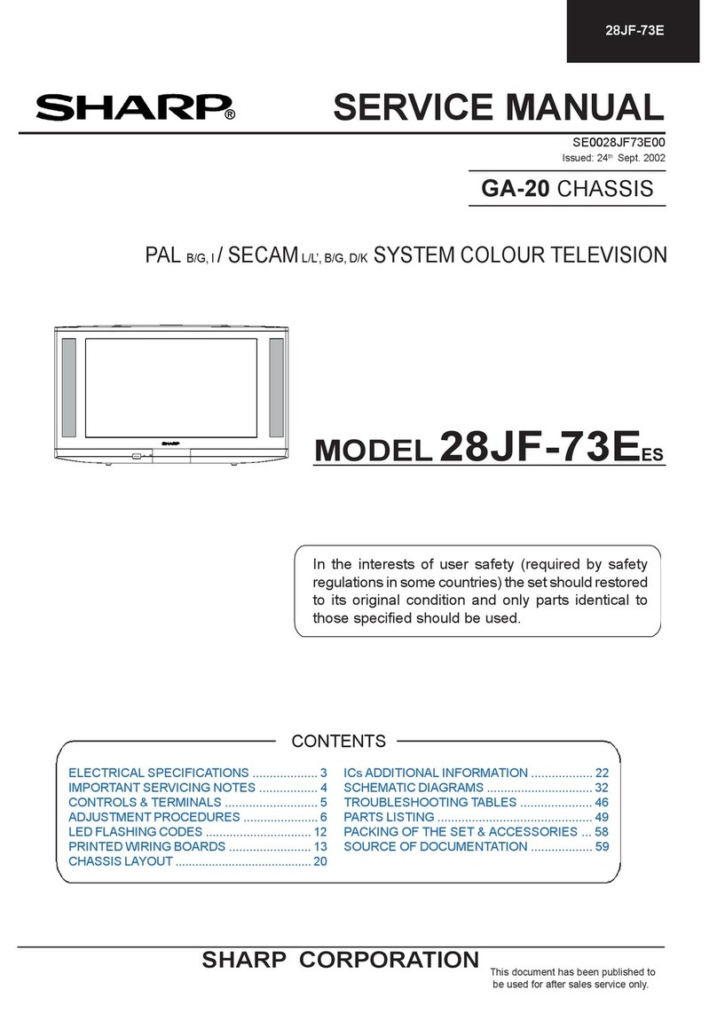
SERVICE MANUAL
SX7i2CX-51
G31
CX-34G3
CX-51
G3
COLOUR TELEVISION
Chassis No.
SP-67
CX-34G3
MODELS
CX-51
G3
In the interests of user-safety (Required by safety regulations in some countries) the set should
be
restored
to its original condition and only parts identical to those specified should be used.
FEATURE
n
Reminder/ON-Off Timer
n
Blue Back Noise Mute
n English/Arabic/Chinese/French/Russian/Malay six
n
PAUSECAM
Dual System
Language
OSD
n
NTSC 4.43/3.58 MHz
(AV
only)
wHyper Band
PLL
Tuner
n
Direct Access Remote Control
n
Wide Range Chopper Regulator System
n
NTSC Colour-Comb Filter
n
Front A/V Input Rear A/V Input/Output Terminal
n
Black Strech Circuit
CONTENTS
Y
Page Page
l
SPECIFICATIONS
. . . . . . . . . . . . . . . . . . . . . . . . . . . . . . . . . . . . . . . . . . . . . . .
2
l
WAVE FORMS
. . . . . . . . . . . . . . . . . ..*..............................
22
l
IMPORTANT SERVICE NOTES
. . . . . . . . . . . . . . . . . . . . . . . .
2
. DESCRIPTION OF SCHEMATIC DIAGRAM
. . . . . . .
24
l
ADJUSTMENT PRECAUTIONS
. . . . . . . . . . . . . . . . . . . . . . . .
3
. BLOCK DIAGRAM
. . . . . . . . . . . . . . . . . . . . . . . . . . . . . . . . . . . . . . . . . . . .
29
l
TROUBLE SHOOTING TABLE
. . . . . . . . . . . . . . . . . . . . . . . .
17
. PRINTED WIRING BOARD ASSEMBLIES
. . . . . .
33
l SOLID STATE DEVICE BASE DIAGRAM
. . . . . .*.
19
l
REPLACEMENT PARTS LIST
. . . . . . . . . . . ..*...........
35
l
CHASSIS LAYOUT
. . . . . . . . . . . . . . . . . . . . . . . . . . . . . . . . . . . . . . . . . . .
20
WARNING
The chassis in this receiver is partially hot. Use an isolation transformer between the line cord plug and power
receptacle, when servicing this chassis. To prevent electric shock, do not remove cover. No user -serviceable
parts inside. Refer servicing to qualified service personnel.
SHARP CORPORATION

SPECIFICATIONS
Convergence.
. . . . . . . . . . . . . . . . . . . . . . . . . . . . . . . . . . . . . . . . . . . . . . . . . . . . . . . . . . . . . . . . . . .
Focus Self Converging System
. . . . . . . . . . . . . . . . . . . . . . . . . . . . . . . . . . . . . . . . . . . . . . . . . . . . . . . . . . . . . . . .
Quadra-Potential Electrostatic
Sweep
Deflection . . . . . . . . . .
. . . . . . . . . . . . . . . . . . . . . . . . . . . . . . . . . . . . . . . . . . . . . . . . . . . . . . . . . . . . . . . . . . . . . . . . . . .
Intermediate Frequencies Magnetic
Picture
IF
Carrier . . . . . . . . . . . . . . . . . . . . . . . . . . . . . . . . . . . . . . . . . . . . . . . . . . . . . . . . . . . . . . . . . . . . . . . . . . . . . . . . .
38.9 MHz
Sound IF Carrier Frequency
6.5
MHz
. . . . . . . . . . . . . . . . . . . . . . . . . . . . . . . . . . . . . .
. .
.
. . . . . . . . . . . . . . . . . . . . . . . . . . . . . . . . . . . . . . . . . . . . . . . . . . .
32.4
MHz
6.0
MHz . . . .
.._......
. . . . . . . . . . . . . . . . . . . . . . . . . . . . . . . . . . . . . . . . . . . . . . . . . . . . . . . . . . . . . . . . . . . . . . . . . . . . . . .
32.9 MHz
5.5
MHz
. . . . . . . .
. . . . . . . . . . . . . . . . . . . . . . . . . . . . . . . . . . . . . . . . . . . . . . . . . . . . . . . . . . . . . . . . . . . . . . . . . . . . . . . . . . . .
33.4
MHz
Colour
Sub-Carrier Frequency
._ . . . . . . . . . . . . . . . . . . . . . . . . . . . . . . . . . . . . . . . . . . . . . . . . . . . . . . . .
34.47
MHz
Power
Input . . . . . . . . . . . . . . . . . . . . . . . . . . . . . . . . . . . . . . . . . . . . . . . . . . . . . . . . . . . . . . . . . . . . . . . .
1
i O-240V
AC 50/60 Hz
Power Consumption
. . . . . . . . . . . . . . . . . . . . . . . . . . . . . . . . . . . . . . . . . . . . . . . . . . . . . . . . . . . . . . . . . . . . . . . . . . . . . . . . . . . . . . .
65
W
Audio Power Output Rating . . .
.._.
..“.................~...................................,..........
3.0 w
(at Max.)
Speaker
Size
. . . . . . . . . . . . . . . . . . . . . . . . . . . . . . . . . . . . . . . . . . . . . . . . . . . . . . . . . . . . . . . . . . . . . . . . . . . . . . . . . . . . . . . . . . .
Voice Coil Impedance . . .
5cmx9cmlpc
. . . . . . . . . . . . . . . . . . . . . . . . . . . . . . . . . . . . . . . . . . . . . . . . . . . . . . . .
16 ohms at 400 Hz
Aerial tnput Impedance
VHF/UHF . . . . .
. . . . . . . . . . . . . . . . . . . . . . . . . . . . . . . . . . . . . . . . . . . . . . . . . . . . . . . . . . . . . . . . . . . . . . . .
75 ohm Unbalanced
Receiving System
. . . . . . . . . . . . . . . . . . . . . . . . . . . . . . . . . . . . . . . . . . . . . . . . . . . . . . . . . . . . . . . . . . . . . . . . . .
CCiR PAL
6,
G
NTSC
3.58i4.43
MHz
(AV
Input Only)
Tuner Ranges
l
VHF-Channels ....
.._.......................... E2
(48.25 MHz)
thru
El2
(224.25 MHz)
Cl (49.75 MHz)
thru
Cl2
(216.25 MHz)
Sl
(105.25 MHz)
thru
S41
(463.25 MHz)
l
UHF-Channels
. . . . . . . . . . . . . . . . . . . . . . . . . . . . .
E21
(471.25 MHz)
thru
E69
(855.25 MHz)
Cl3
(471.25MHz)
thru
C57
(863.25 MHz)
Dimensions
CX-34G3 . . .
.. . . . . . . . . . . . . . . . . . . . . . . . . . . . . . . . . . . . . . . . . . . . . . . . . . . . . . . . . . . . . . . . . . . . . . . .
Width:
357.0
mm
Height: 360.0 mm
Depth: 359.5 mm
CX-51G3
...
..I.......
Weight (approx.): 9.5 kg
. . . . . . . . . . . . . . . . . . . . . . . . . . . . . . . . . . . . . . . . . . . . . . . . . . . . . . . . . . . . . . . .
Width:
449.0
mm
Height: 475.0 mm
Depth: 473.0 mm
Cabinet Material . . . . . . . . . . . . . . .
Weight (approx.): 21.0 kg
... . . . . . . . . . . . . . . . . . . . . . . . . . . . . . . . . . . . . . . . . . . . . . . . . . . . . . . . . . . . . . . . . . .
All Plastics
Specifications are subject to change without
prior notice.
1
2-l
IMPORTANT SERVICE NOTES
Maintenance and repair of this receiver should be done by
qualified service personnel only.
SERVICING OF HIGH VOLTAGE SYSTEM AND
PICTURE TUBE
When servicing the high voltage system, remove static charge from it by
connecting a 10k ohm Resistor in series with an insulated wire (such as a
test probe) between picture tube dag and 2nd anode lead. (AC line cord
should be disconnected from AC outlet.)
1.
Picture tube in this receiver employs integral implosion protection.
2.
Replace wlth tube of the same type number for continued safety.
3.
Do not lift picture tube by the neck.
4.
Handle the picture tube only when wearing shatterproof goggles and after discharging
the high voltage completely
X-RAY
This receiver is designed so that any X-Ray radiation is kept to an absolute
minimum. Since certain malfunctions or servicing may produce potentially
hazardous radiation with prolonged exposure at close range, the following
precautions should be observed:
1.
CX-34G3:
When repairing the circuit, be sure not to Increase the high voltage to more
than 23.5
kV
(at beam 0
PA)
for the set.
CX-51G3:
When repairing the circuit, be sure not to Increase the high voltage to more
than 29.0
kV
(at beam 0
PA)
for the set.
2.
CX-34G3: To keep the set in a normal operation, be sure to make it function on 22.0 kV
f
1.5
kV
(at beam 800
PA)
in the case of the set. The set has been factory
-
Adjusted to the above-mentioned high voltage.
CX-51G3: To keep the set in a normal operation, be sure to make it function on 24.8 kV
f
1.5
kV
(at beam 1100
PA)
in the case of the set. The set has been factory
-
Adjusted to the above-mentioned high voltage.
:.
If there is a possibility that the high voltage fluctuates as a result of the repairs, never
forget to check for such high voltage after the work.
3.
Do not substitute a picture tube with unauthorized types and/or brands which may cause
excess X-ray radiation.
BEFORE RETURNING THE RECEIVER
Before returning the receiver to the user, perform the following safety
checks.
1.
Inspect all lead dress to make certain that leads are not pinched or that hardware is not
lodged between the chassis and other metal parts in the receiver.
2.
Inspect all protective devices such as non-metallic control knobs, Insulating fishpapers,
cabinet backs, adjustment and compartment covers or shields, isolation resistor-
capacity networks, mechanical Insulators etc.
2-2
ADJUSTMENT PRECAUTIONS
n SERVICE MODE
This model’s settings are adjusted in two different ways: through the
PC
bus control and in the conventional analog
manner. The adjustment via the
PC
bus control includes preset-only items and variable data.
1. Calling the service mode by the microprocessor
@
Set the switch S1006 to the service mode position, and the microprocessor is put in the service mode
(adjustment through the
PC
bus control).
@Press the
CH
UP/DOWN keys on the remote controller to select the modes one by one.
@
Press the CH UP/DOWN keys on the remote controller to select the modes in the order opposite to the
above step
0.
@
Using the VOLUME UP/DOWN keys on the remote controller, the data can be modified.
@Set the switch
S1006
to the normal mode (OFF) position, and the microprocessor is put out of the
service mode.
2. Factory presettings
@
Set the switch S1006 to the service mode position and turn on the main power switch. Initial values are
automatically preset only when a new
E2PROM
is used (judgment with the first 4 bytes).
@
The initial data are preset as listed on pages 4 and 5.
@
Keep in mind that some settings should be modified, and the others should remain as preset.
Once the chassis has been put together, be sure to set the switch S1006 to the service mode position
first and then turn on the main power switch (see the step
2.-@
above). Turning on the power without
initializing the E*PROM may cause a flow of excess beam current.
c4.3
3. The accompanying memory map (12-page document for the RH-iX2938CE) is for your
reference.
3-1
(1) Press the specific keys to change the modes as follows.
COLOUR ADJUST mode
60 Hz ADJUST mode
In the direction of arrow :
CH
DOWN key
In the opposite direction :
CH
UP key
{
CUT-OFF/BKGD
mode
R-CUT OFF
G-CUT OFF
B-CUT OFF
4
,
b
4
HORIZONTAL mode
3-set
time out
3-set time out
KEY
R-CUT OFF
G-CUT OFF
B-CUT OFF
R-DRIVE
B-DRIVE
HORIZONTAL mode
UP DOWN
1
KEY
4
KEY
2
KEY
5
KEY
3
KEY 6KEY
7 KEY
F/B
KEY
8
KEY
0
KEY
9 KEY
COLOUR ADJUST mode
4
V-AMP 50 Hz
(V-AMPSO)
4
V-LINE 50 Hz
(V-LINE50)
4
S-CORRECT 50 Hz (V
S-CORRSO)
4
V-PHASE 50 Hz
(V-CENTER50)
4
H-PHASE 50 Hz (H-CENTER50)
4
V-BLK
START
(V-BLK
ST50)
4
V-BLK
STOP
(V-BLK
SP50)
4
SECAM
R-Y (R-Y)
4
SECAM
B-Y (R-Y)
In the direction of arrow :
CH
DOWN key
In the direction of arrow :
CH
DOWN key
In the opposite direction : CH UP key
In the opposite direction :
CH
UP key
l
The characters in parentheses appear on the on-screen display.
3-2

SUB
CONT+ST
(SUB CON)
SUB BRIGHi (SUB
BRI)
SUB COLO”p (SUB
COL)
SUB
SUBTIY
( SUB TIN)
SUB SHAFtTESS (SUB SHARP)
Y-SUB CONTRAST (Y SUB CON)
4
V-AMP 60
Hi
(V-AMPGO)
V-LINE 60
H;
(V-LINEGO)
VS-CORRECT
60 Hz
4
V-PHASE 60 Hz
(V-CENTERGO)
4
H-PHASE 60 Hz
(H-CENTERGO)
4
V-BLK
STABT
60 Hz
(V-BLK
ST60)
t
4
Y DELAY
PA/-
(DT
PAL
TV/AV)
Y DELAY
SECAM
(DT
SECAM
TV/AV)
4
Y DELAY N;SC
(DT
NTSC
TVIAV)
Y DELAY
BtW
(DT
BW
TVIAV)
4
VIDEO
MUT;
ON/OFF (V-MUTE)
VIDEO 2 ON/OFF
(AV2)
(DELAY AN effective in AN mode)
V-BLK
STOP 60 Hz
(V-BLK
SP60)
In the direction of arrow :
CH
DOWN key In the direction of arrow
In the opposite direction :
CH
UP key
: CH DOWN key
In the opposite direction :
CH
UP key
l
The characters in parentheses
appear on the on-screen display.
l
When the modes are switched, the last service mode data are stored into the
E2PROM.
l
In the service mode, the user data are preset as follows.
CONTRAST
COLOUR
BRIGHTNESS
TINT
SHARPNESS
S-VOLUME
BLUE BACK
C SYSTEM
S SYSTEM
User data
MAX (64164)
CENT
(32/64)
CENT (32/64)
CENT
(32/64)
CENT (32/64)
MIN
(l/64)
OFF
AUTO
*
‘1
l
The following keys are used to go directly to their respective modes,
‘1 :
Settings of each
before switching
mode.
VIDEO MUTE
I
BLUE BACK
channel
to the service
l
To go to the service mode, the data at the E2PROM’s addresses
OOH
thru 03H are read. If the data are not as
given below, the
E2PROM
is initialized according to the table below.
Address : Data
OOH
:
22H 02H
:
13H
I
(OOH)
OlH
:
29H 03H
:
48H
E’PROM item IData adjustable range) Data initial value
1
Remarks
II
3c)L-l
I
(OlH)
W’f-4
(03H)
R
CUT OFF
G CUT OFF
B CUT OFF
G DRIVE
B DRIVE
50Hz V-AMP
50Hz V-LINEARITY
50Hz S-CORRECTION
50Hz V-PHASE
50Hz H-PHASE
V-BLK
ST
50
V-BLK SP
50
60Hz V-AMP
CL,
I
29H
13H
48H
0
-
255
0
0
-
255 0
0
-
255 0
0
-
255
127
0
-
255 127
0
-
127 58
1
‘1
o-
31
16
-2
l 1
0
-
127 50 (14”)/67 (21”) 7‘1
‘2
0
-
7
r;
-3
-.
l
1
o- 31
;
+5
l 1
0-
63
58-+63
(50Hz)
0 .
127
25
n
137
60Hz V-LINEARITY
60Hz S-CORRECTION
60Hz V-PHASE
60Hz H-PHASE
60Hz
V
BLK
ST
60Hz
V
BLK
SP
SECAM
R-Y
SECAM
B-Y
SUB-CONTRAST
SUB-BRIGHT
SUB-COLOUR
SUB-TINT
SUB-SHARPNESS
Y SUB-CONTRAST
DT
PAL TVIAV
DT
SECAM
TVIAV
DT
NTSC
TV/AV
DT
BiW
TVIAV
V-MUTE
AN2
AFT/SKIP
C-SYSTEM
S-SYSTEM
v-
IL,
o- 31
0
-
127
l
2
0
-
7
‘4
o-
31
O-
63 60-+63
(60Hz)
0
-
127
20
o-
15
10
o-
15
6
0
-
255 255
‘2
0
-
255
127
0
-
255
110
0
-
127 70
0-
63 28
o-
31 18
l
2
0
-
7
2l2
‘2
0
I
7
414
‘2
0
-
7
2f2
‘2
0
-
72l2
‘2
ON/OFF OFF
ON/OFF ON
0
-
1
OFF/ON
PIG
II
YIU
NVM
I
With all the adjustments complete, do not change the data of addresses
OOH
thru 03H. Other-
‘3
wise the E*PROM will be initialized when the AC power is turned on.
l 1 : These data are additionally adjusted for 60Hz based on the 50Hz settings.
‘2 : Unless otherwise specified, these data are fixed and need no adjustment.
4-2

l
3 : When the
ICI001
is
RH-iX2938CEZZ/Nl,
change the NVM data from 00 to 01 (address
198H). For the
RHiX2938CEN2
and the following
ICs,
there is no need to change this data
(as from the July 1997 production).
‘4 : Only 0 through 5 must be used in changing the data.
INITIAL SETTINGS OF CHANNEL SELECTION DATA
(1) Make an entry of MCLI in the service mode in order to set the following channel selection data to the
E2PROM.
And select the POSl channel. (An
MCL2,
-3 or -4 input makes different settings.)
FACTORY SETTING
(1) The following key-in data have been factory-set for the
E2PROM.
LAST
FB
POS
1
VOLUME MIN
CONTRAST MAX
COLOUR CENT
BRIGHTNESS CENT
TINT CENT
SHARPNESS CENT
*I
: For settings, refer to the Job Instruction Sheet.
5-1
5-2

115V
ADJUSTMENT
Adjusting point Adjusting procedure/conditions Waveform and others
115v
1. Receive the E-5CH (monoscope pattern) signal.
adjustment:
2. Using the remote controller, call the P-NORM
R71l
mode.
3. Connect a beam ammeter between
TP602
and
TP603.
0
Ammeter’s full-scale
: 3 mA range
l Ammeter’s positive
(+)
lead :
TP603
l
Ammeter’s negative (-) lead : TP602
4. Take the beam ammeter reading to make sure
that the beam current is between 600 pA and
800
uA
(14”)/900 pA and 1100 pA (21”).
l If not, readjust the
FBT
screen control to ob-
tain the beam current of 600-800 uA (14”)/
900-1100 pA (21”).
5. Connect a digital voltmeter to TP701.
6. Adjust
R711
so that the digital voltmeter should
read 115
kO.5
V.
PIF CHECKING
Jo. Adjusting point
Adjusting procedure/conditions Waveform and others
1 Tuner IF 1. Get the tuner ready to receive the
E-9CH
signal.
(preset):
but with no signal input. Adjust the PLL data. IF-OUT
TU201
2. Connect the sweep generator’s output cable to
1
ooop
1
Okf;!
the tuner antenna. (RF sweep)
3. Adjust the sweep generator’s output level to 80
dBj.rV.
4. Connect the response lead (use a low-impedance
probe with wave detector; see Fig.
7)
to the
tun-
er’s
IF output terminal.
(This terminal must have the probe alone con-
nected.)
5. Set the RF
AGC
voltage to
O-6
V with no contact
with the waveform.
7s$gfjffjfOPf
Fig.
7
E-9CH
6. Adjust the tuner IF coil to obtain the waveform as
shown in
Fig. 2.
Note: Be sure to keep the tuner cover in posi-
u
P
tion during this adjustment.
-
1.5dB
+
0.8dB
Fig. 2
6-1
PIF/AFT/AGC ADJUSTMENT
lo. Adjusting point
Adjusting procedure/conditions Waveform and others
1
VCO
adjust-
1. Disconnect the antenna from the tuner antenna
l
Warm up the unit for longer than
ment:
T203
terminal. 10 minutes in advance.
2. Apply DC voltage to pin
(4)(IF
AGC)
of
IC201.
l
DC voltage: 6.0 V (allowable +O.l V)
3. Using a digital voltmeter, measure the DC volt-
age at pin
(2O)(PLL
FIL)
of
IC201.
l The digital voltmeter must be able to take read-
*
10 kHz at about 0.007 V.
ings
down to the third decimal place.
4. Relieve pin (4) of
lC201
of the DC voltage.
5. Reconnect the antenna in position and receive l Position the
T203
core in the
the E-12CH signal. (With the AFT off, adjust the
range in which the E-l
2CH
sig-
receiving frequency to 224.25 MHz.) nal
can be received.
6. Connect the DC digital voltmeter to pin (20) of
IC201.
Adjust
T203
so that the voltmeter should
read the same voltage as in Step 3.
Allowable error : 0.015 V (20
kHz)
2 AFT
adjustment:
T204
3 RFAGC
cut-in
adjustment:
R216
1. Receive the
E-12CH
(PAL
colour
bar) signal. If
this signal is not available, any signal above the
E-5CH band is acceptable.
l
Field strength : 55-80 dBpV
DC voltage at
TP201
6V
Make sure the frequency is almost the same as
that of the received channel
(i30
kHz).
3.3v
-
-
-
,
2. Using the channel setting control, make a
fre-
I
quency of 224.25 MHz appear on the screen (the
I
AFT turns off). If any other channel than E-12CH
bL
DOWN A B’
;
B”
C UP
is received, make its frequency on the screen.
(The AFT turns off when the on-screen display
Fig. 3
turns yellow.)
l Turn the core
counterclockwise
3. Turn
T204
clockwise to have a
6V
point, and for the UP direction, and clock
counterclockwise to have a 0.2-V point. Position wise for the DOWN direction.
the coil at the center of these two points.
Adjust the
T201
core to point E
4. Adjust
T204
so that the DC voltage at pin (1) (AFT
(between
B’
and
B”).
(Points
F
OUT terminal) of
IC201
be 3.3
kO.1
V(See
Fig.
3)
and C are rejectable.)
1.
Receive the
E-12CH
(PAL
colour
bar) signal. Note: If a 500hm field
strength
l
Field strength : 57
k.1
dBpV (75 ohms open)
meter is used without a
50/X
2. Connect the oscilloscope to TP210, as shown in
impedance converter, set
thf
Fig. 4.
field strength to 55
*l
dBpV
Oscilloscope TV Set
Pay attention to a loss
tha
would be caused with the con
m-l-v +
TP210
. . . . . .
SF
verter.
Bias box
+
Fig.
4
l
Bias box: About 6.5 V
3. Turn R216 to have the highest voltage.
4. Turn R216 slowly in the opposite direction until the
voltage goes down 0.1 V below the highest level.
5. Adjust thesignal level to 63-67 dBpV and make
sure there is no noise.
6. Now adjust the signal level to 90-95
dBuV
and make
sure there is no chrominance modulation beat.
6-2

PURITY ADJUSTMENT CONVERGENCE ADJUSTMENT
rlo.
j
Adiustins
point
j
Adiusting procedure/conditions
I
Waveform and others
Purity
adjustment
1. Using the remote controller, make the screen
colour
green-only. Adjust the contrast control to have a beam
current of about 500
f.tA
(14”)/700 pA (21”).
2.
Degauss
the cathode ray tube enough with the
degaussing coil.
Note: Follow the Job Instruction Sheet to ad-
just the magnetic field.
Vertical
Bv
: +0.030 mT (0.30 gauss)
Horizontal
Bh
: +0.020 mT (0.20 gauss)
See page 10.
3. Keep the purity magnet in the zero magnetic field
in advance. Roughly adjust the convergence.
4. Observe the points “a” and “b”, as shown in
Fig.
5-1, through a microscope. Adjust the landing to
the rank “A” requirements.
5. Adjust the raster rotation to
“0”
eastward.
6. Tighten up the deflection coil.screws.
l
Tightening torque: 108
*20
N (11 lt2
kgf)
7. While observing the cathode ray tube corners.
apply the magnet sheet to have the landing at
rank “A”.
Note: Before starting this adjustment, warm
up the unit for 30 minutes or longer at
a beam current of over 500
f.rA
(14”)/
700 pA (21
I’).
Note: Set the service switch SlOOl to call the
service mode and press the
single-col-
our key on the process remote control-
ler to get the green-only screen.
l
Each time
the
single-colour key is pressed, the
screen
colour
changes as follows.
Fig.
5-l
Fig. 5-2
Rank “A” (on the
right of the CRT)
Green-only Blue-only Red-only
screen screen screen
T
Single-colour
Fig. 5-3
screen cleared
Rank “A” (on the
left of the CRT)
l
Whether in the service mode
OI
not, hold down the single-coloul
key for 1 second or longer
ant
the service mode is called.
The TEXT key or the R.G.Cy kel
may be used instead to
provide
the single-colour screens.
o.
j
Adiustina
j
Adiuztino
oracedurelconditions
I
Waveform and others
1. Receive the E-2CH (crosshatch pattern) signal.
I
2. Using the remote controller, call the Normal mode.
STATIC CONVERGENCE
1. Turn the
4-pole
magnet to a proper opening an-
gle in order to superimpose the blue and red col-
ours.
2. Turn the
g-pole
magnet to a proper opening an-
gle in order to superimpose the green colour over
the blue and red colours.
DYNAMIC CONVERGENCE
1. Adjust the convergence on the fringes of the
screen in the following steps.
a) Fig.
6-7:
Drive the wedge at point “a” and
swing the deflection coil upward.
b) Fig.
6-2:
Drive the wedges at points
‘lb”
and
“c”
and swing the deflection coil downward.
c) Fig.
6-3:
Drive the
“c”
wedge deeper and
swing the deflection coil rightward.
d) Fig. 6-4: Drive the
“b”
wedge deeper and
swing the deflection coil leftward.
2. Fix all the wedges on the cathode ray tube and
apply glass tape over them.
3. Apply lacquer to the deflection yoke lock screw,
magnet unit (purity, 4-pole and 6-pole magnets),
and magnet unit lock screw.
Finally receive the red-only and blue-only signals
and make sure there is no other colour mixed on
the screen.
BGR
Fig.
6-i
RGB
I\
:
I
:
\
:
‘.
. . . . . . .
.
-
_---
_--- “-
/
. . . . . .
4
:
\
. . . . .
:
\
B
:
\
:
\
Fig. 6-2
Fig. 6-3
Fig. 6-4
Wedge “a”
Fig. 6-5
Purity magnet
fig. 6-6
7-2

CRT CUT-OFF, BACKGROUND AND SUB-CONTRAST ADJUSTMENT
00
So. Adjusting point Adjusting procedure/conditions Waveform and others
1
CRT cut-off
1. Receive the E-5CH (monoscope pattern) signal.
l First of all, make sure that the
service mode:
2. Using the remote controller, call up the P-NORM R/G/B cut-off and B/G drive data
12C
bus data
mode. are all initial values.
adjustment
3. Turn on the service switch and select the cut-off/
background mode.
Note:
4. Set the screen control to
O/10
position.
R
CUT OFF UP
“1” KEY
5. Press the
“9”
key on the remote controller to reach
DOWN “4” KEY
the horizontal centering mode.
G CUT OFF UP “2” KEY
6. Turn the screen control clockwise until the
hori-
DOWN “5” KEY
zontal
raster of the first glimmering
colour
be-
6
CUT OFF UP
“3”
KEY
comes slightly visible.
DOWN “6” KEY
7. Adjust the cut-off data of the other two
colours
until the horizontal raster becomes whitish.
The data can be turned up and
8. Turn the screen control counterclockwise until the
down with the above keys.
horizontal raster disappears.
(Continued)
lo. Adjusting point
Adjusting procedure/conditions
Waveform and others
2
White balance
1. Receive the E-5CH (monoscope pattern) signal.
See page 5.
and
2. Using the remote controller, call up the Video l 12300°K X: 0.273
background
Normal mode.
Y
: 0.276
service mode:
3. Connect the beam ammeter between
TP601
and
1%
bus data
TP602.
(with colour temperature meter
adjustment
4. Make sure the beam current is about 800
PA
CA-100
(MINOLTA).)
(14”)/1,100
PA
(21”).
9. Press the
“9”
key on the remote controller to call
II
12345
the NORMAL mode.
Note: Before starting this adjustment, warm
up the unit for 30 minutes or longer at
a beam current of over 500
PA
(14”)/
700
PA
(21”).
5. Adjust the G-drive and B-drive data to have a
Note:
colour
temperature of
12,300”K
(white). G-DRIVE UP
“7” KEY
6. Adjust the contrast and brightness controls to DOWN
“-I--”
KEY
have the beam current of 200
PA.
Now check the
B-DRIVE UP
“8” KEY
background
colour.
If the
colour
temperature is DOWN
“0”
KEY
not as specified, go back to No. 1 on the preced-
ing page.
The data can be turned up and
Note: Before starting this adjustment, warm down with the above keys.
up the unit for 30 minutes or longer at a
beam current of over 500 pA (14”)/
700
pA
(21”).
iO.Using
the remote controller, call the
sub-bright-
ness
setting mode. (Receive the
E-2CH
signal.)
11. Set the sub-brightness data so that the third black
portion
(1st
to
5th
counted from the left of the
screen) of the window pattern looks sinking.
Note: The service mode adjustment in the
above steps 10. and 11. should be car-
ried out after the white balance and
background adjustments.
Make sure all the Ist,
2nd
and
3rd
black portions are at the
same black level.
3 Maximum
1. Receive the E-5CH (monoscope pattern) signal.
beam current
2. Using the remote controller, call up the Video
(check item)
Normal mode.
3. Connect the beam ammeter between TP602 and
TP603.
l
Ammeter’s full-scale
: 3
mA
range
l
Ammeter’s positive (+) lead : TP603
l
Ammeter’s negative (-) lead : TP602
4. Make sure the beam current is 800 *lOO
PA
(14’11
1,100*100pA
(21”).
Note: Before starting this adjustment, warm
up the unit for 30 minutes or longer at
a beam current of over 500
PA
(14”)/
700
PA
(21”).
8-1
8-2
CRT CUT-OFF, BACKGROUND AND SUB-CONTRAST ADJUSTMENT

HORIZONTAL AND VERTICAL CIRCUIT ADJUSTMENT PAL CHROMA ADJUSTMENT
lo.
1
Adlustina
ooint
1
Adiustina
orocedurekonditions
I
Waveform and others
V-AMP 50
V-LINEARITY
-
50 Hz
V-S CORREC-
TION
-
50 Hz
V-SHIFT 50
(V-
1. Align the screen center with the cathode ray tube’s
CENTER)
geometrical center (E-5).
H-SHIFT (50)
1. Align the screen center with the cathode ray tube’s
(H-CENTER)
geometrical center (E-5).
1. Adjust the
overscan
to 9%
(E-5).
1. Adjust to get the best linearity.
1. Preset (readjust if the linearity is poor).
Note: For the V-HEIGHT 60, V-LINEARITY 60,
V-S CORRECTION 60, V-SHIFT 60 and
H-SHIFT 60 adjustments, their corrected
data are automatically entered when the
corresponding 50
Hz
mode adjustments
are made.
The selected channels in paren-
theses have the following signals.
(E-2):
Crosshatch pattern (50 Hz)
signal
(E-5):
Monoscope pattern (50 Hz)
signal
Receive the
E-5CH
(monoscope pattern) signal.
Using the remote controller, call the Video Nor-
mal mode.
Adjust the focus control so that the screen be in
good focus.
9-1
o. Adjusting point
Adjusting procedure/conditions Waveform and others
1
Sub-colour
1. Receive the E-l 2CH (PAL colour bar) signal.
adjustment:
2. Using the remote controller, call the Video
Nor-
12C
bus
mal
mode.
B
adjustment
3. Connect the oscilloscope to
TP851
(14”)1TP852
(21”) (RED cathode). (Use a 10 : 1 probe.)
l
Range
: 2 Vldiv.
l
Sweep time : 20 usecldiv.
4. Using the remote controller, call the
sub-colour
w
adjustment mode. Adjust the sub-colour data so
W Y
lOO%WMg
R
that the 75% white and red portions of the PAL
colour bar be at the same level. See Fig. 7.
Fig. 7
5. Clear the adjustment mode. (Now the 100% white
and red portions will be at the same level. The
sub-colour data is up 20.)
l Pin
(3)(K)
may be used instead of
TP851
(14”)/
TP852
(21”) (RED cathode) for this adjustment.
In such case, keep in mind that the polarity of the
waveform is inverted.
NTSC
CHROMA
ADJUSTMENT
lo. Adjusting point
Adjusting procedure/conditions Waveform and others
1 Sub-tint 1. Call the sub-tint adjustment mode. Receive the
adjustment:
NTSC 3.58 colour bar signal in the A/V mode.
(B-Y)
12C
bus
2. Connect the oscilloscope to pin (36)(B-Y) of A
4
adjustment
IC801.
l
Range
: 20 mV/div. (AC)
B4
l
Sweep time : 20 psec/div. (Use a 10 : 1 probe.)
c
c-
-
-
-
-
-
-
-
-
-
-
-
3. Adjust the sub-tint data to obtain the waveform
as shown in
Fig. 8.
@
4. Clear the adjustment mode.
WYCyGMgRB
Fig. 8
A=B=C
9-2

SECAM
CHROMA
ADJUSTMENT
lo. Adjusting point
Adjusting procedure/conditions Waveform and others
1 SECAM black
1.
Receive the
Oi-5CH
(SECAM
colour
bar) signal.
level (R-Y/B-Y)
2. Call the SECAM black level adjustment R-Y mode.
adjustment:
3. Connect the oscilloscope to pin
(34)(R-Y
OUT,
1%
bus
TP802)
of
IC801.
adjustment
l
Range
: 10
mV/div.
-- +
_
_-_-_
e-v-
-e---v
l
Sweep time : 20 psec/div. (Use a 10 : 1 probe.)
4. Adjust the R-Y data so that the offset between
1”-
OFF SET
the no-signal line and the signal line be minimum.
See Fig. 9-l(b).
5. Call the SECAM black level adjustment B-Y mode.
6. Reconnect the oscilloscope to pin (33)(B-Y OUT,
TP801) of IC801. The conditions are just the same
as in Step 3.
Fig.
9-l
(a)
4
7. Adjust the B-Y data so that the offset between
the no-signal line and the signal line be minimum.
--
7-F
_-
-_-_
_-_-_
_
_-_
See Fig.
9-2(b).
Fig.
9-l
(b)
!111
__
_-
-_
_
-- -_
_-_
OFF
S:;
Fig. 9-2 (a)
+
@
-- -- -_
_
-- -_
__
Fig. 9-2 (b)
10-l
e
4
iY
PROTECTOR PERFORMANCE CHECK
lo. Adjusting point
Adjusting procedure/conditions Waveform and others
1 Beam
protec-
1. Receive the
EdCH
(monoscope pattern) signal.
l Short-circuit any of the
Q851
tor
2. Set the contrast control to maximum.
0852 and 0853.
3. Set the brightness control to maximum.
4. Make a short-circuit between the collector and
emitter of
Q851,
Q852
or
Cl853
and make sure
that the protector is activated and the stand-by
mode is called.
2 High-voltage
protector
1. Receive the
E8CH
(monoscope pattern) signal.
2. Connect the bias box to the cathode (R635 side)
of
D607.
3. Adjust the bias box voltage to 18 V and make
sure that the protector is not activated.
4. Adjust the bias box voltage to 27 V and make
sure that the protector is not activated.
3 Other
protec-
1. In checking the performance of other protectors
tors
-
for example, the one against shorting of
smoothing electrolytic capacitor of
+B
line
-,
pay
attention not to damage or deteriorate any related
element.
A/v
INPUT AND OUTPUT CHECK
lo. Adjusting point
Adjusting procedure/conditions Waveform and others
1 Video and
1. Receive the E-12CH colour bar (100% white col-
audio output
our bar, 400 Hz, 100% modulation audio) signal.
check
2. Terminate the video output with a 75 ohm imped-
ance. Make sure the output is as specified
(1
.O
Vp-p
*3
dB).
3. Terminate the audio output with a
10k
ohm im-
pedance. Make sure the output is as specified
(1.76
Vp-p
rt3
dB).
2 Video and
audio input
check
1. Using the
TV/AV
key on the remote controller,
make sure that the modes change in the order of
TV,
AV1,
AV2
and TV again and that the video
and audio outputs are according to the input and
output terminals for each mode.
10-2

FUNCTION CHECK (VIDEO AND AUDIO) FUNCTION CHECK (VIDEO AND AUDIO) (Continued)
lo. IAdiustina uointl Adiustina
wocedure/conditions Waveform and others
e
-.
-
-.
1
CONTRAST
1. Receive the E-5CH signal.
key
2. Select the contrast on the P-MODE screen.
3. The contrast must be changeable with the UP/
DOWN key.
2 COLOUR key
I.
Receive the
E-12CH
signal.
2. Select the colour on the P-MODE screen.
3. The colour must be changeable with the UP/
DOWN key.
3
BRIGHTNESS
I.
Receive the
E-5CH
signal.
key
2. Select the brightness on the P-MODE screen.
3. The black level must be changeable with the UP/
DOWN key.
4 TINT key
1. Receive the NTSC colour bar signal. (A/V)
2. Select the tint on the P-MODE screen.
3. The tint must be changeable toward green with
the UP key and toward red with the DOWN key.
5
PIC-NOR.
key 1. Press the NOR. key on the P-MODE screen to
l
The contrast,
colour,
brightness,
make sure all the displayed items are at normal
tint and sharpness settings are
settings. all normal when these items
dc
See below for the normal settings. not appear on the screen.
l
Contrast
: MAX
l
Colour : CENTER
l
Brightness : CENTER
l
Tint
: CENTER
l
Sharpness : CENTER
6 SHARPNESS
1. Receive the E-5CH signal.
key
2. Select the sharpness on the P-MODE screen.
3. The sharpness must be changeable with the UP/
DOWN key.
7 Channel sign
1. The display colour of all the channel
(O-99)
signs
display
coiour
must be green. Keep the AFT on.
11-1
o. Adjusting point
Adjusting procedure/conditions
Waveform and others
9
COLOUR 1. Receive the E-l
2CH
PAL
colour
bar signal.
Us-
SYSTEM key
ing
the COLOUR SYSTEM key, select a mode
other than PAL and make sure the colour system
does not work properly.
2. Receive the
E-37CH
NTSC
4.43
colour
bar sig-
nal. Using the COLOUR SYSTEM key, select a
mode other than N4.43 and make sure the colour
system does not work properly.
3. Receive the
NTSC
3.58
colour
bar
(A/V)
signal.
Using the COLOUR SYSTEM key, select a mode
other than
N3.58
and make sure the
colour
sys-
tem does not work properly.
9 SOUND I. Receive the
01-9CH
PAL
colour
bar signal.
Us-
SYSTEM key
ing
the SOUND SYSTEM key, select B/G and I
modes and make sure the sound system does
not work properly.
2. Receive the
E-23CH
monoscope pattern signal.
Using the SOUND SYSTEM key, select B/G and
D/K modes and make sure the sound system does
not work properly.
3. Receive the E-12CH colour bar signal. Using the
SOUND SYSTEM key, select I and D/K modes
and make sure the sound system does not work
properly.
IO Noise mute
check
1. Receive the E-12CH (PAL colour bar) signal.
2. Turn up the sound volume to maximum and make
sure the sound is heard normally from the speak-
ers. Then cut off the signal.
3. Make sure the sound muting functions.
4. Finally turn down the sound volume to minimum.
11-2

MEMORY MAP
(RH-iX2938)
,
SUB
DATA FACTORY
DDRESS
7
1
6
1
5
1
4
1
1
CRlTERlA
R
1
7
1
1
n
REMARKS
I
I
SElTlNG
I
I
I 003 I
-
-
-
-
I
II
initialization judgment data “22” Other than $22
$22
Initialization judgment data “29” Other than $29 $29
Initialization
iudament
data
“13’ Other than $13 $13
*
-
Initialization
iudament
data
“48”
I
c
)thnr
than
$48
$48
I
I
004
I
I
t
ii&
I
006
1
I
007 I
I
008 I
*
”
PLL
data
(uooerl
-~-
-\rr
I
PLL data (lower)
PLL
data
(L.
wper)
PLL
data (lowerj
PLL
data iurx)e;I
. .
.-.
.
.-.
_
.-
-
-
I
CHO
I
CHl
CH2
012
1
013 I
PLL
data (i
PLL
data
(lower)
t OIA
1
I
1
fl1B
1
017
018
019
.I,
I
PLL data (lower)
PLL
PLL
data
iI
data (upper)
ower)
PLL
data (upper)
PLL
data
il&eri
1
I I
I
CHIO
CHll
II
I
OlC
OlD
OlE
1
OlF
1
I
I 020 I
\
PLL
data
(uppe;)
PLL
data
(lower)
PLL
data (I
Jeer)
PLL
data (lowerj
PLL
data
&De;)
CH12
CH13
CH14
021
022
023
024
1
025
1
PLL
data ildwerj
PLL
data (upper)
PLL
data (lower)
PLL
data (upper)
CH15
CH16
026
1
027
1
PLL
data
ilower)
PLL
data iupper)
PLL
data
(lower) CH17
I
t
028
I
029
02A
028
1
02c I
PLL
data
iuDDe;I
-..
,
PLL data (lower)
PLL
data (upper)
PLL data (lower)
PLL
data (upper)
I
CH18
I
CH19
CH20
t
02D
i
PLL
data
ildwer)
t
I
02E
1
PLL
data
iucx)e;)
I
I
02F
1
. . . ,
PLL
data (lower)
12-1

FACTORY
SETTING
131211JU
ata
(upper) CH70
ata
(lower)
ata
(upper)
CH71
SUB
DATA
ADDRESS
’
-
’
-
’
*
’
n
7
1
6
1
6
1
4
090 PLL
dz
091
PLL
dz
092 PLL
di
093 PLL
dista
(lower)
094 PLL
di
ata
(upper)
095 PLL
di
ata
(lower)
096 PLL
ds
ata
(upper)
097 PLL
ds
ata (lower)
098 PLL
d
ata (upper)
PLL
d
I
1
CH72
CH73
I
CH74
lzF=
09B
09c
09D
09E
09F
OAO
OAl
OA2
OA3
OA4
OA5
OA6
OA7
OA8
OA9
OAA
OAD
1
OAE
I
PLL
d
PLL
d
PLL d
PLL d
lata
(lower)
PLL d
lata
(upper)
PLL d
lata
(lower)
PLL clata (upper)
PLL clata (lower)
PLL clata (upper)
PLL ctata (lower)
PLL
c-.-
\-TT
-
,
late
Imnerb
PLL data (lower)
PLL data (upper)
pLL
+dP
/ln!Amr\
PLL
(
PLL
(
PLL
L,.-
\-TT- ,
PLL data (lower)
PLL data (upper)
PLL data (lower)
PLL
data
(upper)
I
CH77
I
CH78
I
1
CH79
I
1
CH80
CH8
CH84
CH85
13-2
:ACTORY
SElTlNG

I SUB I
DATA
I
I
.
~-
ADDRESS
7
1
6
1
5
1
4
1
j
I
110
2
REMARKS
oco
OCI
PLL data (upper) CH94
PLL
data
Ilower\
bC2
oc3
oc4
oc5
t
--.-‘I
PLL data (upper)
PLL data (lower)
PLL data (upper)
PLL
data
(lower1
CH95
CH96
1
SUB
I
DATA
I
FACTORY
SETTING
CRITERIA FACTORY
SETTING
00
ADDRESS
76543
2
OF0 CH7
CH5
CH5
CH4
CH3
C&’
CHl
CHO
OF1
CHI
’
REMARKS CRITERIA
SKIP
0:OFF
1
:ON
SKIP ON
80
55
--3iT-
01
---F---
---r---
--iF---
--iF---
---T--
----E--
--E--
OC6
1
oc7
I
oca
oc9
OCA
OCB
PLL data (upper)
PCL
data
(lower1
. ,
\
-.--.I
PLL
data (upper)
PLL data (lower)
PLL data (upper)
PLL data (lower)
I
1
CH97
-.
.-,
I
CH98
CH99
OCC
POWER/
I
L
OCD
TVIAV
I’
’
II
OCE
BLUE BACKGROUND
1
One-digit/two-digit
1
OFFI .
LANGUAGE
I
1
Factorv-set
at ON
1
OCF
I
II
1
AST
POSITION
I
I
000
-,
LAST
CONTRkT
ODl
LAST COLOUR
OD2
LAST BRIGHTNESS
OD3
LAST TINT
II
OFE
1
III
I
I
t
II
I
OFF
1
I
I I I I
I
004
1
LAST SHARPNESS
I
I
I
m5
I
AST
VOLlJMF
I
“Y
t
ODE
I
I
ODF
I
I
I
I
OEO
I
I
I
1
Cl-17
1
CM
1
Cl-i.5
1
CH4
I
CH3
I
CH2
I
CHI
I
CHO
i
I
AFT
l
AFTOFF
-
---FF--
14-1
14-2

SUB
DATA FACTORY
ADDRESS
7
1
6
5
4
3 2
1
0
REMARKS
CRITERIA
SETTING
130
AUDIO SYSTEM VIDEO SYSTEM CH4B
131
AUDIO SYSTEM VIDEO SYSTEM CH49
132
AUDIO SYSTEM VIDEO SYSTEM CH50
133
AUDIO SYSTEM VIDEO SYSTEM
CH51
I
I
1
15F
1
AUDIO SYSTEM
1
VIDEOSYSTEM
1
‘iHi
I
1
I
I

i
SUB
1
DATA
I
I
cArrfiay
7
1
6
1
5
1
4
1
3
1
2
1
1
1
0 REMARKS CRITERIA
I
160
AUDIO SYSTEM
VIDEO SYSTEM CH96
I
161
AUDIO SYSTEM
VIDEO SYSTEM CH97
162
AUDIO SYSTEM
VIDEO SYSTEM CH98
163
AUDIO SYSTEM VIDEO SYSTEM CH99
164
AUDIO SYSTEM
VIDEO SYSTEM A/V
MODE
165
166
167
168
169
16-1
SUB
DATA
. ------
I
I
II
1
S-
FIELD
pc0~1-r
IDEUFJ
Foj
s
GP
I I
198
I
1
V
-
ID SW
1
s
KIL
II I
19c
I
II I
I
IBELLFO
1
I
I
I
1
;;
I
196
L
19E
1
I
1AB
II
I
I
II
I
I
I
I
I
II
I
I
i
I
I I
1AC
1AD
1AE
IAF II
1BO
I
I
I
I I
I I
I
I I
I
I
I
I
I
I
II
181
I
I
II
II
I
II
I
I
I
I I
I
*
: The initial setting of the RH-iX2938CEZZ/Nl must be changed from 00 to 01. With the RH-iX2938CEN2,
there is no need to change the initial setting.
16-2

TROUBLE SHOOTING TABLE TROUBLE SHOOTING TABLE (Continued)
NO RASTER
I
Check
F701.
t
I
Blown out.
I
Replace the fuse.
I
1
Abnormal
1
I
Check pin (1) of
T701
voltage
(Approx. 31
OV
at 220V AC)
I
I
The fuse is again blown out.
I
ICheck
R701,
R702
and
I
;
I
D709.
---------------I
Check Secondary
Main+B
(Approx.
115V)
I
Normal
i-i
___--------_
‘-i
Abnormal
ir’
Normal
1
Check
C707,
D701,0702,
;
1
D703
and 0704.
--------------_I
1
Check
D7Or3
and 0732.
1
(
E!trF
k!L
connecto,r
lzl
~~~~~~Power
LED
Green)
1
L
NO
y
[T
1
Abnbrmal)
~---___,
r-------
I
ICheck
R609
and
R611.
{
I
_-------------
-I
oscillate ?
NO YES
r
I
Does horizontal circuit
I+
Bus error
mode.
See
Fig.
1
or Check
IC602.
Checking the
protector circuit
(The protector
circuit still works
even if there is no
vertical waveform
at pin (2) of
IClOOl
r-
------
‘--------
I
ICheck
Q1005,
Q1006,
!
I
IC603
and
IC801.
---------,----J
If a bus error happens, the LED RED (pin 3) indicator starts flashing and the power
is turned off. The power key is still effective.
IC1003
Fig. 1 EEPROM
(ST24C02)
1
IC801
V/C/J (TB1226CN)
-
TU201
PLL (CXA3134)
6
uu
2s 0.5s
17-1
CIRCUITS TO BE CHECKED:
l
Tuner.
NO PICTURE, NO SOUN
l
PIF.
l
Automatic Gain Control.
l
(W),
(9V)
Power Source. Does the noise level increase at max.
received. No snow noise.
I
Jr
Check the tuner supply voltage MB
must be
approx,
9V.
BP must
approx.
5V.
BT
must be
approx
31V,
and
channel preset data check.
1
I
Normal
1
+
1
Check the tuner AGC.
1
II
Normal
1
+
1
Abnormal
[
+
Dose noise or signal appear at pin (21)
of
IC201
?
YES
Do noise or signal
appear at pin (1)
Iand its related I
of
IC801
?
1
parts. I
r----------l
I
ICheck
IC801.
I
(
CheckANsw
1
II
1
circuits
(IC401).
I
I
__--------
I l----------l
------l--------L-----,
I
Check the tuner
i
I
I
Icircuit. I
l
Check
IC201.
i
I------m-e-
t l------,---l
CIRCUITS TO BE CHECKED:
l
SIF Amplifier Circuit.
l
Sound Detector Circuit.
:
I
---------------1
(
r--------------_
Does signal appear at pins NO
(1) and (8) of IC302 ?
+
r_--____--------
Does signal appear at pin NO
ICheck
IC302
and peripheral
r
(3) of
IC351
?
h
circuit. I
I---------------I
YES
r--------------_
;
Check (5) connector
IC351
;
, and peripheral circuit.
---------------I
17-2

TROUBLE SHOOTING TABLE (Continued)
NEITHER VERTICAL NOR
HORIZONTAL SYNCHRONIZATION
CIRCUIT TO BE CHECKED:
l
Sync. Separator Circuit. 3-
,..--------------_
II
Check
IC801
and
Q401.
I
---------------I
*]
j/
Vertical linearity is abnormal.
I
I
1
I
I
I
*
i-
Che-ck
R5;10,
G-13,-c514-
;
1
and
C501.
I
------------,--I
*
-
I----------
_-_-_
]
Check
C515,
C519,
R511,
;
,
_
FE13
and
R514.
------,-,-a--J
NO VERTICAL SCAN
I
Check
IC501
bias.
I--
,
Normal
1
I
1
Abnormal
J
III
I
ICheck 0506. IICheck
IC501.
l---------------l
I
I
------_------_-I
TROUBLE SHOOTING TABLE (Continued)
(
NO SPECIFIC
COiOU$
NO
Is some colour produced in
YES
BNJ broadcast reception
?
I
*
-------
---_-__
i
Check
IC801,
R809,
R810,
i
,
R811,
D801,
D802,
D803,
1
I
Q801,
Q802,
Q803,Q804
:
and
Q805.
;
I
---------------
+
yEs
Is the white balance properly
,
adjusted ?
NO
r----m.---------_
II
I
Readjust the white balance.
I
I----,----------I
+,
+,
+,
The
prcture
colour
IS
magenta.
+
r--------------v
w
r-------------__ *
r---------_-____
I
Check
Q851
and its
;
I
Check Q852 and its
;
I
i
_
_
adjacent circuits. ICheck
Q853
and its
I
adjacent circuits.
I
-w--v
--------I -----____---__-I ,
_
_
adjacent circuits.
;
-------------I
NO SPECIFIC COLOUR
“PAL”/“SECAM”/“NTSC”
(NO COLOUR SYNCHRONISATION)
i
Check
X801,
C810,
C815,
;
,
_C8_‘6
and
R814.
-
------------I

SOLID STATE DEVICE BASE DIAGRAM
TOP VIEW
56 29
1
28
8-5
a
l-4
ST24C04
16
9
1
8
ix1 779CE
ix2938 TB1226
1
11
BA7357S
SIDE VIEW
IL
t-BASE
COLLECTOR
Ii
Ii
R
1
L
I- BASE
COLLECTOR
EMllTER
L
L
CATHODE
ANODE
123 321
!-
EMITTER
2SA1015
2SC1815
2SC1906
KiA7045P
TA78L09
UPC78LO5
iX0037CE TA7348P
2sc2229
2SC2482
B
C
E
B
C E
2SD1884 PX0003PE
1
7
1
9
123
iX0640CE TDA7056A
2582586
2SD1877
KA7809
KA7805
19

i‘.
CX-34G3
.
CX-51
G3
MODEL CX-34G3 CHASSIS LAYOUT
s1003
VOL-UP
3403 3402
vrncn
IM
*,,nrn
1t.l
AV
UNIT
s’oo4
l-G%
l-“-I-TAWM
..“--
. . . ,._.,.” . . . -..
“.,....
,“I
““..I,
s1005
SlOOl
CH-UP
PRE-SET
I
r
/
II
/II,
1
2
MAIN UNIT
RMClOOl
CFlOOl
ICI003
if=!
PBO4
ICI002
8
OQBOI
Q607
PBOS 0
OQB03
0
4802
I
C60.2
1
C60
4405 0
Q606
1C603
0
9601
0
T601
CB14,,
CB13i
n
0
+
X801
e6
TPBOl
(F’-
Q602
00
RF ACC
9401
4404
63
L602
ooa303
0
cl305 T602
(VA) P302
[n
IC401
I
c202
t
J
\
\
[BC)
\
D604
5401
-qFzq
I
I
(Hl[
,
///,
S1006
NOR
SEVON
TU20
1
L-
TUNER
“IDEOj
[AUDIO
VIDEO
IN
10
AUD
IN
AUD
OUT
TPB54
VI DE0
OUT
10
r-2
I
i
1
I
2
I
34
I
5
I
6
I
20
This manual suits for next models
1
Table of contents
Other Sharp TV manuals

Sharp
Sharp 28LF-94E User manual

Sharp
Sharp 32C230 User manual

Sharp
Sharp 29H-FX3M User manual

Sharp
Sharp Aquos LC-19SB280UT User manual

Sharp
Sharp 50BJ2KE User manual

Sharp
Sharp LC-32FI6522E User manual

Sharp
Sharp 27SF560 User manual

Sharp
Sharp 70GS-64SDE User manual

Sharp
Sharp 32N-S500 User manual

Sharp
Sharp 19J-M100 User manual

Sharp
Sharp 66CS-03H User manual

Sharp
Sharp LC-26SH12U - 26" LCD HDTV User manual

Sharp
Sharp 32R-S480 User manual

Sharp
Sharp LC-60LE925X User manual

Sharp
Sharp LC-60UI9362K User manual

Sharp
Sharp LC-15C2HA User manual

Sharp
Sharp 14GT15 User manual

Sharp
Sharp LC-70UI9362K Technical manual

Sharp
Sharp 28LS-92EC User manual

Sharp
Sharp 21H-FX3P User manual