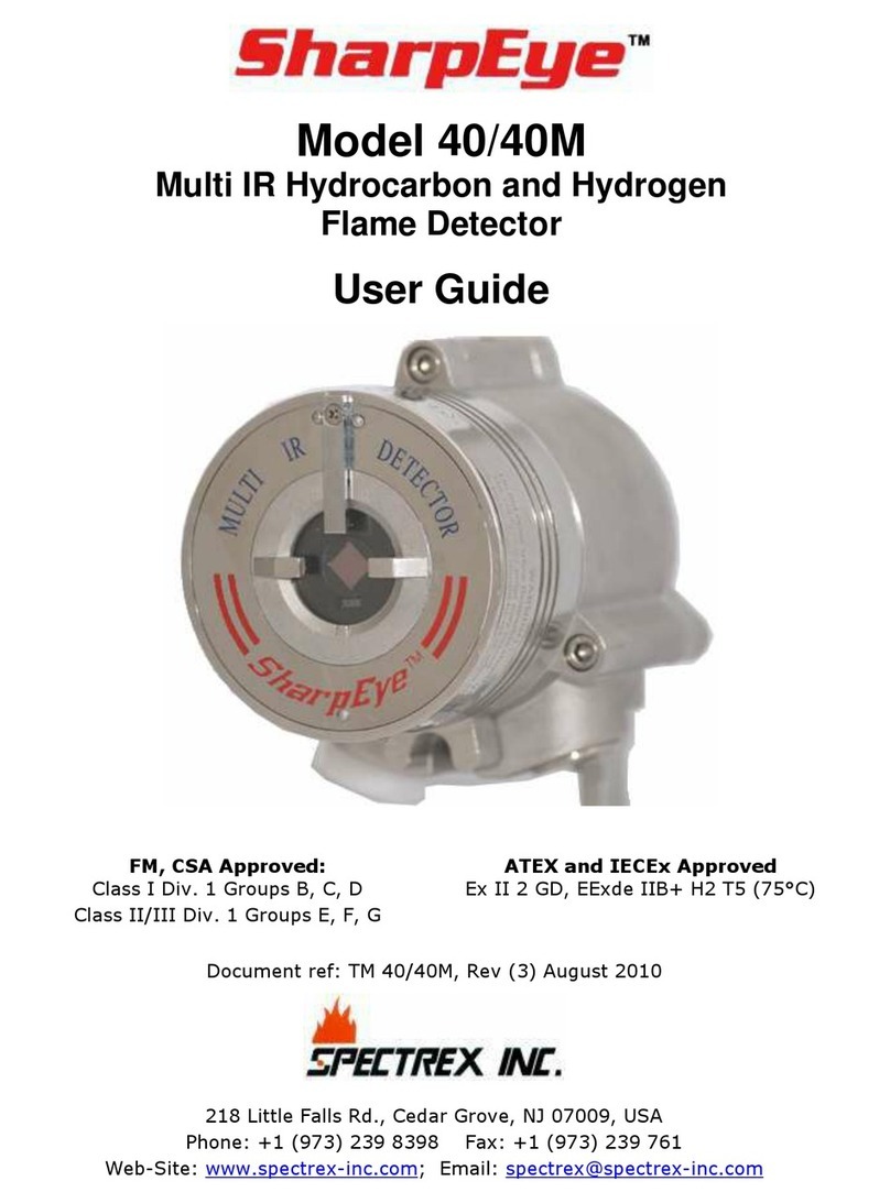
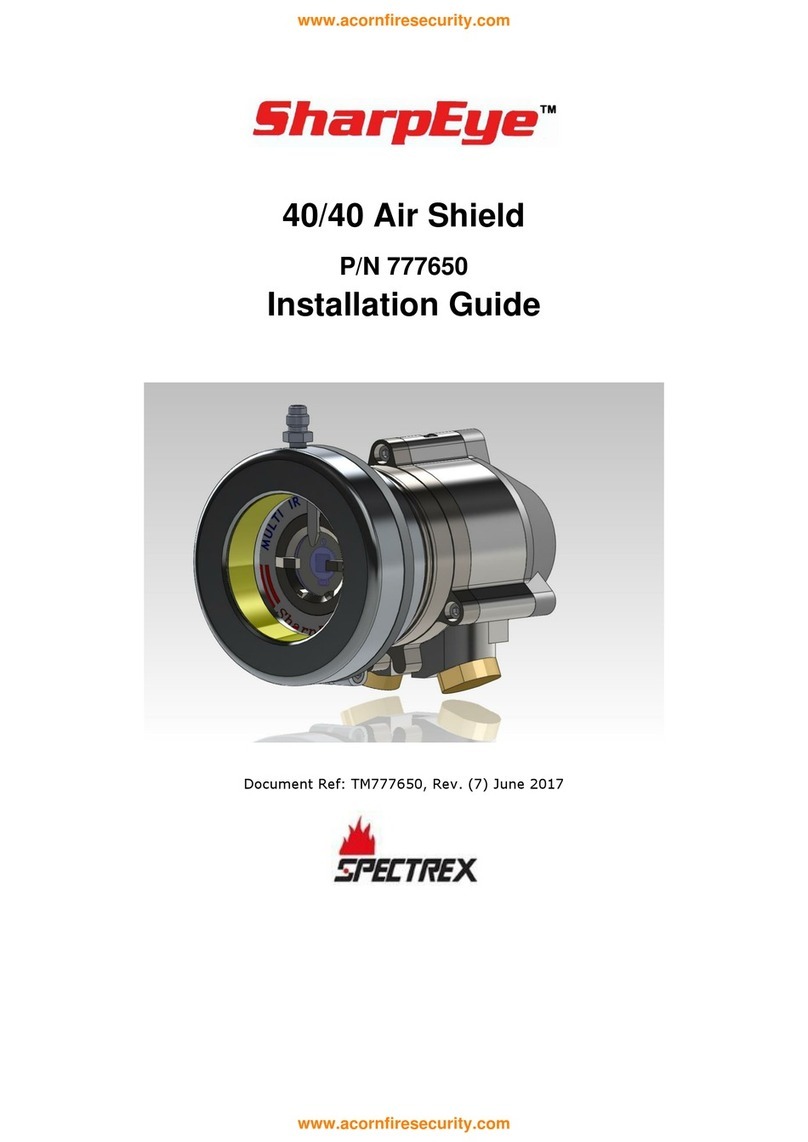
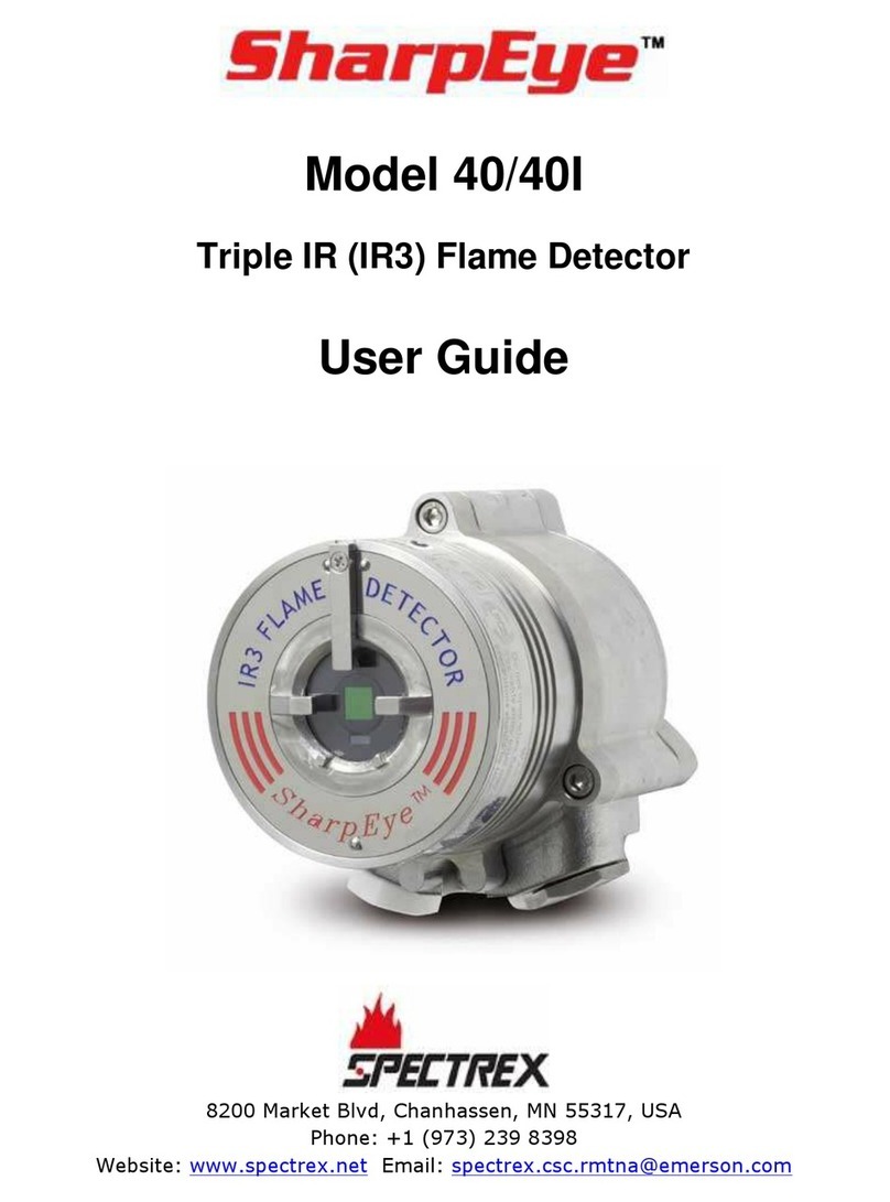
SharpEye 40 User manual

Legal Notice
The SPECTREX SharpEye Optical Flame Detector described in this document is the property of Rosemount.
No part of the hardware, software or documentation may be reproduced, transmitted, transcribed, stored in a
retrieval system or translated into any language or computer language, in any form or by any means, without prior
written permission of Rosemount.
While great efforts have been made to assure the accuracy and clarity of this document, Rosemount assumes no
liability resulting from any omissions in this document, or from misuse of the information obtained herein. The
information in this document has been carefully checked and is believed to be entirely reliable with all of the
necessary information included. Rosemount reserves the right to make changes to any products described herein
to improve reliability, function, or design, and reserves the right to revise this document and make changes from
time to time in content hereof with no obligation to notify any persons of revisions or changes. Rosemount does not
assume any liability arising out of the application or any use of any product or circuit described herein; neither
does it convey license under its patent rights or the rights of others.
Warranty
SPECTREX agrees to extend to Purchaser/Distributor a warranty on the SPECTREX supplied components of the
SharpEye products. SPECTREX warrants to Purchaser/Distributor that the products are free from defects in
materials and workmanship for a period of five (5) years, commencing with the date of delivery to
Purchaser/Distributor. SPECTREX expressly excludes damage incurred in transit from the factory or other damage
due to abuse, misuse, improper installation, or lack of maintenance or “Act of God” which are above and beyond its
control. SPECTREX will, upon receipt of any defective product, transportation prepaid, repair or replace it at its sole
discretion if found to have been defective when shipped. Said repair or replacement is SPECTREX’S sole liability
under this warranty and SPECTREX’S liability shall be limited to repair or replacement of the component found
defective and shall not include any liability for consequential or other damages. The customer is responsible for all
freight charges and taxes due on shipments both ways. This warranty is exclusive of all other warranties express or
implied.
TM40/40UFL Rev. (Al), February 2019
www.acornfiresecurity.com
www.acornfiresecurity.com

TM40/40UFL Rev. (Al), February 2019 v
Table of Contents
Table of Contents ............................................................................................ v
List of Figures ................................................................................................ ix
List of Tables................................................................................................... x
1About this Guide ...................................................................................... 11
1.1 Release History.....................................................................................12
1.2 Glossary and Abbreviations ....................................................................12
1.3 Notifications .........................................................................................14
2Product Overview .................................................................................... 15
2.1 Model and Types...................................................................................16
2.2 Features and Benefits ............................................................................18
2.3 Principles of Operation...........................................................................18
2.3.1 Sensing Elements ...........................................................................18
2.3.2 Detection Levels .............................................................................19
2.3.3 Heated Optics.................................................................................19
2.3.4 HART Protocol ................................................................................19
2.3.5 RS-485 Modbus ..............................................................................20
2.3.6 Product Certification........................................................................20
2.4 Performance Considerations ...................................................................23
2.4.1 Detection Sensitivity .......................................................................23
2.4.2 Cone of Vision ................................................................................25
2.4.3 False Alarm Prevention ....................................................................26
2.4.4 Visual Indicators .............................................................................27
2.4.5 Output Signals................................................................................27
2.4.6 Detector Status ..............................................................................28
2.4.7 Auxiliary Relay as End-of-Line ..........................................................30
2.5 Internal Detector Tests ..........................................................................30
2.5.1 Continuous Feature Test ..................................................................30
2.5.2 Response to Fault Indication ............................................................30
2.5.3 Built-In-Test (BIT) ..........................................................................31
3Installing the Detector ............................................................................ 33
3.1 General Guidelines ................................................................................33
3.1.1 Sensitivity......................................................................................33
3.1.2 Wiring ...........................................................................................33
www.acornfiresecurity.com
www.acornfiresecurity.com

vi SharpEye™ Ultra Fast UV/IR Flame Detector User Guide
3.1.3 Spacing and Location ......................................................................33
3.1.4 Environment ..................................................................................33
3.2 Aiming the Detector: .............................................................................34
3.3 Unpacking the Product...........................................................................34
3.3.1 Checking the Product Type...............................................................34
3.4 Required Tools......................................................................................34
3.5 Certification Instructions ........................................................................35
3.5.1 Special Instructions for Safe Use.......................................................35
3.5.2 General Instructions........................................................................36
3.6 Installation Cables ................................................................................36
3.6.1 Conduit Installation.........................................................................37
3.7 Installing the Tilt Mount .........................................................................38
3.7.1 Tilt Mount Specifications ..................................................................39
3.7.2 Tilt Mount Assembly ........................................................................39
3.8 Connecting the Detector ........................................................................41
3.8.1 Verifying the Detector Wiring ...........................................................42
3.9 Configuring Your Detector ......................................................................43
3.9.1 Alarm Delay ...................................................................................44
3.9.2 Address Setup ................................................................................44
3.9.3 Function Setup ...............................................................................45
3.9.4 Heated Optics.................................................................................45
4Operating the Detector ............................................................................ 47
4.1 Powering Up.........................................................................................47
4.2 Safety Precautions ................................................................................47
4.2.1 Default Functions Settings ...............................................................48
4.3 Testing Procedures................................................................................49
4.3.1 Automatic BIT Test .........................................................................49
4.3.2 Testing with Flame Simulator FS-1200 ..............................................49
5Maintenance and Troubleshooting ........................................................... 50
5.1 Maintenance.........................................................................................50
5.1.1 General Procedures .........................................................................50
5.1.2 Periodic Procedures .........................................................................50
5.1.3 Keeping Maintenance Records ..........................................................51
5.2 Troubleshooting....................................................................................51
Appendix A: Specifications ....................................................................... 53
A.1 Technical Specifications .........................................................................53
www.acornfiresecurity.com
www.acornfiresecurity.com

TM40/40UFL Rev. (Al), February 2019 vii
A.2 Electrical Specifications..........................................................................53
A.2.1 Electrical Input Protection ................................................................54
A.3 Outputs ...............................................................................................54
A.3.1 Electrical Interface ..........................................................................54
A.3.2 Electrical Outputs............................................................................55
A.3.3 Heated Optics.................................................................................56
A.4 Approvals.............................................................................................57
A.4.1 Hazardous Area Approvals ...............................................................57
A.4.2 Functional Approvals .......................................................................57
A.5 Mechanical Specifications .......................................................................57
A.5.1 Enclosure.......................................................................................58
A.5.2 Water and Dust Tight ......................................................................58
A.5.3 Electronic Modules ..........................................................................58
A.5.4 Electrical Connections (2 entries) ......................................................58
A.5.5 Dimensions ....................................................................................58
A.5.6 Weight ..........................................................................................58
A.6 Environmental Specifications ..................................................................58
A.6.1 High Temperature ...........................................................................58
A.6.2 Low Temperature............................................................................58
A.6.3 Humidity........................................................................................58
A.6.4 Salt Fog.........................................................................................59
A.6.5 Dust..............................................................................................59
A.6.6 Vibration........................................................................................59
A.6.7 Mechanical Shock............................................................................59
A.6.8 Electromagnetic Compatibility (EMC) .................................................59
Appendix B: Wiring Instructions............................................................... 61
B.1 General Instructions for Electrical Wiring..................................................61
B.2 61
B.3 Calculation Formula...............................................................................62
B.4 Typical Wiring Configurations .................................................................63
Appendix C: RS-485 Communication Network .......................................... 67
C.1 RS-485 Overview ..................................................................................67
Appendix D: Accessories ........................................................................... 69
D.1 Flame Simulator FS-1200.......................................................................69
D.1.1 Ordering Information.......................................................................69
D.1.2 Unpacking......................................................................................70
www.acornfiresecurity.com
www.acornfiresecurity.com

viii SharpEye™ Ultra Fast UV/IR Flame Detector User Guide
D.1.3 Operating Instructions.....................................................................70
D.1.4 Range ...........................................................................................71
D.1.5 Charging the Battery .......................................................................71
D.1.6 Battery Replacement .......................................................................72
D.2 Technical Specifications .........................................................................73
D.2.1 General .........................................................................................73
D.2.2 Electrical........................................................................................73
D.2.3 Physical .........................................................................................73
D.2.4 EMI Compatibility............................................................................73
D.3 Tilt Mount ............................................................................................74
D.4 Duct Mount ..........................................................................................75
D.5 Weather Cover .....................................................................................76
D.6 Air Shield.............................................................................................77
Appendix E: SIL-2 Features ...................................................................... 79
E.1 40/40UFL Flame Detector ......................................................................79
E.1.1 Safety Relevant Parameters .............................................................79
E.1.2 Guidelines for Configuring, Installing, Operating, and Service ...............79
Appendix F: End of Line Resistor .............................................................. 81
Technical Support ......................................................................................... 84
www.acornfiresecurity.com
www.acornfiresecurity.com

TM40/40UFL Rev. (Al), February 2019 ix
List of Figures
Figure 1: Horizontal Field of View ........................................................................25
Figure 2: Vertical Field of View............................................................................25
Figure 3: Indicator LED ......................................................................................27
Figure 4: Detector with Tilt Mount .......................................................................38
Figure 5: Tilt Mount Assembly.............................................................................39
Figure 6: Tilt Mount Assembly (dimensions in mm and inches)................................40
Figure 7: Detector with Cover Removed ...............................................................41
Figure 8: Wiring Terminals .................................................................................63
Figure 9: Typical Wiring for 4 Wire Controllers (Using Option 1 or 2 Wiring) .............64
Figure 10: 0–20mA Wiring Option 1 (Sink 4-Wire) –Default...................................65
Figure 11: 0–20mA Wiring Option 1 (Converted to Source 3-Wire) ..........................65
Figure 12: 0–20mA Wiring Option 1 (Non-isolated Sink 3-Wire) ..............................66
Figure 13: 0–20mA Wiring Option 2 and 3............................................................66
Figure 14: RS-485 Networking ............................................................................67
Figure 15: Flame Simulator FS-1200 ...................................................................69
Figure 16: Flame Simulator Battery Replacement ..................................................71
Figure 17: Tilt Mount .........................................................................................74
Figure 18: Duct Mount .......................................................................................75
Figure 19: Weather Cover ..................................................................................76
Figure 20: Air Shield..........................................................................................77
Figure 21: End of Line Resistor Assembly .............................................................81
www.acornfiresecurity.com
www.acornfiresecurity.com

x SharpEye™ Ultra Fast UV/IR Flame Detector User Guide
List of Tables
Table 1: Wiring Options .....................................................................................17
Table 2: Fuel Sensitivity Ranges..........................................................................24
Table 3: Immunity to False Alarm Sources ...........................................................26
Table 4: LED Indications ....................................................................................27
Table 5: Available Output Types..........................................................................28
Table 6: Detector Status ....................................................................................28
Table 7: Output Signals Versus Detector State......................................................29
Table 8: Results of a Successful BIT ....................................................................31
Table 9: Results of an Unsuccessful BIT ...............................................................32
Table 10: Tools .................................................................................................35
Table 11: USA Version .......................................................................................39
Table 12: European Version................................................................................39
Table 13: Model 40/40UFL Wiring Options ............................................................42
Table 14: Functions ...........................................................................................45
Table 15: Default Function Values .......................................................................48
Table 16: Results of Successful Flame Simulator Test ............................................49
Table 17: Troubleshooting Table .........................................................................51
Table 18: Electrical Specifications........................................................................54
Table 19: Contact Ratings ..................................................................................55
Table 20: 20mA Current Output ..........................................................................55
Table 21: Electromagnetic Compatibility (EMC) .....................................................59
Table 22: Maximum DC Resistance at 68°F/20ºC for Copper Wire ...........................61
Table 23: Wiring Length in ft/m ..........................................................................61
Table 24: Wiring Connections .............................................................................64
Table 25: Sensitivity Ranges...............................................................................71
Table 26: Immunity Tests ..................................................................................73
Table 27: Emission Tests....................................................................................74
www.acornfiresecurity.com
www.acornfiresecurity.com

About this Guide
TM40/40UFL Rev. (Al), February 2019 11
1About this Guide
This guide describes the SharpEye Model 40/40UFL Flame Detector and its
features and provides instructions on how to install, operate, and maintain the
detector.
Note:
This user guide should be read carefully by all individuals who have or
will have responsibility for using, maintaining, or servicing the
product.
This guide includes the following chapters and appendices:
•Chapter 1, About this Guide, details the layout of the guide, includes the
release history, a glossary and abbreviations, and explains how notifications
are used in the guide.
•Chapter 2, Product Overview, provides a general overview of the product,
principles of operation, and performance considerations.
•Chapter 3, Installing the Detector, describes how to install the detector
including preparations before installation, wiring, and mode settings.
•Chapter 4, Operating the Detector, describes how to power up and test
the detector. The chapter also lists safety precautions you should take when
operating the detector.
•Chapter 5, Maintenance and Troubleshooting, describes basic
maintenance, troubleshooting, and support procedures.
•Appendix A, Specifications, lists the detectors’technical and other
specifications.
•Appendix B, Wiring Instructions, lists the wiring instructions for
connecting the detector and also provides examples of typical wiring
configurations.
•Appendix C, RS-485 Communication Network, provides an overview of
the RS-485 communications network.
•Appendix D, Accessories, describes the accessories available for the
detector.
•Appendix E, SIL-2 Features, describes the special conditions for compliance
with EN 61508 for SIL-2 requirements according to TÜV.
•Appendix F, End of Line Resistor, describes the option of adding an end of
line resistor.
www.acornfiresecurity.com
www.acornfiresecurity.com

About this Guide
12 SharpEye™ Ultra Fast UV/IR Flame Detector User Guide
1.1 Release History
Rev
Date
Revision History
Prepared by
Approved by
0
October 2012
First Release
Ian Buchanan
Eric Zinn
1
March 2013
Second Release
Ian Buchanan
Eric Zinn
2
August 2013
Third Release
Ian Buchanan
Eric Zinn
3
May 2014
Fourth Release
Ian Buchanan
Eric Zinn
4
February 2015
Fifth Release
Ian Buchanan
Eric Zinn
5
June 2015
Sixth Release
Ian Buchanan
Eric Zinn
January 2016
Seventh Release
Ian Buchanan
Eric Zinn
7
July 2016
Eighth Release
Ian Buchanan
Eric Zinn
8
October 2016
Ninth Release
Jay Cooley
Ian Buchanan
9
January 2017
Tenth Release
Jay Cooley
Ian Buchanan
10
February 2017
Eleventh Release
Jay Cooley
Ian Buchanan
Ak
March 2018
Twelfth Release
Michal Heller
Udi Tzuri
Al
February 2019
Thirteenth Release
Michal Heller
Udi Tzuri
1.2 Glossary and Abbreviations
Abbreviation/Term
Meaning
Analog Video
Video values are represented by a scaled signal
ATEX
Atmosphere Explosives
AWG
American Wire Gauge
BIT
Built-In-Test
CMOS
Complementary Metal-Oxide Semiconductor image
sensor
Digital Video
Each component is represented by a number
representing a discrete quantization
DSP
Digital Signal Processing
EMC
Electromagnetic Compatibility
EMI
Electromagnetic Interference
EOL
End of Line
FOV
Field of View
HART
Highway Addressable Remote Transducer –
communications protocol
IAD
Immune at Any Distance
IECEx
International Electro-Technical Commission
Explosion
www.acornfiresecurity.com
www.acornfiresecurity.com

About this Guide
TM40/40UFL Rev. (Al), February 2019 13
Abbreviation/Term
Meaning
IP
Internet Protocol
IPA
Isopropyl Alcohol
IR
Infrared
IR3
Refers to the 3 IR sensors in the VID
JP5
Jet Fuel
LED
Light Emitting Diode
MODBUS
Serial communications protocol using Master-Slave
messaging
N/A
Not Applicable
N.C.
Normally Closed
NFPA
National Fire Protection Association
N.O.
Normally Open
NPT
National Pipe Thread
NTSC
National Television System Committee (a color encoding
system)
PAL
Phase Alternation by Line (a color encoding
system)
P/N
Part Number
RFI
Radio Frequency Interference
RTSP
Real Time Streaming Protocol
SIL
Safety Integrity Level
UNC
Unified Coarse Thread
VAC
Volts Alternating Current
www.acornfiresecurity.com
www.acornfiresecurity.com

About this Guide
14 SharpEye™ Ultra Fast UV/IR Flame Detector User Guide
1.3 Notifications
This section explains and exemplifies the usage of warnings, cautions, and notes
throughout this guide:
Warning:
This indicates a potentially hazardous situation that could result in
serious injury and/or major damage to the equipment.
Caution:
This indicates a situation that could result in minor injury and/or
damage to the equipment.
Note:
This provides supplementary information, emphasizes a point or
procedure, or gives a tip to facilitate operation.
www.acornfiresecurity.com
www.acornfiresecurity.com

Product Overview
TM40/40UFL Rev. (Al), February 2019 15
2Product Overview
Model 40/40UFL provides a combination of UV and IR sensors, where the IR
sensor operates at a wavelength of 2.5–3.0µm. It can detect hydrocarbon-based
fuel and gas fires, hydroxyl and hydrogen fires, as well as metal and inorganic
fires with ultrafast ability to detect fire or an explosion in less than 20msec.
Warning:
The detector is not field-repairable due to the meticulous alignment
and calibration of the sensors and the respective circuits. Do not
attempt to modify or repair the internal circuits or change their
settings, as this will impair the system’s performance and void the
SPECTREX product warranty.
All 40/40 series detectors include a heated optical window for improved
performance in ice, snow, and condensation conditions.
Detection performance can be easily adapted to all environments, applications,
and requirements by changing the detector’s configuration parameters. Adjusting
these parameters, as well as performing other maintenance and monitoring
tasks, is possible by means of RS-485 based Modbus communication or HART
communication (in models with 0–20mA output).
The detector enclosure is ATEX certified Exd flameproof with an integral,
segregated, rear, Exe terminal compartment (avoiding exposure of the sensors
and electronics to the surrounding environment). Hence the combined approval:
Ex II 2G D
Ex db eb op is IIC T5 Gb
Ex tb op is IIIC T96°C Db
(–55°C ≤ Ta ≤ +75°C)
or
Ex II 2G D
Ex db eb op is IIC T4 Gb
Ex tb op is IIIC T106°C Db
(–55°C ≤ Ta ≤ +85°C)
The SharpEye 40/40 detector is designed to operate as a stand-alone unit
directly connected to an alarm system or an automatic fire extinguishing system.
The detector can also be a part of a more complex system, where many detectors
and other devices are integrated through a common control unit.
www.acornfiresecurity.com
www.acornfiresecurity.com

Product Overview
16 SharpEye™ Ultra Fast UV/IR Flame Detector User Guide
2.1 Model and Types
The 40/40UFL UV/IR flame detector is provided in various configurations
depending on:
•Wiring options
•Temperature ranges
•Type of cable entries
•Housing material type
•Required approval
The configuration detail is included in the product part number on the product
label and takes the form: 40/40UFL-XXXXX, where XXXXX defines the model
according to the above requirements.
To modify the default or pre-ordered configuration and perform maintenance
tasks, please refer to the HART Protocol TM777030, the RS-485 Manual TM
777050 or TM777070.
The part numbers (P/N) are defined as:
Aluminum housing is not available in the FM version.
www.acornfiresecurity.com
www.acornfiresecurity.com

Product Overview
TM40/40UFL Rev. (Al), February 2019 17
Table 1 describes the wiring options in detail.
Table 1: Wiring Options
Wiring
Option
Connections Provided
1
Power
Analog
Output
Fault
Relay
N.C.
Alarm
Relay
N.O.
0–20mA
Sink
RS-485
HART
2
Power
Analog
Output
Fault
Relay
N.C.
Alarm
Relay
N.O.,
N.C.
0–20mA
Source
RS-485
HART
3
Power
Analog
Output
Fault
Relay
N.O.
Alarm
Relay
N.O.,
N.C.
0–20mA
Source
RS-485
HART
4
Power
Analog
Output
Fault
Relay
N.C.
Alarm
Relay
N.O.
Auxiliary
N.O.
RS-485
-
5
Power
Analog
Output
Fault
Relay
N.O.
Alarm
Relay
N.O.
Auxiliary
N.O.
RS-485
-
Note:
Wiring option 1 is the default. The mA “Sink”output can be altered to
“Source”type, with a link between terminals 1 and 8. No other wiring
options can be changed onsite.
Product number 40/40UFL-321SC has the following options:
•Wiring Option: 3 (Power, Analog Output, RS-485, 0–20mA [Source] with the
HART protocol, Fault Relay [N.O.], Alarm Relay [N.O., N.C.])
•Temperature Range: 2 (85°C)
•Cable Entry: 1 (M25)
•Housing: S (Stainless Steel)
•Approval: C (ATEX, IECEx)
Note:
Check your specific part numbers against the information in Checking
the Product Type on page 34.
www.acornfiresecurity.com
www.acornfiresecurity.com

Product Overview
18 SharpEye™ Ultra Fast UV/IR Flame Detector User Guide
2.2 Features and Benefits
•UV/IR Dual Sensor
•High Speed Response: 20msec response to flash fire
•Built-In-Test (BIT): Automatic (see Built-In-Test (BIT) on page 31).
•Heated Window: Prevents effects of ice, snow, and condensation.
•Electrical Interface:
•Dry contact relays
•Communication network RS-485
•0–20mA output
•HART Protocol: Communication protocol (see HART Protocol on page 19).
•Exde: Integral junction box for easy wiring.
•SIL-2: TÜV approved.
•Hazardous Area Certification: ATEX, IECEx, FM.
•Functionality Approval:
•FM approved per FM3260
•EN54-10 approved by VdS
•Accessories are approved as part of ATEX and IECEx approval.
2.3 Principles of Operation
This section describes the 40/40UFL principles of operation.
The Model 40/40UFL Flame Detector is an electronic device designed to sense the
occurrence of fire and flames and subsequently activate an alarm or an
extinguishing system directly or through a control circuit.
The UV/IR Radiation Flame Detector is a dual spectrum optical detector sensitive
to 2 separate ranges of the radiation spectrum, both of which are present in fires.
The detector monitors the protected volume by measuring the radiation intensity
in it, within 2 frequency ranges of the electromagnetic spectrum; namely the
Ultra-Violet (UV) and the Infra-Red (IR).
The detector integrates 2 dependent channels in which appropriate detection
pulses are registered and further analyzed for frequency, intensity, and duration.
2.3.1 Sensing Elements
The IR sensor in Models 40/40UFL is sensitive to radiation over the range of 2.5–
3.0 microns where the H2emission has a unique spectral peak that enables
detection of hydrocarbon fires, gas fires, hydroxyl, and hydrogen fires, as well as
metal and inorganic fires.
The UV sensor is sensitive to radiation over the range of 0.185–0.260µm. The UV
Channel incorporates a special logic circuit that eliminates false alarms caused by
solar radiation and other non-fire UV sources. Furthermore, the UV channel’s
sensitivity is stabilized over the working temperature range.
www.acornfiresecurity.com
www.acornfiresecurity.com

Product Overview
TM40/40UFL Rev. (Al), February 2019 19
2.3.2 Detection Levels
Simultaneous detection of radiation in both the UV and the IR channels, with an
intensity that exceeds the detector’s preset Warning level results in a Warning
signal.
Simultaneous detection of radiation in both the UV and the IR channels, with an
intensity that exceeds the detector’s preset Alarm level results in an Alarm signal.
Simultaneous detection of radiation in both the UV and the IR channels, with an
intensity that exceeds the detector’s preset Flash-Fire Detection level results in
an immediate Alarm signal.
Since the preset dual range and level of radiation, as well as the flickering
pattern, are characteristics of real fire, all other radiation sources apart from
actual fire are not detected, thus avoiding false alarms.
2.3.3 Heated Optics
The SharpEye 40/40 Flame Detector uses heated optics. The heater increases the
temperature of the optical surface by 5–8°F / ~3–5°C above the ambient
temperature to improve performance in ice, condensation, and snow conditions.
The heated optics can be set to one of the following:
•Not operated.
•On continuously.
•Automatic, per temperature change (default): you can define the start
temperature below which the window is heated. (The default is 41°F/5°C.)
This temperature can be defined between 32°F/0°C to 86°F/30°C. The
heating stops when the temperature is 27°F/15°C above the start
temperature.
For more information, see Configuring Your Detector on page 43.
2.3.4 HART Protocol
The 40/40 Flame Detectors use the HART protocol.
HART Communication is a bi-directional industrial field communication protocol
used to communicate between intelligent field instruments and host systems.
HART is the global standard for smart process instrumentation and the majority
of smart field devices installed in plants worldwide are HART-enabled. HART is
available in wiring options 1, 2, and 3 (see Table 1 on page 17).
HART technology is easy to use and very reliable.
Through the HART connection, you are able to perform:
•Detector setup
•Detector troubleshooting
•Detector health and status
For more details, refer to the HART Manual TM 777030.
www.acornfiresecurity.com
www.acornfiresecurity.com

Product Overview
20 SharpEye™ Ultra Fast UV/IR Flame Detector User Guide
2.3.5 RS-485 Modbus
For more advanced communications, the 40/40UFL detector has an RS-485
Modbus-compatible output that provides data communication from a network (up
to 247 detectors) to a host computer or universal controller for central
monitoring. This feature allows for reduced installation costs, easy maintenance,
and local or remote diagnostic tools.
2.3.6 Product Certification
The 40/40UFL Flame Detectors have the following certifications:
•ATEX, IECEx, page 21
•FM, page 21
•SIL-2 (TÜV) , page 21
•EN54-10, page 21
•Inmetro (UL), page 22
www.acornfiresecurity.com
www.acornfiresecurity.com
This manual suits for next models
1
Table of contents
Other SharpEye Security Sensor manuals
Popular Security Sensor manuals by other brands

Ortech
Ortech OL-S instruction manual
Alula
Alula RE309 quick start guide
Powerfix Profi
Powerfix Profi IAN 40111 Operation and safety notes
Endress+Hauser
Endress+Hauser nivotester FTL 325 P operating instructions
yellow jacket
yellow jacket AccuProbe 69320 Operation and maintenance manual
Wavetronix
Wavetronix SmartSensor Matrix user guide
Hama
Hama 186434 operating instructions
Scott Safety
Scott Safety PAK-ALERT Operation and maintenance instruction manual
U-Prox
U-Prox PIR quick start guide

Rohm
Rohm BH1730FVC-TR Technical notes
Homematic IP
Homematic IP HmIPW-SMI55 Installating instruction and operating manual
PCE Instruments
PCE Instruments PCE-FHM 10 manual


