SHARPSTAR 150HNT User manual
Collimation of the SharpStar 150HNT
【Preparation is Required before Collimation】
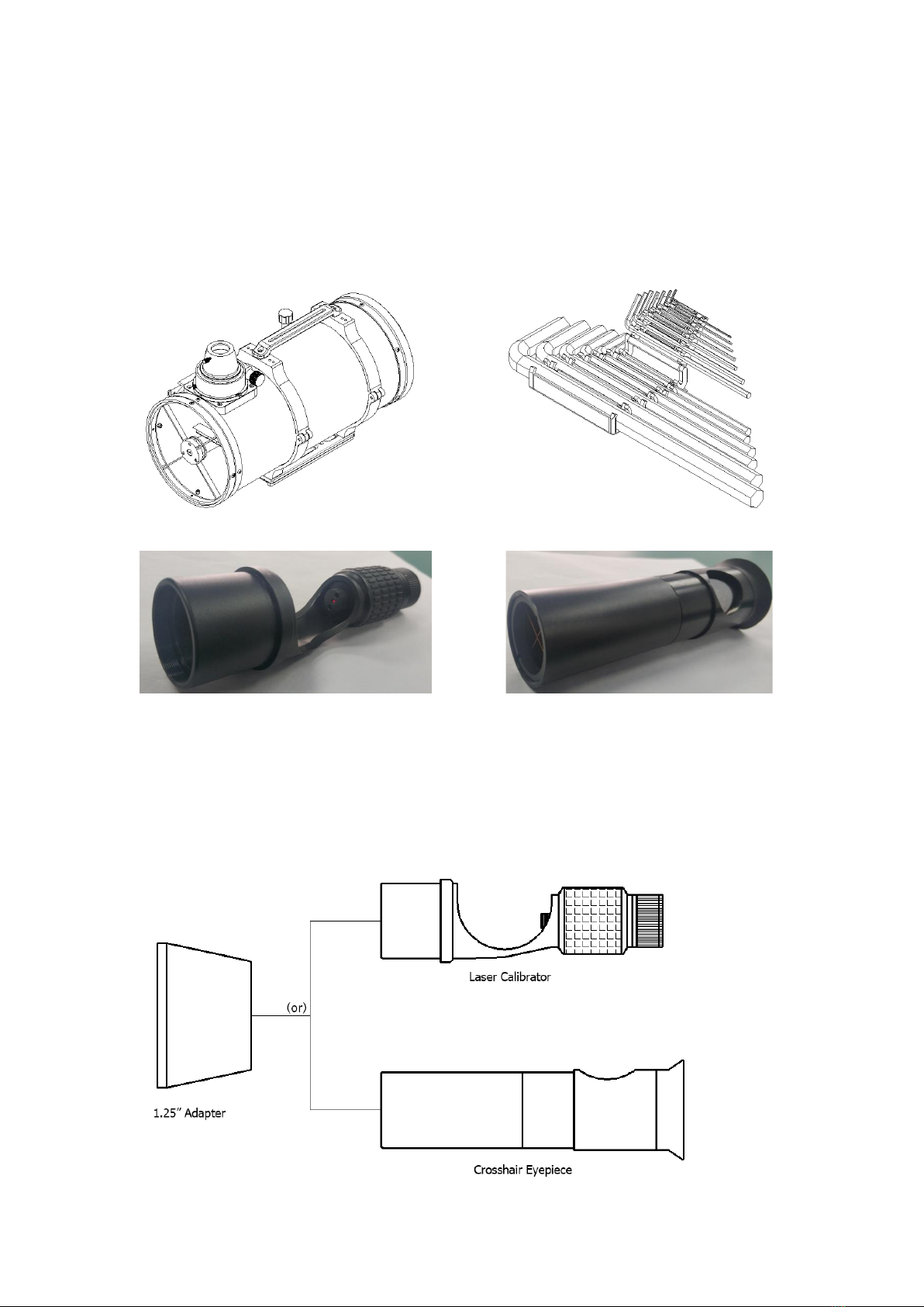
Sharpstar 150 Hyperboloid Newtonian Reflector, Allen Wrenches, Laser Calibrator, Crosshair
Eyepiece, 150 Reducer-specific tool, Depth measuring tool.
Sharpstar 150 Hyperboloid Newtonian Reflector Allen Wrench
Laser Calibrator Crosshair Eyepiece
【Connection Way】

【Preparation for Collimation】
Owing to the existence of diopter in the reducer,the reducer assembly must be removed in
order to collimate the 150HNT. Put the Reducer removing specific tool with its two sharp points
into the two holes in the reducer group frame accordingly, and then turn the tool to take the
reducer group off, now only unscrew Reducer assembly and Re-install connector ring to focuser
and then conical 1.25” eyepiece adapter to focuser. Now follow the steps like collimating a
Newtonian telescope but more precision adjustment required due to low focal ratio of Primary
Mirror( F/2.8).
Reducer Group 150 Reducer-specific Tool
STEP 1:
Collimation is critical to obtaining the best performance from your telescope. This
telescope has already been collimated at factory but it might have change due to transportation,
if the screws are not properly locking down the mirrors after collimation, or a component may
be loose somewhere in the optical train.
Now at Secondary mirror collimating unit, Keep in mind that the secondary mirror has
three degrees of freedom: Tilt, Rotation, and Longitudinal adjustment. For Longitudinal and
Rotational adjustment of secondary mirror, By adjusting the central screw, adjust how far the
spider disk of the secondary mirror from the stainless steel top-surface, great if the distance is
5mm( Factory Set) as the three set screws in the spider disk contact with the top-surface
slightly. If not 5mm then only use depth gauge or spacer gauge to reset to 5mm gap and lock
the central screw. Tilt is controlled by three screws behind secondary mirror.

SETP 2: Primary Mirror cell Back plate.
Now go to Primary mirror cell back plate as look like in figure below. PM cell back plate
has the three small screws( For Tilt) and three large screws(For locking) for collimation, all six
screws should be tight.
【Laser Collimation】
SETP 3: Insert the laser calibrator into the 1.25” adapter.
SETP 4: A laser produce a red dot will be shown near the primary mirror center dot. Using
the wrench and hand adjust the three collimation screws on the cross of secondary mirror to
change its position so that the laser dot should move and coincide with the dot marking the
center of the circle in the primary mirror and pre-tighten them to hold the secondary mirror.(see
figure below).

SETP 5:
Next, adjust the three set screws on the cross of secondary mirror to center the laser dot on
the black circle(diagonal section on laser), and pre-tighten them to hold the secondary mirror
(from slightly contact in Step 1).(see figure below).
SETP 6:
It then becomes necessary to Go to PM cell back plate and loosen very little the three
large screws and adjust carefully little movement the three small screws to further center the
dot, and tighten the three large screws to hold this adjustment. Note the location of the red dot
should be at center, in relation to the black circle or the location of the feedback red dot provided
by laser calibrator in relation to the central hole at primary mirror.

SETP 7: (This step may not be required)
Because the short focal ratio(F/2.8) can lead to a more sensitive light axis, and thus the
adjusted axis in Step 6 may be offset again in the process of tightening the small screws on the
back circle. Now further fine adjustment is required at focuser collimating screws to re-center
the dot.
【Crosshair Eyepiece Collimation】
See STEP 1 and STEP 2 in Laser Collimation, which aren't repeated here.
STEP 3: Insert the crosshair eyepiece into the 1.25” adapter. Insert white paper in telescope
tube under focuser.
Table of contents


