SHARPY 20R User manual
1Please read the manual carefully before use. 350W beam pattern
lamp three in one shaking head lamp
an instruction manual
(color display, touch operation)


catalogue
Chapter 1 precautions and installation.......................................... 1
1. Maintenance............................................. 1
2. Declaration......................................... 1
3. Precautions for products.......................................... 1
4. Product introduction........................................ 1
5. Signal line connection (DMX)................................................... 2
6. Installation of lamps........................................ 2
Chapter 2 panel operation........................................ 3
1. General......................................... 3
2. Operation......................................... 3
1. Use visual touch or encoder to operate lamps........................................ 3
2. Parameter value input......................................... 3
3. Set Boolean parameters........................................ 4
4. Sub page (parameter).................................................................... 4
3. Function operation and parameter setting........................................ 4
1. Set DMX address code.......................................... 4
2. Set the working mode of lamps.......................................... 5
3. Setting panel display settings.......................................... 6
4. Test lamps.......................................... 6
5. Setting the working parameters of lamps.......................................... 7
6. Check the current status of lamps.......................................... 7
Chapter 3 channel description........................................ 8
1. Channel table.......................................... 8
Chapter 4 common faults and precautions for use........................................ 11
1. Common fault handling........................................ 11
2. Precautions for use........................................ 11

Chapter 1 precautions and installation
1. Maintenance1. Maintenance
The lamp shall be kept dry to avoid working in humid environment.
Intermittent use will effectively prolong the service life of the lamp.
In order to obtain good ventilation effect and lighting effect, pay attention to
regularly cleaning the fan, fan net and lens.
Do not wipe the lamp shell with alcohol or other organic solvents to avoid damage.
2. Declaration2. Declaration
This product has good performance and complete packaging when leaving the
factory.All users shall strictly abide by the warnings and operating instructions
stated above. Any damage caused by misuse is not within the warranty of the company,
and the faults and problems caused by ignoring the operating manual are not within
the scope of the distributor's responsibility.
This manual is subject to technical changes without notice.
3. Product precautions3. Product precautions
In order to ensure the service life of the product, the product shall
not be placed in a wet or leaking place, nor shall it work in an
environment with a temperature of more than 60 ℃
Do not place the product in a place easy to loosen or shake.
In order to avoid the danger of electric shock, please ask a professional for
maintenance of this product.
When the bulb is used, the change of power supply voltage shall not exceed ±10%.
If the voltage is too high, the service life of the bulb will be shortened. If
the voltage is too low, the light color of the bulb will be affected.
After power failure, the lamp shall be fully cooled after 20 minutes before it
can be powered on again.
To ensure the normal use of this product, please read this instruction carefully.
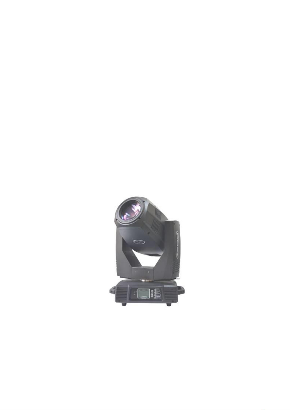
4. Product introduction4. Product introduction
Light source power: 380W;
Rated power: 500W (high efficiency and reliable switching power supply);
Power supply: high efficiency and reliable switching power supply;
Color disk: one color disk, each color disk is composed of 14 color chips + white
light;
Pattern disc: 14 pattern effects, 9 rotating pattern effects;

Effect wheel: a rotatable 8 prism and a 6-sided array of mirrors;
Dimming: 0-100% electronic dimming;
Large adjustable range of beam angle;
Stroboscopic: support mechanical stroboscopic and adjustable speed stroboscopic
effects, and support stroboscopic macro functions;
Lens group optical system, electric focusing, beam angle 3.8 °- 45 °, linearly
adjustable;
Photoelectric reset system is adopted, which can automatically retrieve and reset
in case of accidental misoperation;
Horizontal 540 °, resolution 8bit / 16bit;
Vertical 270 °, resolution 8bit / 16bit;
Overheating protection;
Control mode: DMX512 / master-slave / automatic;
Protection grade: IP20;
5. Signal line connection (DMX)5. Signal line connection (DMX))
Use RS-485 cables that meet the specifications: shielded, 120ohm characteristic
impedance, 22-24 AWG, low capacitive reactance. Do not use microphone cables or
cables with different specified characteristics. The terminals must be connected
with 3 or 5-pin XLR male / female connectors. A 120ohm impedance matching resistance
(minimum 1 / 4 W) must be inserted between terminals 2 and 3 of the terminal plug.
Important: wires shall not contact each other or metal shell.
Figure 1 DMX signal line connection diagram
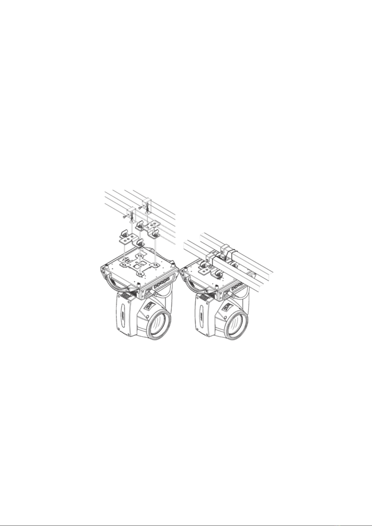
6. Lamp installation6. Lamp installation
Lamps can be placed horizontally, hung obliquely and upside down. Pay attention
to the installation method when hanging obliquely and upside down
As shown in Figure 2, before positioning the lamp, ensure the stability of the
installation site. During reverse hanging installation, ensure that the lamp does
not fall on the support frame. It is necessary to use safety rope to pass through
the support frame and lamp handle for auxiliary hanging to ensure safety and prevent
the lamp from falling and sliding.
During the installation and commissioning of lamps, pedestrians are not allowed
to pass below. Regularly check whether the safety rope is worn and whether the hook
screw is loose.
If the lamp falls due to unstable hanging and installation, our company will not
bear any responsibility.
chart2 Schematic diagram of upside down lamps

Chapter 2 panel operation
1. General1. General
The schematic diagram of the lamp panel is shown in Figure 3 (this diagram is a 4-key key).
The TFT display screen on the left supports touch operation, and the 4-key or 5-key keys or encoder
knob on the right can directly operate the lamp or set system parameters.
The display and operation are similar to "Android operating system". If the product you select
supports touch operation, you can click the corresponding item with your fingertips or blunt objects.
Note: do not use sharp or sharp objects to click on the display screen to prevent damage.
chart3 Display panel diagram
2. Operation2. Operation
1. Use visual touch or encoder to operate lamps1. Use visual touch or encoder to
operate lamps
The left area is TFT display area and touch area. Click the panel content with
your finger or blunt hardware to complete parameter setting or view status.
The right area is the "rotary encoder" as auxiliary input. If you do not use the
touch function of TFT, you can rotate the encoder to select the item to be set
or viewed, then press the encoder to confirm the selection, rotate the encoder
to set the parameter value again, and finally press the encoder protection
setting to complete the operation.
2. Parameter value input2. Parameter value input
When the selected parameter item needs to enter a value, the window as shown
in Figure 4 will open:
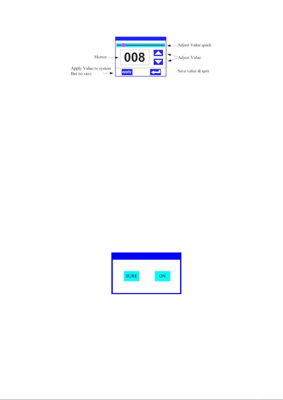
chart4 Value setting page
Set value:You can directly pull the slider to quickly set the required value,
or you can click the "up" or "down" button on the right to accurately set the
required value Or rotate the "rotary encoder" on the right to set it;
Application value:When the data is set through the "up" or "down" buttons, then
press the button in the lower left corner“apply”Application key, the value is
sent to the lamp immediately, but the value is not saved;
Save value:At any time, click the "OK" button in the lower right corner, that
is, save the current value to the internal memory, and apply the saved value
to the lamp next time.
3. Set Boolean parameters3. Set Boolean parameters
When the set parameter is Boolean (such as on or off)When pressing, you can directly
click the corresponding item to switch the parameter value, and the modified
parameters will be saved to the internal memory. Press the parameter option on
the right, and the corresponding option will become gray. When you release your
hand, the corresponding parameters will be changed and saved. If the pressed
parameter option is not the parameter you want to change, you can move your finger
to other parts of the screen, and the corresponding parameters will not be
changedChange.
Important Boolean parameters will be set through the confirmation window, as shown
in Figure 5 below:
chart5 OK input window
4. Sub page (parameter)4. Sub page (parameter)
Click the main menu to enter the sub menu page, as shown in Figure 6. There are
6 sub pages, including different types of parameters or states, as follows:
Address: set the DMX address of the lamp;
Workmode: set the working mode and master / slave mode of the lamp;
Display: set the parameters of the display interface, such as language,
screensaver mode, etc;

Test: it is mainly used to test lamps and simulate the values of corresponding
DMX channels. Refer to the channel menu for the corresponding functions of
channel values;
Advance: set the operating parameters of lamps;
Status: view the current status of lamps.
chart6 Page graph
3. Function operation and parameter setting3. Function operation and
parameter setting
Enter the setting interface, as shown in Figure 6:
In the main interface, you can touch six buttons to enter the corresponding
parameter setting interface.
In the parameter setting interface, you can press the blue option on the left to
quickly switch to other setting interfaces.
1. Set DMX1. Set DMXAddress code
Click and select "address (addr)" to enter the DMX address code setting page.
The address code value range is 1 ~ 512, and the address code cannot be greater than
(512 channel number), otherwise the lamp will not be controlled. The specific setting
operations are as follows:
Enter the DMX setting interface, as shown in Figure 7, click the white area on
the right to pop up the parameter setting window as shown in Figure 4. You can directly
pull the red square of the progress bar to quickly set the DMX address code value,
or press the "up" or "down" key to accurately set the desired DMX address code, and
then press the Enter key to save the data to complete the address code setting
operation.
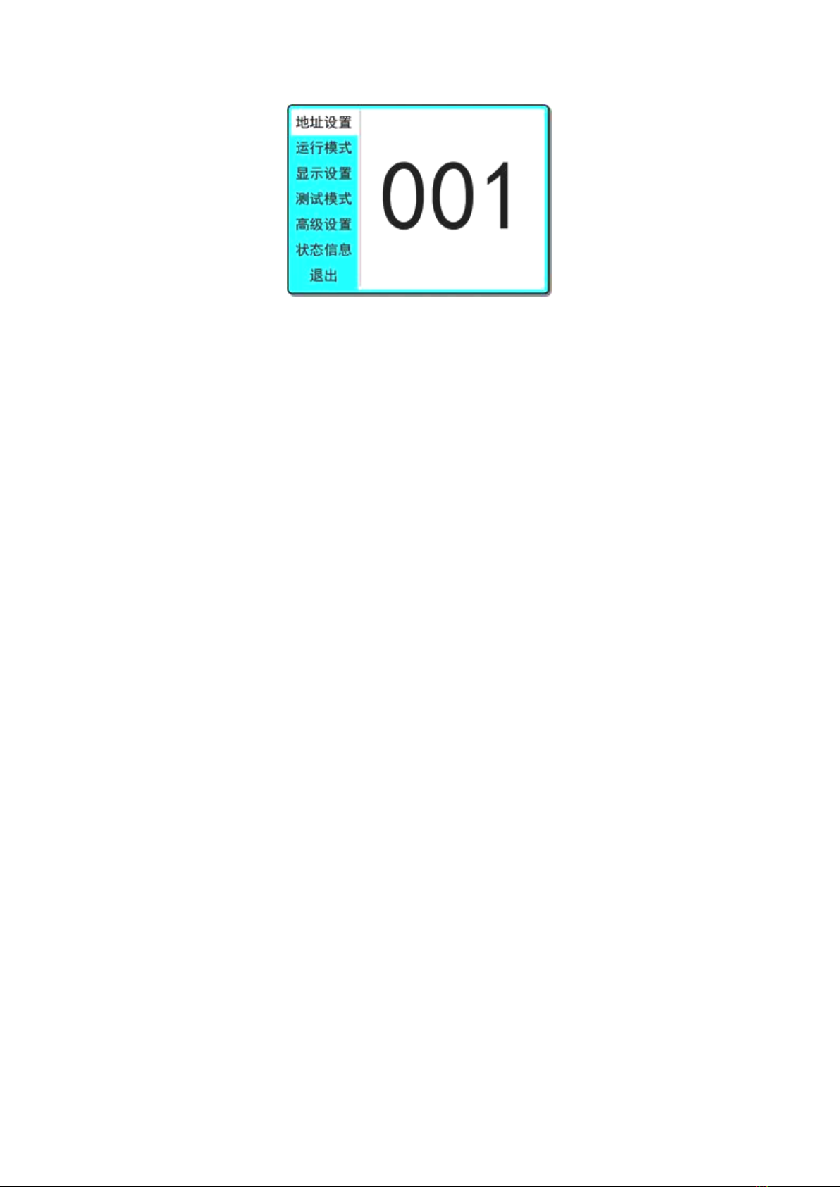
chart7 Address code setting page
2. Set the lamp working mode2. Set the lamp working mode
The operation mode, control light gun and channel mode of the lamp can be set
through the page shown in Figure 8. The lamp supports three operation modes (DMX
mode, self-propelled mode and voice control mode). Please refer to the previous
section for detailed parameter value settings. The specific parameters are described
as follows:
DMX mode:In this mode, the lamp receives data from the console and operates
according to the data of the console (common mode);
Self propelled mode:In this mode, the lamp does not receive console data and runs
by itself with an internal fixed program;
Voice control mode:In this mode, the lamp does not receive console data. When
there is a strong sound in the environment, the lamp will run a scene, otherwise
it will maintain the last scene.
Master slave selection:"Master-slave selection" only takes effect when the lamp
works in "self-propelled mode" or "voice control mode". When this option is
turned off, the internal program data of lamp operation will not passDMXThe
data line is sent to other lamps. When it is turned on, the data will be sent
to other lamps in real time, and other lamps (slave) of the same type will run
synchronously with the lamp (host).
Lamp switch:Through this setting, the opening and closing of the lamp can be
controlled. Note that the lamp can not be opened and closed too frequently, which
will reduce the service life of the lamp. The time interval between turning on
and off the lamp has been limited to30Seconds, that is, after the light bulb
changes state30Within seconds, multiple on and off operations are ignored, and
only the last operation is retained.
Channel mode:The lamp supports two channel modes, "simplified" channel saves
several channels for setting motor speed, and each operation mode channel saves
energyDMXFor channel utilization, the "extended" channel is more than the
"thin" channel, as described above. Please refer toThe first3chapterChannel
table description for.

chart8 Operation mode setting page
3. Set panel display settings3. Set panel display settings
The lamp supports bilingual Chinese and English, inverted lamp display, etc.
enter the corresponding parameter setting as shown in Figure 9:
Language:Select Chinese or English to display, and the selection will take effect
immediately.
Screen saver:When the lamp is not set for a period of time(10Seconds), the screen
will enter the screensaver state. When this item is set to "mode"1”When, the
screen saver status is off screen (black screen); set to "mode"2”When, the screen
saver status is displayedDMXAddress code (DMXMode) or display icon
(self-propelled or voice control mode); when it is set to "off", it does not
enter the screen saver and displays the main interface.
Screen rotation:Select whether the screen is displayed in108Degree rotation
display. When the lamp is upside down, this option can be turned on to make the
display more intuitive and clear.
Touch screen switch:When "off" is selected, the touch screen function of the
display screen is turned off, and only the encoder knob can be used.
Touch screen correction:Click this item to enter the correction page to re correct
the touch accuracy of the touch screen. Under normal circumstances, please do
not enter this page.
chart9 Display settings page
4. Test lamps4. Test lamps
Enter the page as shown in Figure 10, and the lamp enters the test mode. In this
mode, the lamp does not receive DMX console data. The parameters on the page
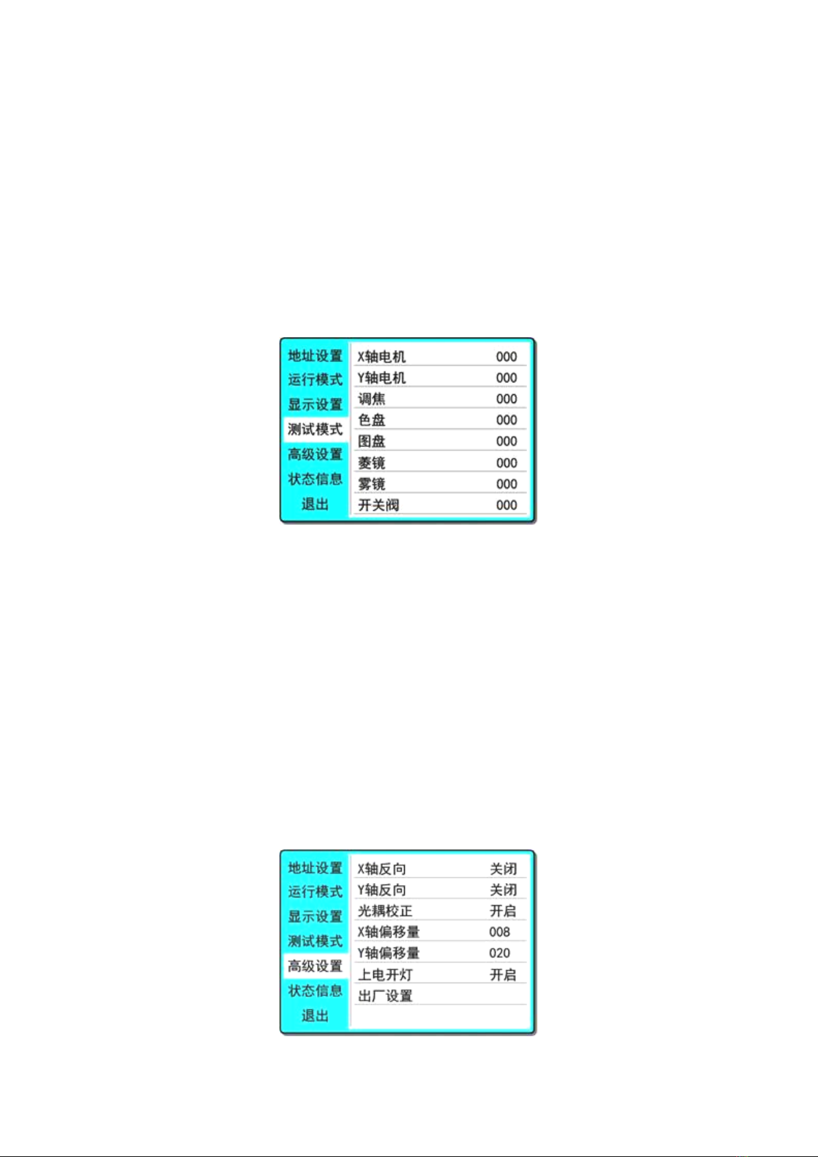
correspond to the value of DMX channel. The data of corresponding parameter items
can be changed to control the operation of the lamp:
X-axis motor (Pan): value (0 ~ 255);
Y-axis motor (tilt): value (0 ~ 255);
Focus motor: value (0 ~ 255);
Color: value (0 ~ 255);
Drawing disc (gobo): value (0 ~ 255);
Prism: value (0 ~ 255). When the prism is inserted, the prism rotation starts at
the same time;
Fog mirror (Frost): value (0 ~ 255);
On off valve (STROBE): value (0 ~ 255).
chart10 Test mode page
5. Set the working parameters of lamps5. Set the working parameters of lamps
Enter the page shown in Figure 11 to adjust the field parameters of lamps to
facilitate the field installation of lamps, etc
Pan invert of x-axis motor: the initial position and end position of x-axis motor are exchanged;
Tilt invert of y-axis motor: the initial position and end position of y-axis motor are exchanged;
Optocoupler correction: select whether to use the optocoupler to automatically
correct the position of X and Y. when "on", if the X or Y axis motor is out of
step, the lamp will automatically correct back to the position it should be in;
Pan offset: sets the offset angle of the initial position of the x-axis motor;
Tilt offset: sets the offset angle of the initial position of the y-axis motor;
Lamp up when: set the switching state of the bulb when powered on;
Factory setting: set all parameters to factory values.
chart11 Advanced settings page
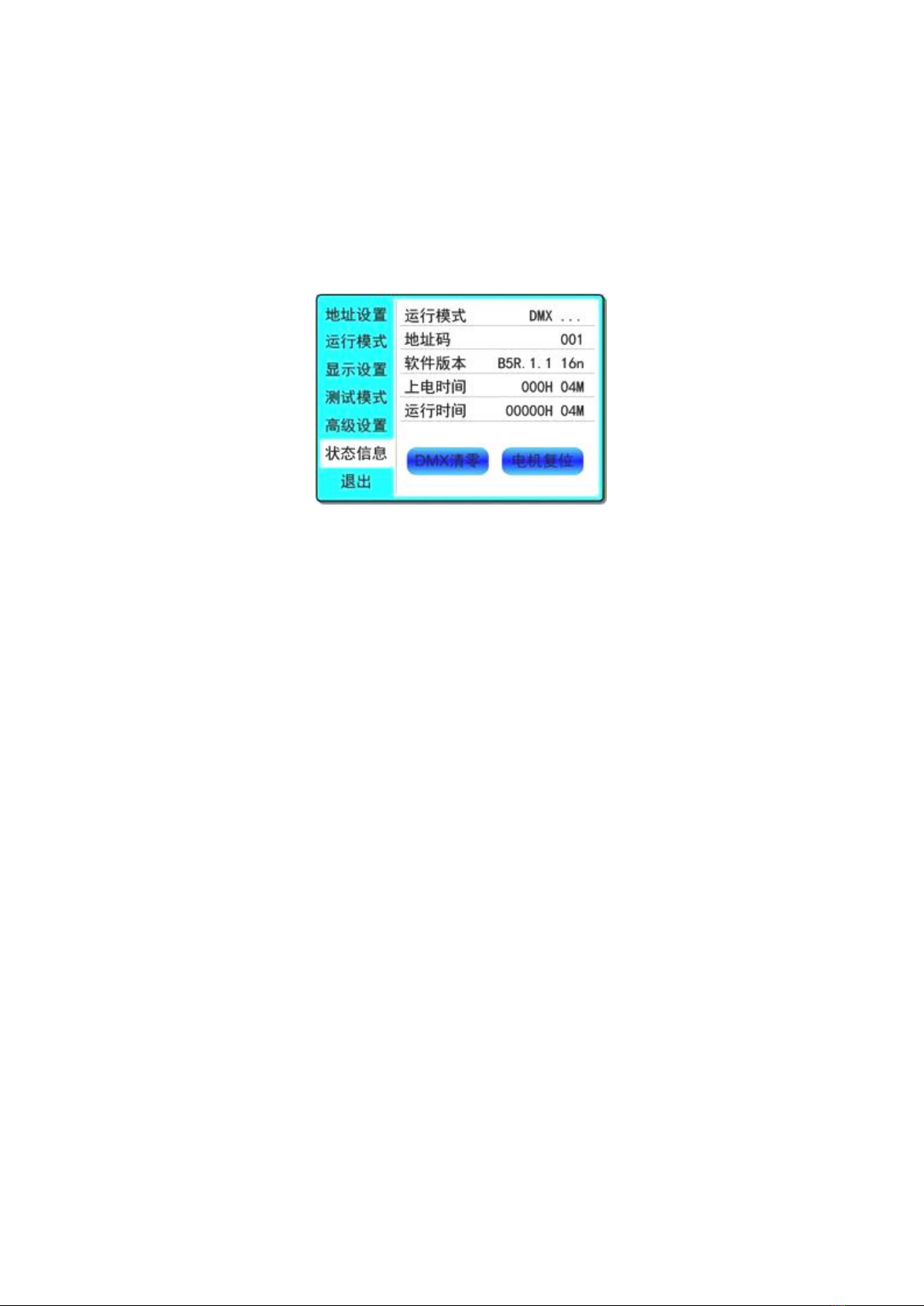
6. Check the current status of lamps6. Check the current status of lamps
Enter the page shown in Figure 12:
In this interface, you can view the operation status of the current lamp and the
version information of the lamp;
DMX clear (dmxclr): clear the DMX data;
Motor reset (sysrst): system reset button;
chart12 Status information page

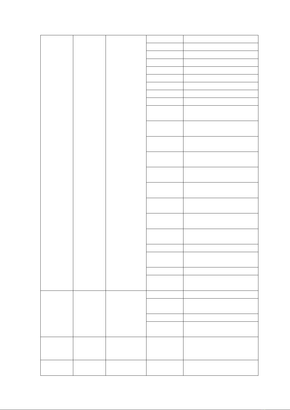
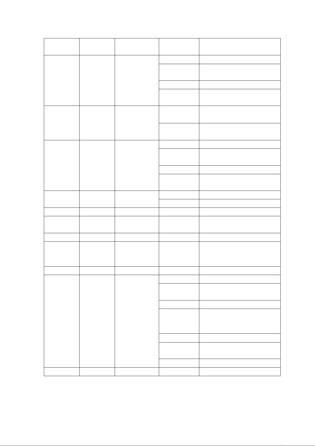
Chapter 3 channel description
1. Channel table1. Channel table
Watch1 Channel description (v1.10)
Channel 1
Channel 2
name
numerical
value
describe
CH1
CH1
X axis
0-255
0-540degree
CH2
X-axis trim
0-255
0-2degree
CH3
CH2
Y axis
0-255
0-270degree
CH4
Y-axis trim
0-255
0-1degree
CH5
CH3
XY speed
0-255
From fast to slow
CH6
CH4
function
30-50
3Full power after seconds
60-80
3Second half power
100-105
3Turn off the light gun
for more than seconds
200-205
3Turn on the light gun for
more than seconds
240-255
3Reset for more than
seconds
CH7
CH5
colour
0-129
Linear color matching
130-134
Color 1
135-138
Color 2
139-143
Color 3
144-147
Color 4
148-152
Color 5
153-157
Color 6
158-161
Color 7
162-166
Color 8
167-171
Color 9
172-176
Color 10
177-180
Color 11
181-185
Color 12
186-189
Color 13
190-220
From fast to slow forward
flow
221-224
stop it
225-255
Reverse flow from slow to
fast
CH8
Color tuning
0-255
Ch7 enabled when dimming
linearly
CH9
CH6
pattern
0-3
white light
4-9
Pattern 1
10-15
Pattern 2

16-21
Pattern 3
22-27
Pattern 4
28-33
Pattern 5
34-39
Pattern 6
40-45
Pattern 7
46-51
Pattern 8
52-57
Pattern 9
58-63
Pattern 10
64-69
Pattern 11
70-75
Pattern 12
76-81
Pattern 13
82-87
Pattern 14
88-95
Shake pattern 1 from slow
to fast
96-103
Shake pattern 2 from slow
to fast
104-111
Shake pattern 3 from slow
to fast
112-119
Shake pattern from slow
to fast 4
120-127
Shake pattern from slow
to fast 5
128-135
Shake pattern from slow
to fast 6
136-143
Shake pattern from slow
to fast 7
144-151
Shake pattern from slow
to fast 8
152-159
Shake pattern from slow
to fast 9
160-167
Shake pattern 10 from
slow to fast
168-175
Shake pattern 11 from
slow to fast
176-183
Shake pattern 12 from
slow to fast
184-199
Shake pattern 13 from
slow to fast
200-201
white light
202-227
From fast to slow forward
flow
228-229
stop it
230-255
Reverse flow from slow to
fast
CH10
CH7
Rotation
0-4
white light
pattern
5-8
Pattern 1
9-12
Pattern 2
13-16
Pattern 3
17-20
Pattern 4
21-24
Pattern 5
25-28
Pattern 6
29-32
Pattern 7
33-36
Pattern 8
37-40
Pattern 9
41-48
Shake pattern 1 from slow
to fast
49-56
Shake pattern 2 from slow
to fast
57-64
Shake pattern 3 from slow
to fast
65-72
Shake pattern from slow
to fast 4
73-80
Shake pattern from slow
to fast 5
81-88
Shake pattern from slow
to fast 6
89-96
Shake pattern from slow
to fast 7
97-104
Shake pattern from slow
to fast 8
105-112
Shake pattern from slow
to fast 9
113-119
white light
120-185
From fast to slow forward
flow
186-189
stop it
190-255
Reverse flow from slow to
fast
CH11
CH8
Gobo
Rotation
0-127
0-400degree
128-190
From fast to slow forward
flow
191-192
stop it
193-255
Reverse flow from slow to
fast
CH12
Rotation
fine
adjustment
0-255
CH13
CH19
Prism 1
0-63
Remove the prism
64-255
Insert prism 2
CH14
CH10
Prism 1
rotation
0-127
0-400degree
128-190
From fast to slow forward
flow
191-192
stop it
193-255
Reverse flow from slow to
fast
CH15
CH11
Prism 1
0-63
Remove the prism
64-255
Insert prism 2
CH16
CH12
Prism 2
rotation
0-127
0-400degree
128-190
From fast to slow forward
flow
191-192
stop it
193-255
Reverse flow from slow to
fast
CH17
CH13
atomization
0-127
nothing
128-255
atomization
CH18
CH14
enlarge
0-255
From small to large
CH19
Zoom in and
fine tune
CH20
CH15
focusing
0-255
From far to near
CH21
Focusing
fine
adjustment
CH22
empty
CH23
CH16
Stroboscopic
0-3
Guan Guang
4-103
From slow to fast pulse
stroboscopic
104-107
Open light
108-207
Gradually variable
frequency flashing from
slow to fast
208-212
Open light
213-251
Random stroboscopic from
slow to fast
252-255
Open light
CH24
CH17
Dimming
0-255
0-100% dimming

Chapter 4 common faults and precautions
1. Common fault handling1. Common fault handling
The lamp contains professional components such as microcomputer circuit
board and high-voltage power supply. For your safety and product life, non
professionals are not allowed to disassemble the lamp and related accessories
without authorization.
1. The bulb doesn't work
Possible causes: the bulb is not completely cooled, or the bulb has
reached its service life. The treatment is as follows:
If the bulb is not completely cooled due to abnormal operation, the lamp
body shall be cooled for more than 10 minutes to completely return to
the normal state, and then start the power supply again;
Check whether the bulb has reached its service life and replace it with
a new one;
Check whether there is leakage, falling off or poor contact between the
bulb and the lighter circuit;
Replace the lamp with a new one.
2. The beam looks dim
Possible causes: the bulb has been used for a long time or the optical
path is not clean. The treatment is as follows:
Check whether the bulb has reached its service life and replace it with
a new one;
Check whether the optical components or bulbs are clean and whether there
is dust accumulated on the bulbs and other optical components. The bulbs
and components in the lamps shall be cleaned and maintained regularly.
3. Pattern projection blur
Check whether the value of the electronic focus channel is appropriate for
the current projection distance.
4. Lamps operate intermittently
Possible causes: the internal circuit enters the protection state, and
the treatment is as follows:
Check whether the fan operates normally or becomes dirty, resulting in an
increase in the internal temperature of the lamp;
Check whether the internal temperature control switch is closed;

Check whether the bulb has reached its service life and replace it with
a new one.
5. The lamps will not be controlled by the console after normal reset
Possible causes: signal line failure or abnormal lamp parameter setting,
the treatment is as follows:
Check the start address code and the connection of DMX signal line (whether
the signal line cable is intact and whether the connector is loose);
Add signal amplifier and 120 ohm terminal resistance;
6. The lamp cannot be started
Possible causes: the power circuit is poor, and the treatment is as
follows:
Check whether the fuse on the power input socket is blown and replace the
fuse;
Poor line contact caused by vibration of lamps during long-distance
transportation
Check the input power supply, computer board and other plug-in devices.
2. Precautions for use2. Precautions for use
Check whether the local power supply meets the rated voltage requirements
of the product, and the leakage protector and overcurrent protector meet
the load requirements;
Do not use the power cord with damaged insulation, and do not lap the power
cord on other conductors;
The lamps are cooled by strong wind, which is easy to accumulate dust. They
must be cleaned once a month, especially the heat dissipation outlet,
otherwise they will be blocked by accumulated dust, resulting in poor
heat dissipation and abnormal lamps.
When installing lamps, the fixing screws must be fastened, equipped with
safety ropes, and checked regularly;
During the installation and positioning of lamps, the minimum distance
between any point on the surface of lamps and any inflammable and
explosive objects shall be 10m and 2.5m from the irradiated objects.
Please do not install lamps directly on the surface of combustible
substances;
It is recommended that the continuous working time of lamps should not
exceed 10 hours, and the interval between continuous starting lamps
should not be less than 10 minutes, otherwise it will not be triggered
normally due to bulb overheating protection;

The closing time of the on-off valve shall not exceed 5 minutes. If it is
necessary to close the light for a long time, the control console (lamp
control channel) shall be used to close the lamp;
In order to ensure that multiple lamps can better comply with the scene
effect, the lamps should not be in the current scene without completing
the current scene, that is, start the next scene action. It is best that
this state should not exceed 3 minutes to ensure that multiple lamps can
operate synchronously.
In the process of use, if the lamp is abnormal, stop using the lamp in time
to prevent inducing other faults;
Table of contents


