Shaw Satellite Antenna User manual

Satellite
Self-Installation
Manual
July 2014

1. Getting Started
This Shaw Direct Installation Manual provides all of the information required to setup your satellite
system. The manual provides step-by-step instructions, however skills in construction, wiring and
assembly will also be required to successfully complete the installation.
Self-Installation Explained:
Self-Installation of your Shaw Direct system can be broken down into three (3) basic steps:
1. Dish Assembly consists of assembling the pieces provided to form a complete satellite dish.
2. Dish Installation involves location suitable mounting locations, finding the satellite in relation
to your surroundings, and physically attaching the dish to your structure.
3. Connecting the Receiver consists of connecting your Shaw Direct satellite receive to the dish,
tuning to the correct channel, and fine-tuning the dish based on the satellite signal readings
provided.
IMPORTANT: We do not recommend installing the satellite dish on your roof, unless absolutely necessary. If
you choose to mount the dish on the roof, we strongly recommend consulting a building or construction expert
before installation.
IMPORTANT: Read this manual thoroughly before you start.
WARNING: All satellite dish systems must be properly grounded. Improper grounding can result in damage,
serious personal injury, and/or system performance issues. National, provincial and local electrical codes may
require you to ground the dish directly and to insert a grounding block in the coaxial cables running from the
dish to the receiver inside the building. Before beginning installation, carefully read the section on grounding
the dish (see section 10).
This installation requires you to:
•Use hand tools such as a drill
•Determine whether water pipes, electrical wiring or gas lines are close to the installation area
•Route coaxial cable through walls and under floors
•Use a compass, protractor and carpenter’s level
•Use a ladder to climb structures
•Know your local, provincial and national grounding codes
If you do not have the experience to perform these tasks, contact Shaw Direct for assistance.
1

You will need the following tools:
•Philips screwdriver
•3/8” hex or flat-head screwdriver
•7/16 hex wrench, open or combination end
•Electric drill and bits
•Carpenter’s level
•Compass
•Protractor
If you are installing a 75 cm dish, you will also require:
•2 - 13 mm wrenches (one to hold and one to tighten)
NOTE:You must use the mast that came with the dish, unless you are using a tripod.
Dish Kit Contents
75 cm
Elliptical
Dish
75E xKu
LNB
Clamp Mount Assembly
Hardware (see below)
Satellite Feed Support Arm
2” diameter
Universal Mount Assembly
75 cm Dish Kit
60 cm Elliptical Dish
60E xKu LNB
Clamp Mount Assembly
Hardware (see below)
Satellite Feed Support Arm
1¾ ” diameter
Universal Mount Assembly
60 cm Dish Kit
2

To facilitate assembly of the dish, arrange the hardware as follows. The number corresponds to the
steps listed in Section 3.
Missing pieces?
The Shaw Direct Self Install Kit contains many additional pieces to help you complete your
installation, including:
•Screws to attach the Universal Mount to
your structure
•Enough coaxial cable for two lines
•Dual grounding block and ground wire
•Dual coax wallplate
•Silicone to seal the cable entry holes and
dish mount holes
•A compass to help locate the satellite
•Hardware to route and secure the coaxial
cables, including zip ties and cable clips.
Give us a call at 1.888.554.7827 for more information or to purchase a Self Install Kit.
2a
2b
1
3
4
60 cm Hardware
5
2a
2b
1
3
4
75 cm Hardware
3

Helpful Hints
Key points to remember when installing your Shaw Direct System:
•Do not drill any holes until you’ve confirmed the best location for the dish.
•Make sure the installation of the dish conforms to local electrical and building codes, zoning
requirements and other applicable laws and regulations. If you are unsure, contact a local
electrician or building inspector for assistance.
•For possible periodic removal of snow, choose a site that is easily accessible.
•Ensure there are no visible obstructions between the dish and your line of sight to the
satellites. Keep in mind that trees will grow up and outward and may eventually block the
signal.
•The maximum allowable length for the RG-6 coaxial cable connecting the receiver to your
dish is 150 feet. Consult Shaw Direct if the cable will exceed this length.
•Use only RG-6 grade coaxial cable. Using lower grade RG-59 coaxial cable may result in
excessive signal loss and poor reception. Cable grade type is indicated on the outer jacket of
the cable.
Do not install the dish:
•Under power lines
•Where it may be easily tampered with
•Where it is exposed to high winds, during windy or stormy conditions
2. Mounting Locations
Your dish must be mounted on a solid base. To ensure your dish doesn’t move in windy conditions,
choose a location where it can be securely fastened. The mounting surface should be rigid and solid.
IMPORTANT: The Elliptical Dish has a turn radius of +/- 35 degrees. If you are mounting the dish on the side of
your house, check the assembled dish and mounting pole to see if you can rotate the dish in the desired
azimuth setting.
If you can’t rotate the dish, choose an alternate location.
Key things to remember when choosing a mounting location:
•The mounting surface should be flat, even and in good condition.
•If you install the dish on the roof or side of your house, be sure to attach the bolts into a
building stud, rafter or other solid surface.
•When mounting on the roof of your house, use an adequate/approved sealant (for your type
of roofing material) around the holes where the base of the universal mount meets the
mounting surface. This will prevent the roof from leaking. Consult with a roofing expert to
confirm best sealant.
4

We do not recommend:
•Mounting the dish on a railing or fence
•Installing the dish on aluminum or vinyl siding (these are unlikely to be structurally sound)
•Mounting the dish on the roof unless absolutely necessary.
Keep grounding requirements in mind (see section 10 for additional information on grounding).
3. Dish Assembly
60cm Dish
Step 1 – Assemble Universal Mount
Assembly
NOTE: This step is not required if you will be
installing your dish on a tripod.
Insert the ½" Carriage Head bolt (1) as shown
in FIGURE A-60, and secure it with a lock nut
(2). Repeat for the opposite side. Tighten
just enough to hold in place.
Step 2 – Assemble Clamp Mount Assembly
(FIGURE B-60)
a. Azimuth Adjustment
Insert the two ¾" Carriage Head
bolts in the top of the Clamp
Mount Assembly. Insert a
washer and lock nut on each
bolt. Tighten just enough to hold
in place.
b. Elevation Adjustment
Insert the 3/8" Carriage Head
bolts in the elevation adjustment
area. Insert a lock nut on each
bolt. Tighten just enough to hold
in place.
FIGURE A-60
1
2
Universal
Mount
Universal
Mount
Assembly
FIGURE B-60
Azimuth
Adjustment
Elevation
Adjustment
1
2a
2b
5

Step 3 – Attach the Clamp Mount
Assembly to the 60 cm Elliptical Dish
(FIGURE C-60)
Place the completed Clamp Mount
Assembly on the back of the 60cm Elliptical
dish. When looking at the back of the dish,
the marked skew adjustment scale should
be on the left.
Insert the two longest (painted head)
carriage head bolts (1) through the two
holes on the front of the dish.
Secure each bolt with a flat washer (2) and
a lock nut (3). Tighten just enough to hold
in place – these will be used for Skew Adjustment.
Step 4 – Attach the Satellite Feed Support Arm to the
60 cm Elliptical Dish
Attach the Satellite Feed Support Arm to the 60 cm
Elliptical Dish using the remaining hex head bolt (1), flat
washer (2), plastic spacer (3), and lock nut (4), as shown
in FIGURE F-60. Ensure the slot at the opposite end is on
the underside of the feed support arm. Tighten fully.
Do not attach the LNB to the Satellite Feed Support Arm
just yet. This will be done later.
Step 5 – Secure the clamp mount assembly to the 60 cm Elliptical Dish
You will use the two remaining hex head Hi/Lo screws in Step 9 on page 11.Do not insert them yet.
3
4
FIGURE C-60
2
Flat
Washer
1
Carriage Head Bolt
(painted head)
Dish socket
(bottom of dish)
Clamp
Mount
Assembly
Centre Pivot Pin
3
Lock
Nut
FIGURE F-60
3
Plastic
Spacer
1Hex Head Bolt
Feed Support Arm
2
Flat
Washer
Dish socket
(bottom of dish)
4
Lock
Nut
5
6

75cm Dish
Step 1 – Assemble Universal Mount
Assembly
NOTE: This step is not required if you will be
installing your dish on a tripod.
Insert the smallest Carriage Head bolt (1) as
shown in FIGURE A-75, followed by the star
washer (2), regular flat washer (3), and lock nut
(4). Repeat for the opposite side. Tighten just
enough to hold in place.
Step 2 – Assemble Clamp Mount
Assembly (FIGURE B-75)
c. Azimuth Adjustment
Insert the two largest Carriage
Head bolts in the top of the Clamp
Mount Assembly. Insert a washer
and lock nut on each bolt. Tighten
just enough to hold in place.
d. Elevation Adjustment
Insert the remaining Carriage Head
bolts in the elevation adjustment
area. Insert a washer and lock nut
on each bolt. Tighten just enough
to hold in place.
Step 3 – Attach the Clamp Mount
Assembly to the 75 cm Elliptical Dish
(FIGURE C-75)
Place the completed Clamp Mount
Assembly on the back of the 75cm
Elliptical dish. Insert the two longer
Plow Bolts through the top holes on the
front of the dish. Insert the two shorter
Plow Bolts through the lower holes on
the front of the dish.
FIGURE A-75
1
2
3
4
FIGURE B-75
Azimuth
Adjustment
Elevation
Adjustment
1
2a
2b
FIGURE C-75
3
7

Secure each bolt with a skew lock clip, lock washer, and hex nut. Tighten just enough to hold in
place – these will be used for Skew Adjustment.
Step 4 – Attach the Satellite Feed Support Arm to the 75 cm
Elliptical Dish
Attach the Satellite Feed Support Arm to the 75 cm Elliptical Dish
using the remaining bolt, plastic spacer, flat washer, and hex nut, as
shown in FIGURE F-75.Ensure the slot at the opposite end is on the
underside of the feed support arm. Tighten fully.
Do not attach the LNB to the Satellite Feed Support Arm just yet.
This will be done later.
4. Locating the Satellites
Step 1: Determine the direction in which to point the dish. The first two satellites (SAT A) are located
at 107.3 west longitude; the other satellite (SAT B) is located at 111.1 west longitude. Your xKu LNB
and elliptical dish will be aimed to receive signal from all three satellites.
IMPORTANT: Always use the SAT B Azimuth, Elevation and Skew listings in the Satellite Locator Chart at the
back of this manual for the city nearest your location. This will ensure alignment to all three satellites.
Write them here:
Azimuth
Elevation
Skew
SAT A: ______________________
SAT B: ______________________
You will adjust the dish as follows to set the azimuth, elevation, and skew:
FIGURE F-75
Support
Arm Spacer
4
Azimuth
Elevation
Skew
8

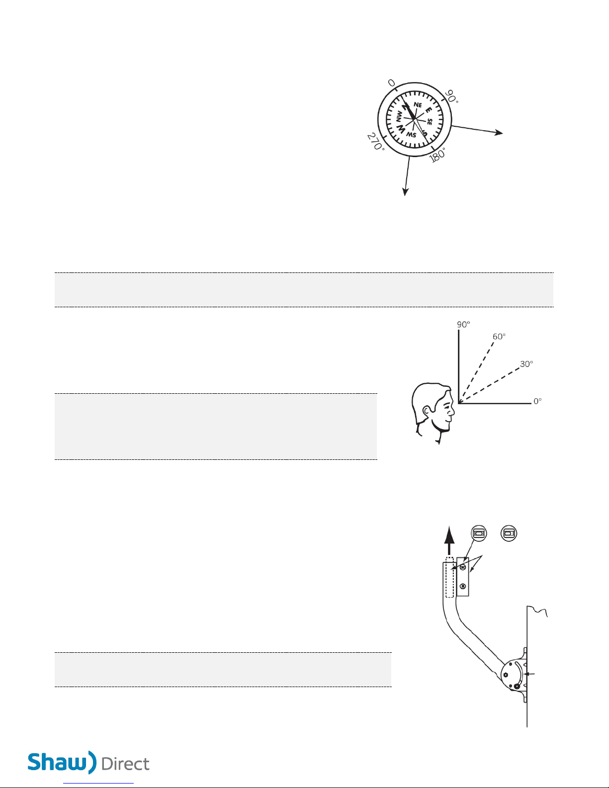
Step 2: At the dish install site, hold a compass
level and still in the palm of your hand. When the
needle stops rotating (dark half of the needle
always points north), slowly rotate the body of
the compass so that the “N˝ marking is aligned
with the dark half of the needle. Locate the tick
mark on the compass edge corresponding to the
SAT B azimuth number you wrote down earlier
(see Figure G). This is the direction in which to
point your dish to receive both SAT A and SAT B
signals.
TIP: Use a stick or other object to mark the correct azimuth direction.
NOTE: To ensure an accurate compass reading, stay away from large metal objects. To double-check accuracy,
take multiple readings several feet apart.
Step 3: Estimate the SAT B elevation (angle) setting you
recorded earlier, using a protractor if needed (see Figure H).
Check any obstructions at that elevation. If there are
obstructions, then select an alternate location for the dish.
IMPORTANT: When evaluating the install location, make sure there are
no trees, branches or objects visually obstructing the dish and the
general direction of the satellite. Also, keep in mind that trees grow up
and outward and may eventually block the signal.
You have just completed locating a site for your dish.
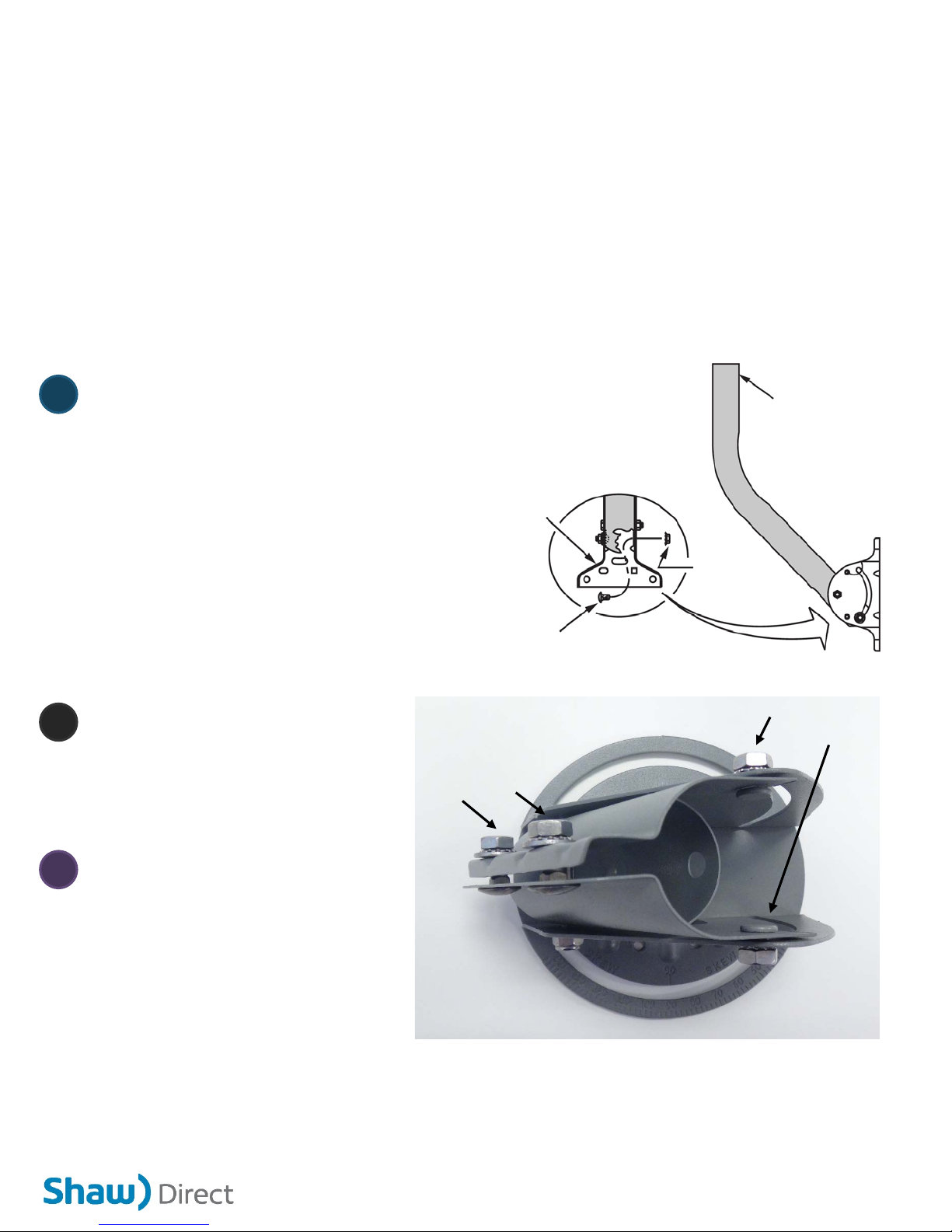
5. Attaching the Dish
Step 1: Ensure mast is plumb before drilling any holes. Hold the
Universal Mount in place on the mounting area. Use a carpenter’s
level to plumb the antenna mast’s straight section. If the bubble
levels (horizontal and vertical) are not centered, rotate the mast (in
the curved slot) until it is plumb. Lock it in place by securely
tightening the Mast Adjusting Bolts (see Figure I).
IMPORTANT: Alignment of the dish will be difficult if the mast is not
plumb.
Step 2: Drill holes in the structure on which you are mounting the
dish to match the holes in the base of the Universal Mount.
FIGURE G
If you live in Newfoundland, the
satellite will be to the Southwest.
If you live in
Vancouver, the
satellite will be
to the
Southeast.
FIGURE H
0 degrees is straight
toward the horizon and 90
degrees is straight upward.
FIGURE I
Level Not Level
Use bubble level to
plumb mast so it is
vertical in all
directions.
9

Step 3: Secure the Universal Mount with appropriate surface screws. Check the mount for
movement. An improperly secured mount will affect signal reception.
Step 4: Slide the Dish/Clamp Mount Assembly onto the mast by loosening the (2) Azimuth Clamp
Bolts (see Figure B) and the Elevation Pivot Bolt just enough to slide the assembly until it makes
contact with the Elevation Pivot Bolt (see Figure J). Tighten the Elevation Pivot Bolt just enough to
hold it in place on the mast.
Step 5: Loosen the Elevation Adjustment Bolt 1/3 turn from tight on either side of the Clamp Mount
Assembly. Adjust the Clamp Mount Assembly to the edge of the white indicator line per the SAT B
elevation setting you recorded earlier. Tighten the Elevation Adjustment Bolts (see Figure J).
Step 6: Attach the xKu LNB/Feedhorn Clamp Assembly to the Feed Support Arm. Loosen the Feed
Arm screw enough to allow the clamp to fit snugly into the Feed Support Arm. Securely tighten the
Feed Arm screw.
Step 7: Using your compass, point the LNB in the direction
corresponding to the SAT B azimuth setting (see Figure K).
Draw a vertical mark overlapping the Clamp Mount
Assembly and the mast. This mark will provide you with the
approximate satellite location reference point when you are
ready to tune to the satellite.
Step 8: Loosen the Skew Adjustment Bolts on either side of
the Clamp Mount Assembly. Adjust the Skew Alignment Mark with the scale indicator to the SAT B
skew setting you recorded earlier. Finally, lock it in place by securely tightening the Skew Adjustment
Bolts.
IMPORTANT: Do not make any further adjustments to the Skew Setting from this point onward.
FIGURE J
Use the metal edge, not the nut, to set elevation.
(Example: In this picture, the elevation is set at 26.)
When adjusting elevation, use the
edge of the metal to line up with the
elevation setting for your area on the
elevation scale.
Elevation
Indicator
Elevation Pivot Bolt
Elevation
Adjustment
Bolt
FIGURE K
10

Step 9: If you are installing a 60 cm dish, install
the two remaining Hi/Lo hex head screws in
the dish boss holes, shown in Figure L-60. Four
boss holes are available but you'll only need to
use two (the other two may be obstructed
depending on the skew setting). Do not over
tighten the hex head screws.
You have just finished attaching the Dish to the
Universal Mount.
6. Connecting the Receiver and Dish
You are now at the point in the installation
where one of the output ports of the xKu LNB needs to be connected to the Shaw Direct satellite
receiver. Connect the receiver to a TV to see a relative scaled signal level meter that will assist you in
obtaining maximum signal strength. If you are unsure of how to connect the TV to the receiver, refer
to the User Guide that came with your receiver.
NOTE: The following instructions apply to the HDDSR 600, HDDSR 605, and/or HDPVR 630 receiver. If you have
a different model satellite receiver, instructions may vary.
Step 1: Connect the RG-6 coaxial cable provided with the install kit to one of the ports of the xKu
LNB. Connect the other end of the coaxial cable to the satellite receiver input connector (If you are
using an HDPVR 630, you must connect two coaxial cables). To make the dish alignment easier, we
suggest you temporarily locate the receiver and TV at an electrical outlet close to where the dish is
installed. Unless you can view the signal level on the TV screen from where the dish is being aligned,
you will require an assistant to monitor the signal level reading on the TV as you align the dish.
Step 2: Tune your satellite receiver to the correct channel to be able to receive signal:
•If your receiver has never been activated or has been provided as a warranty replacement, it
will be on channel 299. Tune to channel 252.
•If your receiver has been previous activated, tune to channel 700.
•If you are using an HDPVR 630 which has never been activated or has been provided as a
warranty replacement, tune to channel 250, and then 252.
•If you are using an HDPVR 630 which has been activated previously, tune to channel 711, and
then 700.
FIGURE L-60
Boss Holes
Boss Holes
11

Step 3: Access the Tune in Satellite Signal menu. To access this menu, press OPTIONS on the
remote, followed by the numbers 4, 3, 1. Depending on which version of software is running on your
receiver, the menu will look like the one in
either figure M-1 or M-2
The Tune in satellite signal screen will
display the current signal on a scale of 0
(no signal) to 99 (maximum signal). The
objective is to maximize the signal, which
will typically reach up to 98 under ideal
conditions. It is not necessary to enter an
"EMM Provider ID".
You will hear an audio beeping that will
increase in speed as signal strength
increases and will become a monotone
once you have reached approximately 50%
signal strength.
IMPORTANT: The audio tone is not available if
your receiver is connected via HDMI.
Always press GO BACK on the remote to exit the
Tune in Satellite Signal screen to prevent loss of
audio when leaving this menu.
Step 4: Verify the connection between the
satellite receiver and the LNB. The square
next to the signal bar should be green. (For
HDPVR 630, both squares should be green).
If the square is red, ensure the RG6 coaxial
cable is securely attached to the correct port on the back of the receiver, and one of the four ports on
the LNB. The square must be green before proceeding.
7. Aligning the Dish to Acquire Shaw Direct Signal
With the receiver on and your assistant ready to monitor signal strength on the TV, you are now
ready to make adjustments to the dish to acquire the Shaw Direct satellite signal. If you are using a
satellite finder, please refer to the instructions in Section 9.
Step 1: Refer to the azimuth, elevation and skew settings for the location that you recorded on Page
8.
FIGURE M-1 (SD Guide)
Signal
Strength
Signal
Square
FIGURE M-2 (HD Guide)
Signal
Strength
Signal
Square
12

Step 2: Check that the dish skew is set to
the skew setting listed for your area. The
skew alignment mark is shown in Figure N.
Step 3: Check that the dish elevation is set
to the elevation setting listed for your area.
Step 4: Draw a reference mark on the dish
clamp and pipe mast as a starting point
before you make any adjustments to the
dish.
Step 5: Standing behind the dish, using
both hands, grasp the dish on each side
and move it so that it points all the way
west. Then, slowly move the dish in very small increments to the east while your assistant observes
the TV installation menu for increases in signal strength.
Step 6: As you start to get an indication of increasing signal, make a second reference mark on the
dish clamp and pipe mast to serve as a point where signal strength increased.
Step 7: As you move the dish past the point of maximum signal strength, move the dish back in the
opposite direction until you achieve maximum signal.
Step 8: Tighten the dish clamp screws.
Step 9: Now make small adjustments to the elevation of the dish to see if you can further improve on
the signal strength. Loosen the Elevation Adjustment Bolts and make slight adjustments (1/2 degree
increments) in the elevation, finding the maximum signal strength. When you’ve located the
maximum signal strength possible, securely tighten all bolts.
NOTE: Do not be discouraged if you do not acquire signal on your first attempt. Be patient and try again.
Recheck the pipe mast for true vertical 90 degrees. Once you acquire signal, you may need to make very small
adjustments to the dish compass heading (azimuth), elevation and skew settings to maximize signal strength
above 80.
Authorizing Receiver for Service
If your receiver installer menu displays signal strength above 80, you have successfully aligned the
dish to the Shaw Direct satellite.
You are now ready to authorize your receiver for programming.
FIGURE N
Skew
Adjustment
Mark
Use the skew adjustment mark, not the nut, to set skew.
(Example: In this picture, the skew is set at 100.)
13

8. Activation and Fine Tuning
Step 1: Call Shaw Direct at 1.888.554.7827 to authorize your receiver for programming.
Shaw Direct will ensure the correct channel map is set for your receiver and verify the reception of
each satellite. After your receiver has been activated, you can fine tune the dish to ensure maximum
signal strength on all channels.
While speaking with the Shaw Direct representative, ask for a reference channel from each satellite
to use when fine tuning the dish.
Step 2: Tune to the first reference channel provided and access the Tune in Satellite Signal menu as
described in Section 6.
Fine tuning the Azimuth:
Step 3: With your assistant monitoring the signal level, move the dish back and forth slightly (about a
millimeter at a time) to attempt to acquire the highest reading possible on the signal strength meter.
Step 4: Once you have found the maximum signal strength, lock the azimuth rotation position in
place by tightening the Azimuth Clamp Bolts (see Figure B).
NOTE: Fine tuning to the highest signal strength possible reduces signal interference in adverse weather
conditions and ensures optimal reception from all satellites.
Fine tuning the Elevation:
Step 5: Loosen the Elevation Adjustment Bolts and make slight adjustments (1/2 degree increments)
in the elevation, finding the maximum signal strength, as you did in the azimuth tuning process.
Step 6: Exit the Tune in Satellite Signal menu and tune to the second reference channel provided. Go
back into the Tune in Satellite Signal menu and repeat steps 3-5 to maximize signal strength from
the second satellite. (If your receiver is running the HD Guide, it is not necessary to exit the screen –
you can change channels from within the Tune In Satellite Signal menu.)
Step 7: When you’ve located the highest signal possible on both channels, securely tighten all bolts.
YOU HAVE JUST COMPLETED FINE TUNING. Skip ahead to section 10.
14

9. Alternate Tuning Method
You may prefer to locate the satellites using a SF-100 Satellite
Finder (see Figure O), a standalone satellite signal finding meter
which can be purchased separately from Shaw Direct or your Shaw
Direct retailer.
Step 1: Connect a short coaxial cable from the LNB terminal on the
Satellite Finder to the xKu LNB. Connect the receiver terminal on
the meter to a coaxial cable, which in turn connects to the SAT IN
port on the Shaw Direct receiver.
Step 2: Tune to the channel advised in Section 6.
NOTE:For the satellite finder and LNB to function, they must be connected to a satellite receiver that is plugged
in and turned on.
Step 3: Adjust the dish as closely as possible to the elevation and azimuth settings you recorded
earlier.
Step 4: Move the dish azimuth rotation very slightly to the right of the reference mark you drew on
page 8.
Step 5: Slowly rotate the dish back toward the reference mark and listen for pitch changes in the
audible tone. If your elevation is set correctly, you should hear two major pitch changes as it picks up
the satellite signals. A weak first change of pitch may be the wrong satellite. Continue rotating the
dish until the second major deflection, which will be SAT A (107.3), your intended target.
Step 6: When you have located both signals, move the dish slightly to the right and left of the mark
until you’ve maximized the signal. Then tighten the Azimuth Clamp Bolts. Verify you’ve located the
correct satellite by confirming signal strength on the satellite receiver (see page 12).
Step 7: While listening to the meter, apply gentle pressure to the top of the dish to move the dish –
first slightly downward, then upward to see if you can increase the signal strength further. Carefully
adjust the elevation until you’ve maximized the signal. Tighten the Elevation Adjustment Bolts.
Step 8: Follow the steps described in Fine Tuning (Section 8) to obtain the highest reading possible
on the signal strength meter.
Step 9: The dish should now be peaked to its maximum. Remove the Satellite Finder and plug the
LNB directly into the receiver. Confirm the signal strength by checking the on-screen signal strength
meter, as described in Section 6.
Your system is now fine tuned.
FIGURE O
15

10. Grounding the Coaxial Cable
The Shaw Direct Self Install kit includes the following items to ground
the outdoor coaxial cable:
•Dual Coax Cable Grounding Block
•Grounding Wire
Outdoor coaxial cable that may be subject to static discharge or
contact with electrical wiring must be grounded through a grounding
block located as close as possible to the cable entry point (see Figure
P).
Step 1: Attach the grounding block to the side of your home, close to
the coaxial cable entry point. Connect the coaxial cable(s) running
from the dish, and to the receiver(s).
Step 2: Attach the ground wire to the grounding block connector and
tighten the screw.
Step 3: Attach the grounding wire from the
grounding block connector to the central building
ground or another approved grounding point.
Acceptable grounding points may include a ground
rod, metal electrical service panel, or copper cold
water pipe within five feet of the entrance to the
structure. Examples are shown in Figure Q.
IMPORTANT: Always refer to your regional electrical
code and/or contact a licensed electrician if you are
unsure about your local grounding requirements.
IMPORTANT: For more information on grounding, refer to
the receiver’s User Guide included with your Shaw Direct
system.
11. Troubleshooting
If you are having trouble finding the satellite signal, try each of the following:
•You must be tuned to a valid channel in order to align the dish. Review section 6 for the
channels to use with the xKu LNB. If you do not have an xKu LNB, try aligning the dish on
channel 299.
FIGURE P
Grounding
Block
FIGURE Q
Grounding
Block
Grounding
Wire
Grounding
Location
16

•The cable can be plugged into any of the four (4) available ports on the xKu LNB, but must be
plugged into the SAT IN port on the Shaw Direct receiver. If you have an HDPVR 630, two (2)
cables must be connected to the SAT 1 and SAT 2 ports.
•Make sure all cables are secure and re-verify your azimuth, elevation and skew setting for
your location. The settings straight section must be plumb.
•Adjust the elevation by +1 degree from the settings you recorder earlier and repeat the steps
in Section 7 to acquire Shaw Direct signal.
•Adjust the elevation by –1 degree from your original settings you recorded earlier and repeat
the steps in Section 7 to acquire Shaw Direct signal.
•Ensure cables are connected properly at the grounding block.
If you still can’t select or acquire signal, call us at 1.888.554.7827 for further assistance.
12. Satellite Locator Chart
Satellite coordinates are provided on the next page for both Satellite A (107.3W longitude) and
Satellite B (111.1W longitude.) The reception of satellite signals in areas with a dish elevation less
than 12 degrees may not be possible. Consult with a Shaw Direct retailer in your area. All
information is listed in degrees.
Note: Please refer to the SATELLITE B settings if you have an elliptical dish. Satellite A should only be used for
a round dish.
Online Satellite Location
If you have access to a computer, exact dish coordinates can also be obtained at
www.dishpointer.com. Enter your current address and then select “111.1W ANIK F2” as the satellite.
For the “LNB Skew” listed online, add 90 degrees for equivalent settings. For example, an LNB skew
listed online as “-5.0°” is 85 degrees. An LNB skew listed online as “30.0°” is 120 degrees.
17

Satellite A
Satellite B
Compass
Azimuth
Dish
Elevation
Dish
Skew
Compass
Azimuth
Dish
Elevation
Dish
Skew
Azimut –
Coord.
magn.
Élévation
Inclin-
aison
Azimut –
Coord.
magn.
Élévation
Inclin-
aison
Newfoundland /Terre-Neuve
Bonavista
264
14.4
126
267
12.1
127
Cartwright
262
13.8
120
265
11.9
121
Corner Brook
260
17
124
263
14.8
125
Gander
263
15
125
266
12.8
126
Grand Falls
262
15.7
125
265
13.5
126
Hebron
259
13.6
114
262
12
115
Indian Harbour
262
13.6
119
265
11.7
120
Labrador City
251
19.1
116
254
17.3
118
Nain
258
14.4
116
262
12.7
117
North West River
259
15.5
119
262
13.6
120
Nutak
259
13.8
115
262
12.2
116
Placentia
263
15.5
127
266
13.2
128
Port aux Basques
258
18.5
125
262
16.2
126
Rigolet
261
14.3
119
264
12.4
120
Schefferville
251
17.8
115
255
16.1
116
St. Anthony
262
14.4
122
266
12.3
124
St. John’s
264
14.6
127
267
12.3
128
Trepassey
263
15.4
128
267
13.1
129
Wabush City
251
19
116
254
17.2
118
Nova Scotia / Nouvelle-Écosse
Bridgewater
252
23.7
125
256
21.3
127
Cape Breton Is.
256
20.5
125
260
18.2
127
Chesterfield In.
208
17.5
98
212
16.9
100
Dartmouth
254
22.9
125
257
20.6
127
Freeport
250
24.8
124
254
22.5
126
Mulgrave
256
21
125
259
18.6
127
Port Hawkesbury
256
21
125
260
18.6
127
Port Maitland
250
24.9
125
254
22.5
127
Sable Is.
258
21.1
128
261
18.6
129
Shelburne
251
24.6
125
255
22.2
127
Sydney
257
19.9
125
261
17.6
127
Truro
254
22.3
125
257
20
126
Wedgeport
250
25
125
254
22.6
127
Yarmouth
250
25
125
254
22.7
127
Prince Edward Island / Ile-du-Prince-Édouard
Charlottetown
254
21.7
124
258
19.4
126
New Brunswick / Nouveau-Brunswick
Bath
248
24
122
252
21.9
123
Bathurst
251
22.2
122
255
20.1
123
Chatham
251
22.5
122
255
20.3
124
Dalhousie
250
22.3
121
254
20.2
123
Edmundston
247
23.8
120
251
21.7
122
Fredericton
250
23.9
123
253
21.7
124
Grand Manan Is.
249
24.9
124
253
22.6
126
Hartland
248
24.1
122
252
22
124
Kedgwick
249
23.1
121
252
21
123
Moncton
252
22.7
123
256
20.5
125
Napadogan
249
23.8
122
253
21.6
124
Newcastle
251
22.6
122
255
20.4
124
Oromocto
250
23.9
123
253
21.6
125
Plaster Rock
249
23.6
121
252
21.5
123
St. John
250
24
123
254
21.7
125
Québec
Alma
242
24.7
118
246
22.7
120
Amos
231
27.6
114
235
25.9
116
Anticosti
254
19.6
121
258
17.5
123
Asbestos
242
26.9
120
246
24.9
122
Baie Comeau
248
22.4
119
251
20.4
121
Baie St.Paul
244
24.9
119
248
22.9
121
Asbestos
242
26.9
120
246
24.9
122
Satellite A
Satellite B
Compass
Azimuth
Dish
Elevation
Dish
Skew
Compass
Azimuth
Dish
Elevation
Dish
Skew
Azimut –
Coord.
magn.
Élévation
Inclin-
aison
Azimut –
Coord.
magn.
Élévation
Inclin-
aison
Beattyville
232
26.9
114
237
25.2
116
Cap-de- la-Madeleine
241
26.8
119
245
24.7
121
Charlesbourg
243
25.7
119
247
23.7
121
Chibougamau
238
24.9
115
242
23.1
117
Chicoutimi
243
24.4
118
247
22.5
120
Cowansville
240
27.8
120
244
25.7
122
Dolbeau
241
24.7
117
245
22.8
119
Donnacona
242
26.1
119
246
24.1
121
Dosquet
242
26.2
119
246
24.1
121
Drummondville
241
27.1
119
245
25.1
121
Eastmain
231
24.5
111
235
23
113
Festubert
240
26.2
118
244
24.2
120
Fort Coulonge
233
29.3
117
237
27.4
119
Gagnon
248
20.4
117
252
18.6
118
Gaspe
253
20.7
121
256
18.6
123
Gatineau
235
29.1
118
239
27.1
120
Granby
240
27.6
120
244
25.6
122
Grand Mere
241
25.1
117
245
23.2
119
Hauterive
248
22.5
119
251
20.5
121
Hull
235
29.1
118
239
27.2
120
Inukjuak
235
19
107
239
17.8
109
Ivujivik
240
15.4
105
244
14.4
106
Joliette
239
27.5
119
243
25.5
121
Kuujjuaq
252
15.8
112
256
14.4
113
Kuujjuarapik
234
21.5
109
238
20.1
111
La Sarre
228
27.8
113
233
26.2
115
La Tuque
240
26.1
118
244
24.1
120
Levis
243
25.7
119
247
23.7
121
Madeleine
256
20.1
124
259
17.8
125
Malartic
230
28
114
235
26.2
116
Maniwaki
235
28.5
117
239
26.6
119
Matagami
232
26.5
113
236
24.8
115
Matane
249
22.3
120
252
20.3
121
Mingan
253
19.5
120
257
17.5
122
Miquelon
234
26.2
114
238
24.5
116
Mistassini
241
24.6
117
245
22.8
119
Monet
235
26.8
115
239
25
118
Mont Laurier
235
28.1
117
239
26.2
119
Mont Louis
251
21.1
120
255
19.1
122
Montmagny
244
25.3
120
248
23.2
122
Montreal
239
28
119
243
26
121
Mont Joli
247
22.9
119
251
20.9
121
Natashquan
256
18.4
121
260
16.3
123
Noranda
229
28.2
113
233
26.5
116
Parent
237
26.6
116
241
24.7
119
Paspebiac
251
21.7
121
255
19.6
123
Pointe aux Anglais
249
21.6
119
253
19.6
121
Pointe-aux-Tremble
239
27.8
119
243
25.8
121
Port Cartier
250
21.2
119
253
19.2
121
Quaqtaq
253
14.1
109
256
12.8
110
Quebec
243
25.8
119
247
23.7
121
Rimouski
247
23.1
119
251
21.1
121
Riviere-du-Loup
245
24.1
119
249
22.1
121
RivierePentecote
249
21.5
119
253
19.5
121
Roberval
241
25
117
245
23.1
119
Rouyn
229
28.2
113
233
26.5
116
Salluit
244
15
106
248
14
107
Senneterre
232
27.3
114
236
25.6
117
Sept Iles
250
20.8
119
254
18.8
121
Shawinigan
240
26.7
119
244
24.7
121
Sheldrake
252
20
120
256
18
121
18

Satellite A
Satellite B
Compass
Azimuth
Dish
Elevation
Dish
Skew
Compass
Azimuth
Dish
Elevation
Dish
Skew
Azimut –
Coord.
magn.
Élévation
Inclin-
aison
Azimut –
Coord.
magn.
Élévation
Inclin-
aison
Sherbrooke
242
27.2
120
246
25.1
122
Sorel
240
27.3
119
244
25.3
121
St. Paul du Nord
246
23.5
119
250
21.5
121
St. Agathe-des-Monts
238
27.9
118
242
26
120
St. Agapit
242
26
119
246
24
121
St. Anne de Beaupre
243
25.5
119
247
23.4
121
St. Augustin
259
16.1
121
263
14.1
123
St. Boniface
188
32
99
193
31.3
102
St. Eloi
246
23.8
119
250
21.8
121
St. Hyacinthe
240
27.6
119
244
25.5
121
St. Jean
239
28
119
243
25.9
122
St. Jerome
238
28
118
242
26
121
St. Jean de Matha
239
27.4
118
243
25.4
121
St. Laurent
239
28
119
243
26
121
St. Pacome
245
24.7
119
249
22.6
121
St. Pascal
245
24.5
119
249
22.4
121
St. Simeon
245
24.3
119
249
22.3
121
St. Stephen
249
24.8
123
252
22.5
125
Tadoussac
245
24
119
249
22
121
Trois-Rivieres
241
26.8
119
245
24.8
121
Val d’Or
231
27.8
114
235
26.1
116
Valleyfield
238
28.5
119
242
26.4
121
Vandry
239
26.1
117
243
24.2
119
Verdun
239
28
119
243
26
121
Victoriaville
242
26.7
119
246
24.6
122
Waskaganish
230
25.3
111
234
23.8
113
Wemindji
231
24
110
235
22.5
112
Windsor
241
27.1
120
245
25
122
Ontario
Apsley
231
30.8
116
235
28.9
119
Arnprior
234
29.4
117
238
27.5
120
Bancroft
231
30.5
116
235
28.6
119
Barrie
227
31.9
116
232
30
118
Belleville
232
31
117
236
29
120
Blind River
220
31.6
112
225
30
115
Bracebridge
228
31.2
115
232
29.3
118
Bradford
228
32.1
116
232
30.2
119
Brampton
227
32.6
116
232
30.7
119
Brockville
235
29.8
118
239
27.8
121
Burlington
227
32.9
116
232
31
119
Carleton Place
234
29.6
117
238
27.6
120
Chapleau
220
30.4
110
224
28.9
113
Chatham
223
34.8
115
227
33
118
Cobalt
227
29.3
113
232
27.6
116
Cobourg
230
31.6
117
235
29.6
120
Cochrane
225
28.3
111
229
26.8
114
Collingwood
226
32.1
115
231
30.2
118
Cornwall
237
29
119
241
26.9
121
Dalton
218
30.3
110
223
28.8
112
Deep River
232
29.4
116
236
27.6
118
Dryden
198
31.1
102
203
30.3
105
Elliot Lake
221
31.3
112
226
29.7
115
Emsdale
228
30.7
115
232
28.9
118
English River
202
31.4
104
207
30.3
107
Espanola
223
31.2
113
227
29.5
115
Foleyet
222
29.8
111
226
28.2
114
Fort Albany
224
25.6
109
229
24.3
111
Fort Frances
197
32.6
102
202
31.6
105
Fort Severn
212
23.8
103
216
22.9
105
Gananoque
234
30.2
118
238
28.2
121
Geraldton
212
29.8
107
216
28.5
109
Satellite A
Satellite B
Compass
Azimuth
Dish
Elevation
Dish
Skew
Compass
Azimuth
Dish
Elevation
Dish
Skew
Azimut –
Coord.
magn.
Élévation
Inclin-
aison
Azimut –
Coord.
magn.
Élévation
Inclin-
aison
Gilmour
231
30.6
117
236
28.7
119
Goderich
223
33.4
115
228
31.6
117
Gogama
223
29.9
112
228
28.3
114
Gravenhurst
229
31.1
116
233
29.3
118
Guelph
226
32.9
116
231
31
119
Haliburton
231
30.6
116
235
28.7
119
Hamilton
227
33
116
232
31.1
119
Hanover
225
32.7
115
229
30.9
118
Hearst
219
28.7
109
224
27.3
112
Hornepayne
217
29.5
108
221
28.2
111
Huntsville
228
30.9
115
233
29.1
118
Ignace
201
31.4
103
205
30.3
106
Ingersoll
225
33.7
116
230
31.8
119
Iroquois Falls
225
28.4
112
230
26.9
114
Kapuskasing
222
28.5
110
226
27.1
113
Kenora
194
31.6
101
199
30.7
104
Kincardine
223
33
114
228
31.2
117
Kingston
234
30.5
118
238
28.5
121
Kirkland Lake
227
28.7
113
231
27.1
115
Kitchener
226
33.1
116
230
31.2
119
Lindsay
229
31.5
116
234
29.6
119
Little Current
223
31.5
113
227
29.8
115
London
224
33.9
115
229
32
118
Longlac
213
29.5
107
218
28.3
110
Lynx
214
29.1
107
218
27.8
110
Macdiarmid
209
30.4
106
214
29.2
109
Madoc
232
30.8
117
236
28.8
120
Magog
241
27.4
120
245
25.3
122
Manitoulin I.
221
31.9
112
226
30.3
115
Matachewan
225
29.2
112
230
27.6
115
Mattawa
229
29.8
115
234
28
117
Mattice
220
28.7
109
224
27.2
112
Mekatina
218
31.4
110
223
29.9
113
Michipicoten
216
30.8
109
221
29.4
112
Midland
227
31.7
115
231
29.9
118
Milne Inlet
259
7.1
98
263
6.6
99
Mobert
215
30.4
108
219
29
111
Moosonee
226
26.2
110
230
24.7
112
Nakina
212
29.2
107
217
28
109
New Liskeard
227
29.2
113
232
27.5
116
Newcastle
230
31.8
117
234
29.9
119
Nipigon
209
30.9
106
213
29.7
109
North Bay
228
30.1
114
232
28.4
117
Oakville
227
32.7
116
232
30.8
119
Oba
218
29.5
109
223
28.1
112
Opasatika
221
28.6
110
225
27.1
112
Orillia
228
31.6
116
232
29.7
118
Oshawa
229
31.9
117
233
30
119
Ottawa
235
29.1
118
239
27.2
120
Ottawa Is.
233
18.3
105
237
17.2
107
Oulmet
208
31.2
106
213
30
109
Owen Sound
225
32.3
114
229
30.5
117
Pagwa River
216
28.9
108
220
27.6
110
Parry Is.
194
5.4
91
198
5.3
92
Parry Sound
227
31.2
115
231
29.4
117
Pembroke
232
29.5
116
237
27.6
119
Penetanguishene
227
31.7
115
231
29.9
118
Perth
234
29.8
118
238
27.9
120
Petawawa
232
29.5
116
236
27.6
119
Peterborough
230
31.3
117
234
29.4
119
Pickle Crow
205
28.9
103
209
27.8
106
19
This manual suits for next models
1
Table of contents