SHAZAAM DriStorm134H Operating manual
Revision 1: Dated 29 / 06 / 2011
Mobile Dehumidifiers
115V Models
DriStorm134H, DriStorm184H
With Humidistat & Timer Control
DriStorm134, DriStorm184
With Timer Control
TECHNICAL SERVICE MANUAL

www.steambrite.com|2
Technical Service Manual
Model: DriStorm134, 134H, 184,184H
Revision 1: Dated 29 / 06 / 2011
Content
Questions & Answers: Page
Q1&A1 How to service the HAF filter? 3
Q2&A2: How to dismantle the front casing for servicing? 4
Q3&A3: How to dismantle the back casing from the main body for
servicing? 5
Q4&A4: How to change the pump? 6
Q5&A5: How to solve the dehumidifiers leaking problems? 7
Q6&A6: The difference between the DriStorm 1XX models and DriStorm
1XXH models? 8 - 9
Q7&A7: Where are the transformer, terminal block, compressor capacitor &
fan capacitor are located? 10
Q8&A8: How to change the DriStorm 134, 184 / DriStorm 134H, 184H touch
pad control panel? 11
Q9&A9: The machine can’t turn on and there is no display on the LCD of the
control panel. 12
Q10&A10: The machine is not function, no water come out. 13
Annex 1 &
2 DriStorm 134H, 184H Schematic Diagram; DriStorm 134, 184
Schematic Diagram 14 - 15
www.steambrite.com|3
Technical Service Manual
Model: DriStorm134, 134H, 184,184H
Revision 1: Dated 29 / 06 / 2011
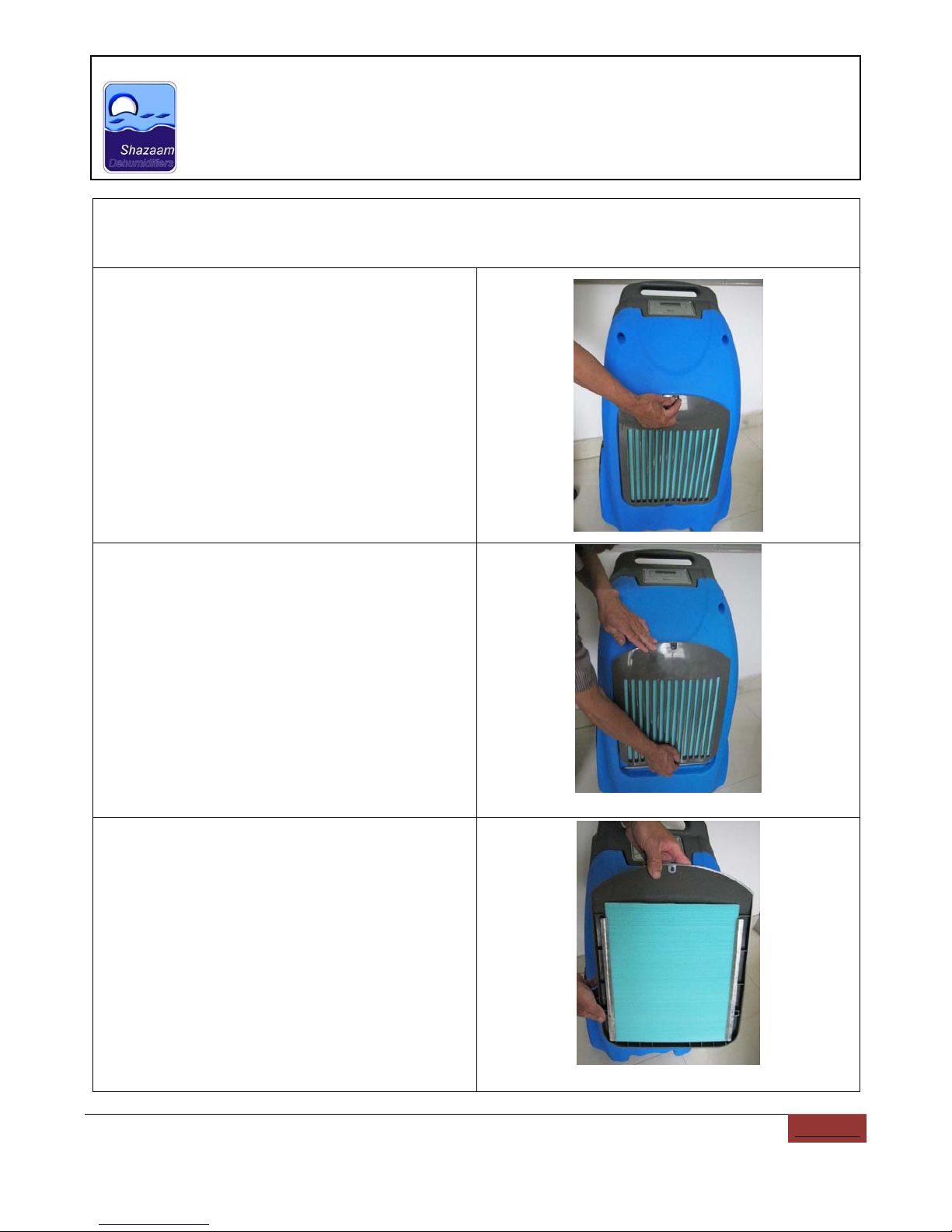
Q1: How to service the HAF filter?
A1:
Step 1:
Using hand to undo the screws
Step 2:
Slide the inlet cover from bottom to top.
Step 3:
Using the air gun to blow the dust off the HAF filter.
www.steambrite.com|4
Technical Service Manual
Model: DriStorm134, 134H, 184,184H
Revision 1: Dated 29 / 06 / 2011
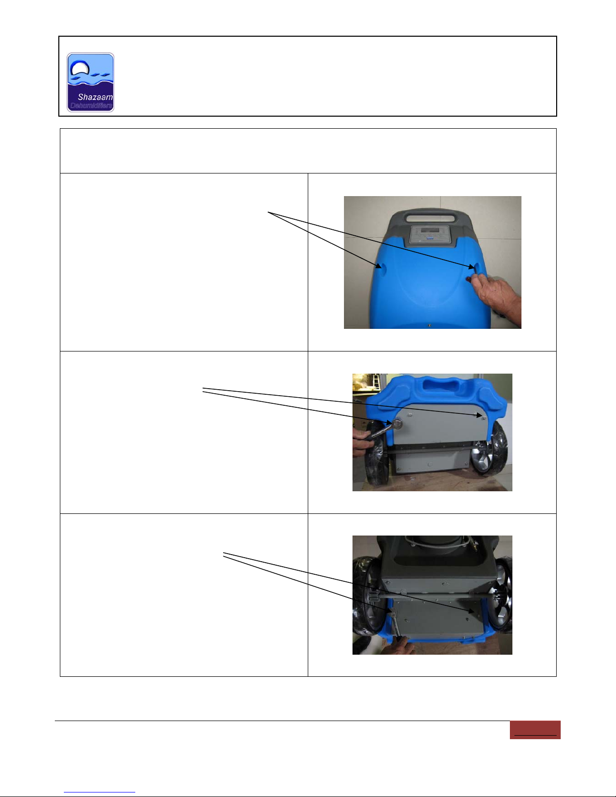
Q2: How to dismantle the front casing for servicing?
A2:
Step 1:
Using the “Allen Driver” to undo the two “HEX
SOCKET CAP SCREWS” on the top.
Step 2:
Using the “Hex screwdriver” to open the bottom
screws at the bottom.
Step 3:
Using the “Hex screwdriver” to open the back
bottom side of the front casing.

www.steambrite.com|5
Technical Service Manual
Model: DriStorm134, 134H, 184,184H
Revision 1: Dated 29 / 06 / 2011
Q3: How to detach the back casing from the main body for servicing?
A3:
Step 1:
Release the wire attached at the top of the casing.
Using the “Allen Driver” to undo the two “HEX
SOCKET CAP SCREWS” on the left.
Step 2:
Using the “Allen Driver” to undo the two “HEX
SOCKET CAP SCREWS” on the right.
Step 3:
Using the “Hex screwdriver” to open the four bottom
screws at the bottom.

www.steambrite.com|6
Technical Service Manual
Model: DriStorm134, 134H, 184,184H
Revision 1: Dated 29 / 06 / 2011
Q4: How to change the pump?
A4:
Step 1:
The pump is located at the bottom of the
dehumidifier.
zUndo four screws (two in the front and two at
the bottom.
zDisconnect the piping.
zPull the tube out of the pump.
Step 2:
Undo the screw and open top covering of the pump.
Step 3:
Unplug the connector and plug back a new pump.

www.steambrite.com|7
Technical Service Manual
Model: DriStorm134, 134H, 184,184H
Revision 1: Dated 29 / 06 / 2011
Q5: How to solve the dehumidifiers leaking problems?
A5:
Step 1:
Please check whether the piping, which connected
to the outlet of the pump, is kinked. You might need
to dismantle the back casing to check the piping all
the way to the back as well.
Step 2:
Check pump whether is working properly or not
zPress the “Purge” button on the control
panel and check there is any water has
been pump out.
zPut your hand onto the top of the top cover
and check whether there is any air
movement.
Step 3:
The floating switch in the pump is malfunction,
which led to the water in the reservoir can’t be
pumped out as it needs.
a) Open the pump top cover and check
whether the floating switch has been
tightened and installed in vertical position.
b) Open the reservoir covering to check
whether the floater is blocked by the dirt
and can’t move upward and backward
smoothly. If that is the case, cleaning the
shaft and the reservoir.
c) Check whether the floating switch is
function or not by using electronic
multimeter. See the figures and description
on the right.
From left to right, #1, #2 & #3 switches are
located in the shaft respectively as shown
in the above figure.
#1 switch is related to Yellow & White wires.
#2 switch is related to Black & White wires;
#3 switch is related to Blue & Red wire;
Note: white color wire is the common wire
of #1 & #2 switches
www.steambrite.com|8
Technical Service Manual
Model: DriStorm134, 134H, 184,184H
Revision 1: Dated 29 / 06 / 2011
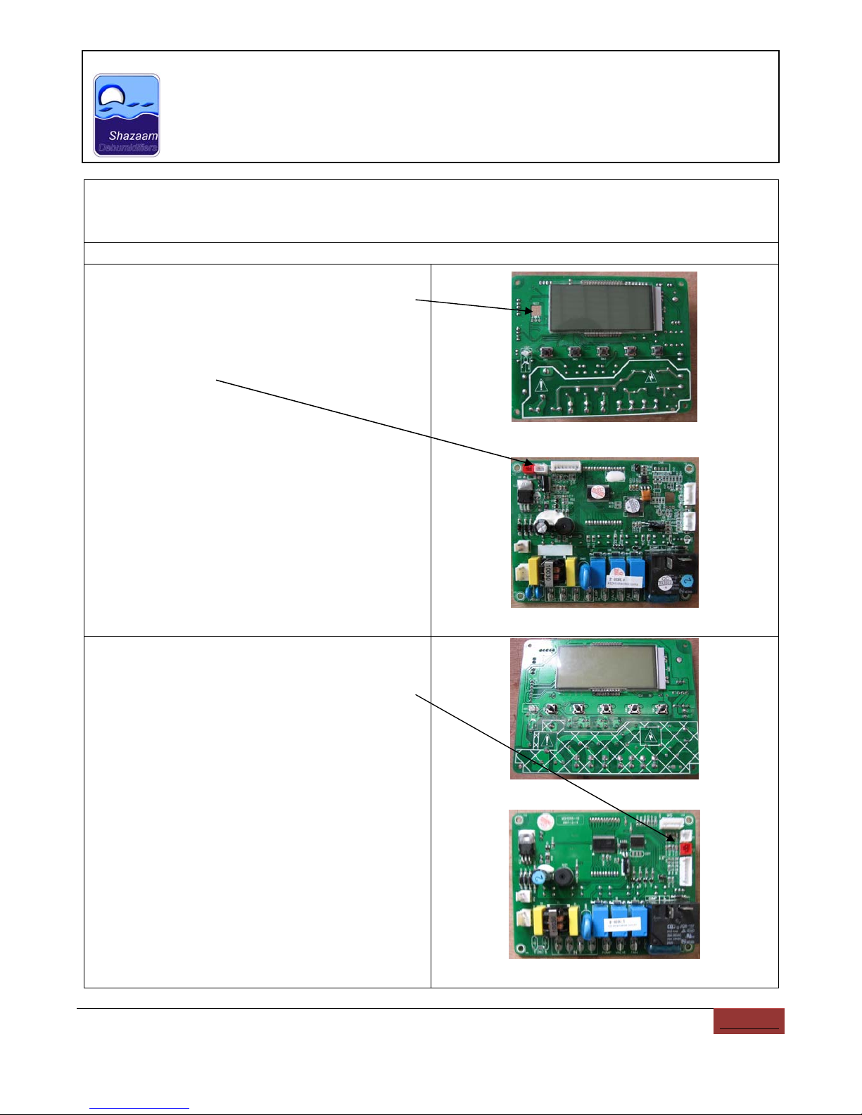
Q6: The difference between the DriStorm 1XX models and DriStorm 1XXH models?
A6:
1. Electronic Board
DriStorm 134H,184H
zThere is a hole on the electronic board.
zThere is an extra socket for humidistat
sensor.
zSome sockets are located in different way.
Front
Back
DriStorm 134,184
zThere is no hole on the electronic board.
zSome sockets are located in different way.
Front
Back

www.steambrite.com|9
Technical Service Manual
Model: DriStorm134, 134H, 184,184H
Revision 1: Dated 29 / 06 / 2011
Q6- Continue:The difference between the DriStorm 1XX models and DriStorm 1XXH
models?
A6- Continue:
2. Sensors
DriStorm 134H, 184H
zThe Humidistat sensor & ambient
temperature sensor are located in the front
of the coil.
DriStorm 134, 184H
zOnly the ambient temperature sensor is
located in the front of the coil. There is no
Humidistat sensor.
www.steambrite.com|10
Technical Service Manual
Model: DriStorm134, 134H, 184,184H
Revision 1: Dated 29 / 06 / 2011
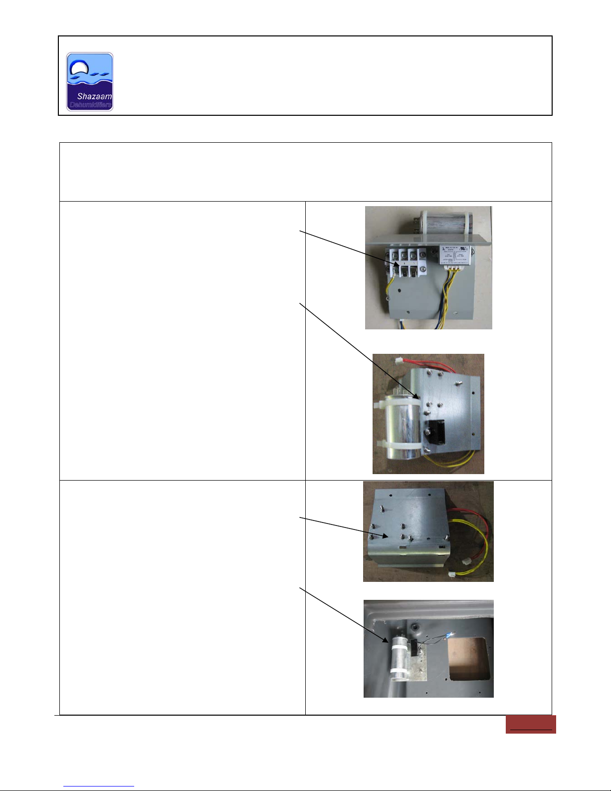
Q7: Where are the transformer, compressor capacitor, fan capacitor, terminal block are
located?
A7:
DriStorm 134, 134H
zThe transformer & terminal block are
installed onto the curve shape metal plate,
just underneath the control panel.
zThe compressor capacitor (round shape) &
fan capacitor (square shape) are also
located at the back of the curve shape
metal plate, just underneath the control
panel.
DriStorm 184, 184H
zThe compressor capacitor (round shape) &
fan capacitor (square shape) are NOT
located at the back of the curve shape
metal plate, just underneath the control
panel.
zThe compressor capacitor (round shape) &
fan capacitor (square shape) are also
located at the back of the square shape
metal plate, which is installed at the back
casing.
www.steambrite.com|11
Technical Service Manual
Model: DriStorm134, 134H, 184,184H
Revision 1: Dated 29 / 06 / 2011
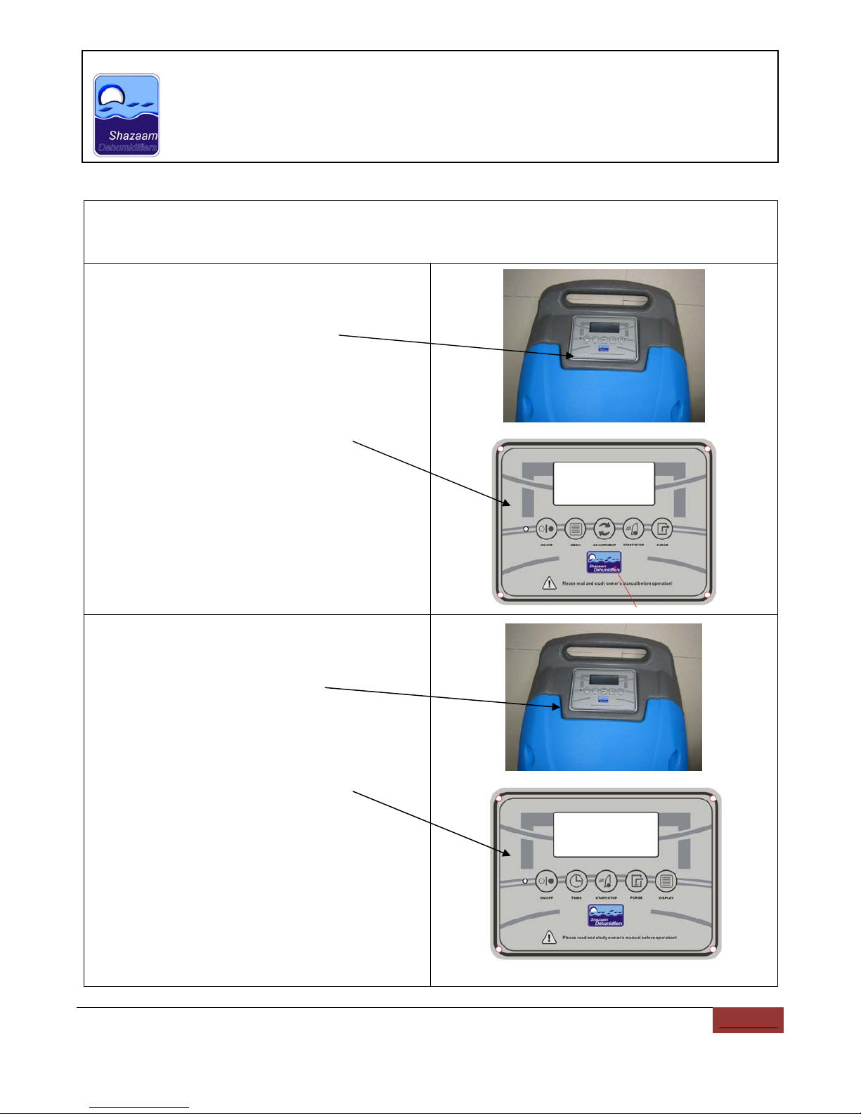
Q8: How to change the DriStorm 134, 184/ DriStorm 134H, 184H touch pad control panel?
A8:
DriStorm 134H, 184H
zUndo the four screws on the control panel.
Slightly move the control panel out of the
plastic casing.
zSee Annex 1 for DriStorm 134H, 184H
schematic diagram showing you how to
connect the wires.
zThe image on the right showing you what
does the control panel look like.
DriStorm 134, 184
zUndo the four screws on the control panel.
Slightly move the control panel out of the
plastic casing.
zSee Annex 2 for DriStorm 134,184
schematic diagram showing you how to
connect the wires.
zThe image on the right showing you what
does the control panel look like.
www.steambrite.com|12
Technical Service Manual
Model: DriStorm134, 134H, 184,184H
Revision 1: Dated 29 / 06 / 2011
Q9: The machine can’t turn on and there is no display on the LCD of the control panel.
A9:
Step 1: Check input power is 115V/60Hz or not.
Step 2: Check the BROWN color wire from the
terminal block (L terminal) to the Relay on
electronic board is well connected or not.
Step 3: Check the BLUE color wire from the
terminal block (N terminal) to N terminal on the
electronic board is well connected or not.
Step 4: Check the output of the transformer
voltage is in correct value (11V) or not.
Step 5: Check the fuse on the electronic board.
Step 6: If it is still not solve the problem, change
another electronic board.
Note: Please refer back to the schematic
diagram in Annex 1 & 2.

www.steambrite.com|13
Technical Service Manual
Model: DriStorm134, 134H, 184,184H
Revision 1: Dated 29 / 06 / 2011
Q10: The machine is not function, no water come out
A10:
Step 1:After turn on the machine, pressing on the
“Dehumidifier” button on the control panel and
check whether there is a “Water Drop” icon show up
on the LCD. If not, please change another control
panel.
Step 2: Investigate whether the compressor is
working or not by checking the evaporation coil is
getting cold or not.
If not, please check the followings,
a) Whether the wires from the compressor
end to the electronic end are connected
properly.
b) Check whether the compressor capacitor
is connected well and functioned well or
not.
c) Check Overload Protector of the
compressor is connected well and
functioned well or not.
Note: Please refer back to the schematic diagram in
Annex 1 & 2.
Step 3: Please check the fan is working or not.
a) Check the wires are connected well or not.
b) Check the fan capacitor is connected well
and functioned well or not.
Note: Please refer back to the schematic diagram in
Annex 1 & 2.

www.steambrite.com|14
Technical Service Manual
Model: DriStorm134, 134H, 184,184H
Revision 1: Dated 29 / 06 / 2011
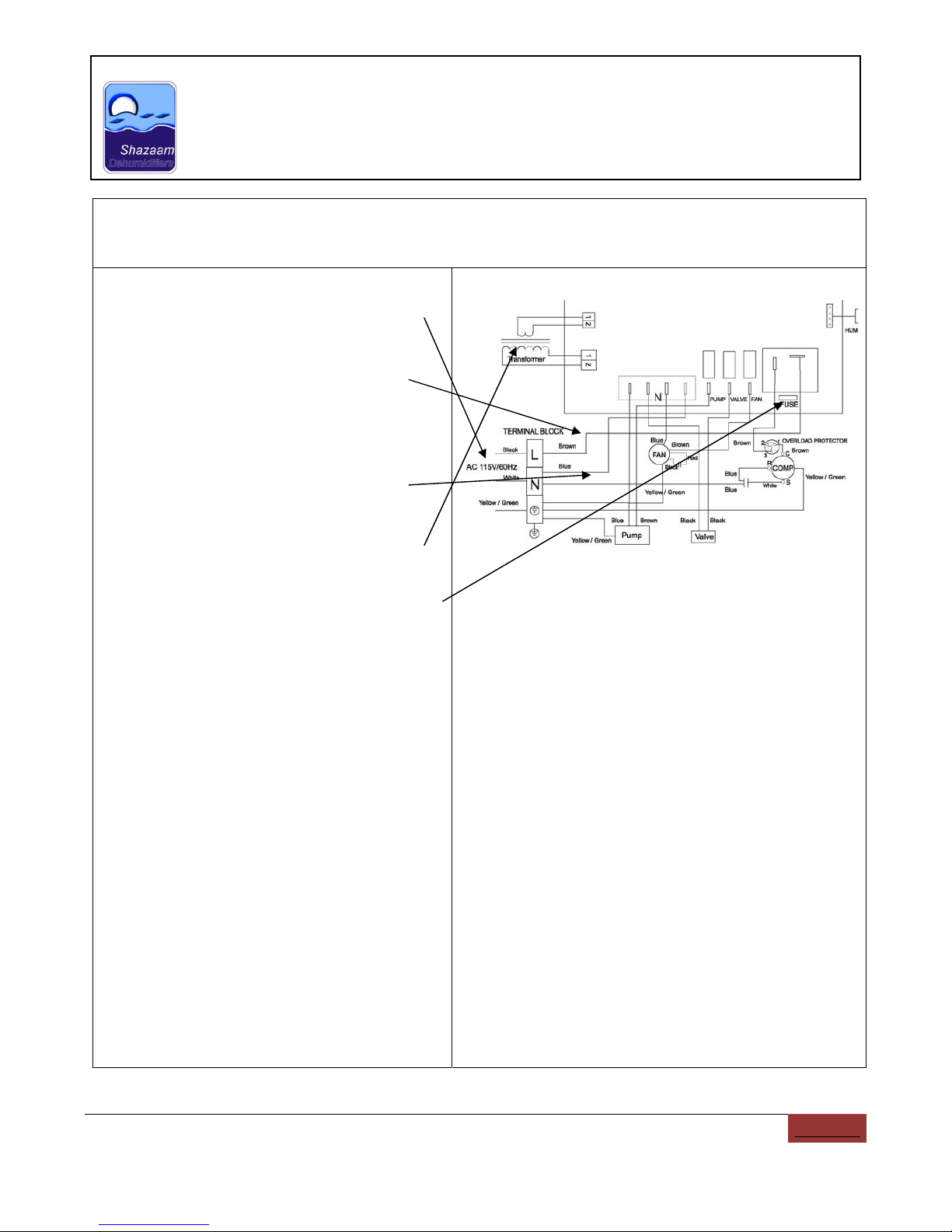
Annex 1:
SCHEMATIC DIAGRAM – Model: DriStorm 134H, 184H

www.steambrite.com|15
Technical Service Manual
Model: DriStorm134, 134H, 184,184H
Revision 1: Dated 29 / 06 / 2011
Annex 2:
SCHEMATIC DIAGRAM – Model: DriStorm 134, 184
This manual suits for next models
3
Table of contents
Other SHAZAAM Dehumidifier manuals

Popular Dehumidifier manuals by other brands

Dimplex
Dimplex DC12DE instruction manual

Santa Fe
Santa Fe COMPACT70 Installation & operation instructions

CTM International
CTM International DLW120 Operations & installation guide

COLUMBIA VAC
COLUMBIA VAC OPC1050N instruction manual

Haier
Haier AH102ACNAA Operation manual

Bionaire
Bionaire BD10 instruction manual


 BOUWDROGER manual")


