CTM International DLW120 How to use

OPERATION & INSTALLATION GUIDE
GUIDE D’UTILISATION ET D’INSTALLATION
AIR EXTRACTOR & DEHUMIDIFIER SYSTEM
SYSTÈME D’EXTRACTION D’AIR ET DÉHUMIDIFICATEUR
Model/Modele: DLW120
CUSTOMER SERVICE CENTER
SAVE THIS MANUAL and the original invoice for future
reference
Carefully check all packing materials before discarding
Do not assemble if there are missing pieces
Should you encounter problems after following all the
steps here in contained please contact our
Customer Support: Call 1-866-231-8893 or
email:info@ctm-inter.com
Kindly provide the model #, place and date of purchase
and a short description of the problems
CENTRE DE SERVICE A LA CLIENTELE
CONSERVEZ CE MANUAL avec la facture d’origine
pour reference future
Verifiez soigneusement tout l’emballage avant de jeter
les boites
Ne pas assembler s’il y a des pieces manquantes
Si vous rencontrez des problems apres avoir suivi
toutes les etapes ci-dessous,contactes notre
Service a la clientele : Composez le 1-866-231-8893 ou
Merci de fournir le numero du modele,le lieu et la date
d’achat et une breve description du probleme.

INSTALLATION GUIDE
SAFELY INSTRUCTIONS :
This fine product that you have just purchased is constructed from the highest quality
materials and workmanship.
Before installation and operation, we recommend the following procedures:
A
CHECK WITH YOUR LOCAL ELECTRICAL AUTHORITY TO ENSURE YOU COMPLY WITH LOCAL
ELECTRICAL REGULATIONS. THESE ELECTRICAL CODES HAVE BEEN DESIGNED FOR YOUR SAFTY.
BE SURE TO COMPLY WITH THESE CODES.
B
WE RECOMMEND THAT A SEPARATE AND DEDICATED CIRCUIT BE PROVIDED FROM YOUR HOME
ELETRICAL DISTRIBUTION PANEL. IT SHOULD BE PROPERLY PROTECTED WITH EITHER A FUSE OR A
CIRCUIT BREAKER. A GROUND FAULT CIRCUIT INTERRUPTER (GFCI) IS MADATORY. CONSULT A
LICENSED ELECTRICIAN FOR ALL WIRING.
C
THE GROUND TERMINAL ON THE THREE PRONG PLUG SHOULD NEVER BE REMOVED. THEY ARE
SUPPLIED AND DESIGNED FOR YOUR PROTECTION.
D
NEVRE MAKE ADJUSTMENTS TO ANY ELECRRICAL APPLIANCE OR PRODUCT WITH THE POWER
CONNECTED. BE SURE TO UNSCREW THE FUSE OR TRIP THE BBREAKER TO THE OFF POSITION AND
REMOVE THE POWER PLUG FROM THE RECEPTACLE BEFORE PROCEEDING
The necessary tools for the installation are:
-One (1) electric reciprocal saw or one de 6¼’’ (160 mm) hole saw
-One (1) electric drill with a 1¼’’ (32 mm) diameter drill bit
-One (1) Robertson or Philip screwdriver
-White (1) weather sea caulking for around the outside vent
Preparation

INSTALLATION GUIDE
INSTALL CRAWLSPACE UNITS so that there is a minimum of 24 inches (600mm) from the bottom of the
unit to the floor of the crawlspace to prevent dirt or debris from entering the suction fan
For all other units, do not install them where the suction fan is less than 39’’ (975mm) from the floor of
the room.
-The ideal location to install your unit is at the most humid part of your dwelling
-The Unit must be installed on the inside of an outside wall to allow an outside exit for the
exterior vent hole. The distance between the unit and the exterior vent hole should not be
more than 24 inches (600mm).
-The unit must be installed at a minimum of 10 feet (3 meters) from a high heat source such as
furnaces, boilers, radiators, baseboard heaters or any similar heat source
-
-Avoid placing the unit beneath a bedroom, as the noise of the fan motor may disturb some
people
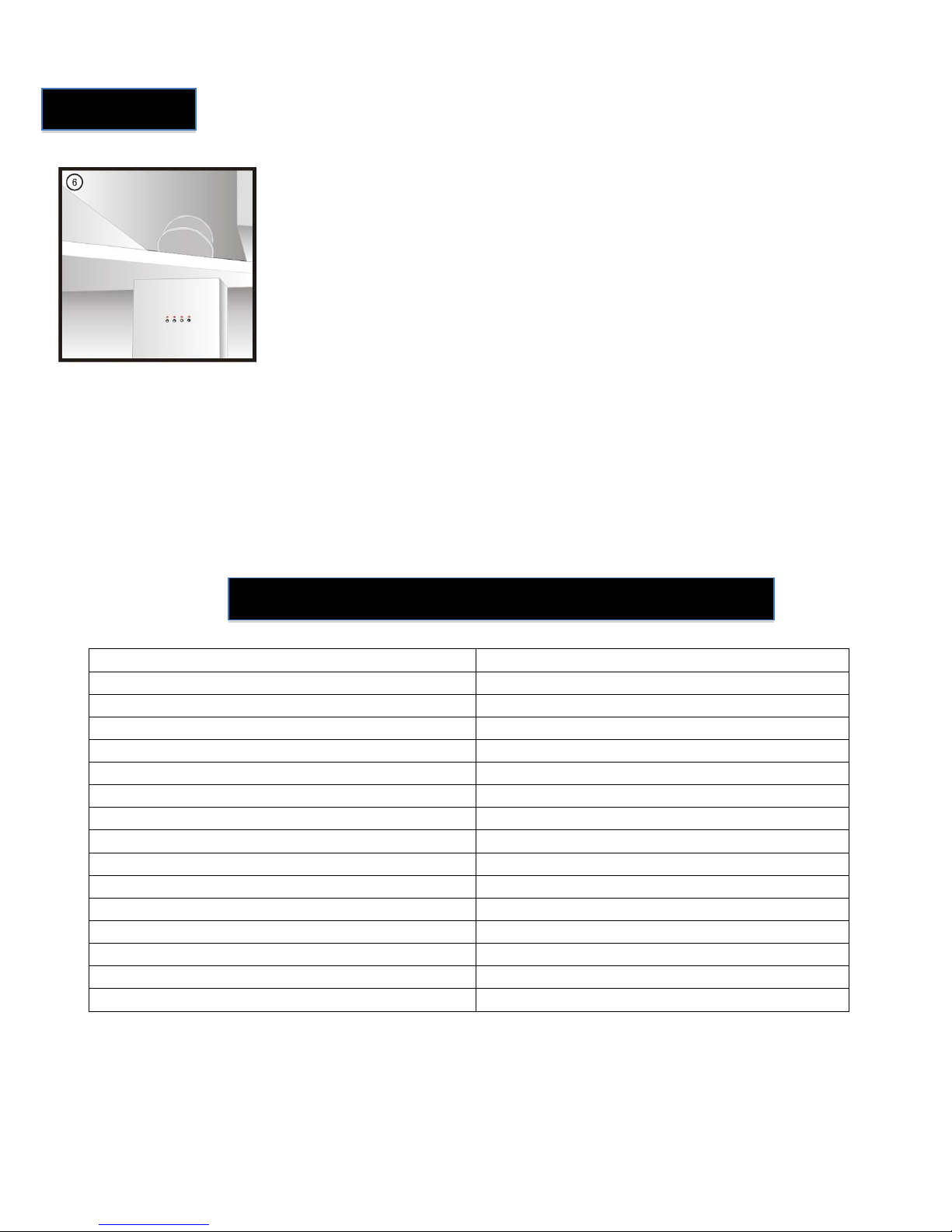
Select the appropriate location for the system.
It should be installed between the 2’’ x 10’’ ou
de 2’’ x 12’’ floor joists of the basement ceiling
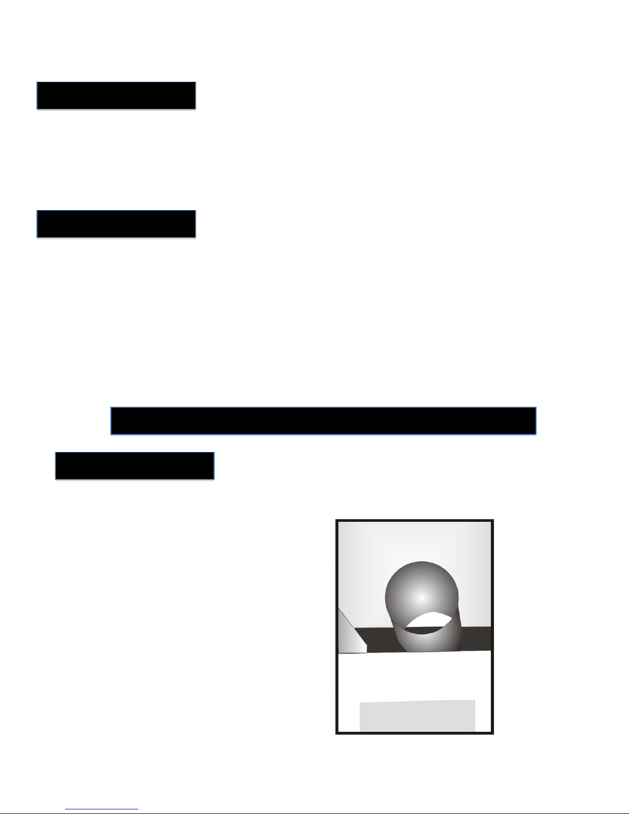
Determine the position of the air evacuation
pipe. Make sure the hole position will be above
ground level on the outside. Plan to leave a
space between the pipe and the floor joist to
avoid vibration. After choosing the idea
position, make on the wall what would be the
center opening of the pipe. Using your drill,
with a 1/4’’ (6mm) drill at the center opening
mark from the inside of the wall to the outside.
This drill hole will be used as a guide to drill the
final 6 ¼ ’’ (160mm) hole for the evacuation
pipe.
Warning
Location
INSTALLATION STEP BY STEP
STEP 1

From the center of the ¼’’ (6 mm), calculate a
distance of 7 5/8’’ (194 mm) below the hole and
make a horizontal line to mark the position of
the top of the upper wall support.
From the outside of the building, using the pre-drilled ¼’’ (6 mm) hole as a centre guide, drill a 6 ¼’’ (160
mm) hole from the outside to the inside of the house to allow the passage of the evacuation pipe.
STEP 2
STEP 3
STEP 4
Using the provided screws and anchors, fix
the long support to the wall. Then under the
long support fix the short wall support
leaving a 1/8’’ (3 mm) space between them.
STEP5
Still using the provided screws, fix the lower
suction tunnel to the wall support. To start,
screw the two mid screws first

Fix the base under the lower suction tunnel piece
directly to the wall.
Finally, install the bottom screws of the lower
suction tunnel pieces.
Place the upper suction tunnel piece above the
lower suction tunnel piece. The screws at the
bottom of the upper suction tunnel also secure
the top of the lower suction tunnel pieces.
Place the fan casing on the top of the upper
suction tunnel piece.
STEP 6
STEP 7
STEP 8

From the outside, slide in the evacuation pipe and adapt it to the elbow of the fan casing. This will show
you where to cut the length of this pipe to finalize the installation of the outside vent.
It may be necessary to make several longitudinal
cuts to the pipe end to secure the outside vent.
Apply the white weather seal caulking between
the outside vent and the outside wall to keep the
elements out.
If required, you can secure the fan casing using the provided set squares.
STEP 9
STEP 10
STEP 11
STEP 12

Connect the unit to a grounded receptacle (see safety instructions page 2).
At the time of connecting, the two center led lights will illuminate during the starting process. After 15-
20 second start-up cycle, you will be able to set the system according to your needs. At this time, the
winter LED light will remain on.
Based on the season, leave the setting under winter or push the summer button.
Low Summer Winter High
speed speed
The season setting are :
Summer: Relative humidity at 45% or less low speed
Relative humidity at 46% or more high speed
Winter: Relative humidity at 55% or less low speed
Relative humidity at 56% or more high speed
It is possible to override the seasonal settings. To keep the system at high speed, push the right side
button. To keep the system at low speed, push the left side button, To cancel the override process, push
the same button again.
Note : when you override the seasonal setting, the led light of the overridden season remains on.
Instead of fitting the fan casing between the floor joists, it is possible to modify the elbow to fix the fan
casing below the ceiling.
The following instruction describes how to modify the elbow inside the
Remove the top cover.
OPERATING THE UNIT
STEP 1
INSTALLATION ALTERNATIVE

Remover the plastic bulkhead from three-way pipe.
Place the plastic bulkhead to the position shown in the picture.
And change the direction of the top cover
Using the screws, re-install the top cover.
In this configuration, the distance between the celling and the suction support
11¼’’ (286 mm).
STEP 2
STEP 3
STEP 4
STEP 5

The last step is to fix the elbow (not included) pre-installed in the ceiling
PARTS
DESCRIPTION
CSJ23001
Suction tunnel (3 pieces)
CSJ23002
Suction tunnel supports (2 pieces)
CSJ23003
Fan Casing (2 pieces)
CSJ23004
Control Panel
CSJ23005
Circuit Board support (4)
CSJ23006
Circuit boards
CSJ23007
Relative humidity sensor kit
CSJ23008
Electric cord strain relief
CSJ23009
Electric cord
CSJ23010
Fan collar
CSJ23011
Fan and motor
CSJ23012
Evacuation three-way pipe
CSJ23013
Plastic bulkhead
CSJ23014
Evacuation pipe
CSJ23015
Louver vent hood
PART LIST
STEP 6

GUIDE D’INSTALLATION
CONSIGNES DE SÉCURITÉ :
Ce produit haut de gamme que vous venez d’acheter est fabriqué de matériaux de haute
qualité et d’une main d’œuvre attentionnée.
Avant l’installation et l’utilisation, nous recommandons les procédures suivantes:
A
VÉRIFIEZ AUPRÈS DE VOTRE AUTORITÉ EN MATIÈRE D’ÉLECTRICITÉ AFIN D’ASSURER VOTRE
CONFORMITÉ AUX RÈGLEMENTS LOCAUX SUR L’ÉLECTRICITÉ. CES CODES ÉLECTRIQUES ONT ÉTÉ
CONÇUS POUR ASSURER VOTRE SÉCURITÉ. EFFORCEZ-VOUS DE BIEN RESPECTER CES CODES.
B
NOUS RECOMMANDONS L’UTILISATION D’UN CIRCUIT SÉPARÉ ET DISTINCT À PARTIR DE VOTRE
PANNEAU DE DISTRIBUTION ÉLECTRIQUE. IL DOIT ÊTRE ADÉQUATEMENT PROTÉGÉPAR UN FUSIBLE
OU UN DISJONCTEUR DE CIRCUIT. UN DISJONCTEUR DE FUITE DE TERRE (DFT) EST OBLIGATOIRE.
VEUILLEZ CONSULTER UN ÉLECTRICIEN AGRÉÉPOUR LE CÂBLAGE.
C
LA PRISE DE TERRE SUR LA FICHE MOULÉE À TROIS BORNES NE DEVRAIT JAMAIS ÊTRE ENLEVÉE. ELLE
EST FOURNIE ET CONÇUE POUR ASSURER VOTRE PROTECTION
D
N’EFFECTUEZ JAMAIS D’AJUSTEMENTS À UN APPAREIL OU UN PRODUIT ÉLECTRIQUE QUELCONQUE
LORSQUE LE CORDON D’ALIMENTATION EST BRANCHÉ. ASSUREZ-VOUS DE DÉVISSER LE FUSIBLE OU
DÉCLENCHER LE DISJONCTEUR EN POSITION D’ARRÊT ET D’ENLEVER LA FICHE DE COURANT DE LA
PRISE AVANT DE PROCÉDER.
Les outils nécessaires à l’installation sont :
-Une (1) scie alternative ou une (1) scie cylindrique d’un diamètre de 6¼’’ (160 mm).
-Une (1) perceuse électrique avec une mèche d’un diamètre de 1¼’’ (32 mm).
-Un (1) tournevis carréou cruciforme.
-Calfeutrage étanche blanc pour le périmètre de l’évent extérieur.
Préparation

Pour prévenir l’infiltration de saleté ou de débris dans le ventilateur d’aspiration, INSTALLEZ DES
APPAREILS DE VIDE SANITAIRE afin qu’il y ait un minimum de 24 pouces (600 mm) entre le bas de
l’unité et le plancher du vide sanitaire.
Pour tous les autres appareils, ne les installez pas lorsque le ventilateur d’aspiration est à moins de 39’’
(975 mm) du plancher de la pièce.
-
-L’emplacement idéal pour installer votre unité est dans la partie la plus humide de votre
demeure.
-L’appareil doit être installé à l’intérieur, sur un mur extérieur afin de permettre l’échappement
par l’orifice de ventilation extérieure. La distance entre l’appareil et l’orifice de ventilation
extérieure ne devrait pas dépasser 24 pouces (600 mm).
-L’appareil doit être installé à au moins 10 pieds (3 mètres) d’une source de chaleur intense
telle qu’une fournaise, un chauffe-eau, un radiateur, des plinthes chauffantes, ou une source de
chaleur semblable.
-Éviter d’installer l’appareil au-dessous d’une chambre à coucher, puisque le bruit du moteur de
la ventilation risque de déranger les gens.
Sélectionnez un emplacement convenable pour
le système. Il devrait être installé entre la solive
de plancher de 2’’ x 10’’ ou de 2’’ x 12’’ au plafond
du sous-sol.
Déterminez la position du conduit d’évacuation
d’air. Assurez-vous que la position du trou sera
au-dessus du niveau du sol à l’extérieur.
Prévoyez laisser un espace entre le conduit et la
solive de plancher afin d’éviter les vibrations.
Après avoir choisi la position idéale, faites une
marque sur le mur pour indiquer le centre de
l’ouverture du conduit. En utilisant votre
perceuse équipée d’une mèche de 1¼’’ (32
mm), percez un trou sur la marque indiquant le
centre de l’ouverture, commençant au mur
intérieur vers l’extérieur. Ce trou sera utilisé
comme guide pour percer le trou final de 6¼’’
(160 mm) pour le conduit d’évacuation.
Avertissement
Emplacement
PROCÉDURE D’INSTALLATION ÉTAPE PAR ÉTAPE
ÉTAPE 1

À partir du centre du trou de ¼’’ (6 mm),
calculez une distance de 7 5/8’’ (194 mm) sous le
trou et faites une ligne horizontale pour marquer
la position du haut du support mural supérieur.
De l’extérieur du bâtiment et en utilisant le trou pré-percé de ¼’’ (6 mm) en tant que guide central,
percez un trou de 6 ¼’’ (160 mm) de l’extérieur vers l’intérieur du bâtiment pour permettre le passage du
conduit d’évacuation.
ÉTAPE 2
ÉTAPE 3
ÉTAPE 4
En utilisant les vis et les ancrages fournis,
fixez le long support au mur. Ensuite, fixez le
court support mural sous le long support,
laissant un espace de 1/8’’ (3 mm) entre les
deux.
ÉTAPE 5
En utilisant toujours les vis fournies, fixez le
tunnel d’aspiration inférieur au support mural.
Vissez premièrement les deux vis du milieu.

Fixez la base sous la pièce inférieure du tunnel
d’aspiration directement au mur.
Finalement, installez les vis du bas de la pièce
inférieure du tunnel d’aspiration.
Placez la pièce supérieure du tunnel d’aspiration
au-dessus de la pièce inférieure du tunnel
d’aspiration. Les vis au bas de la partie
supérieure du tunnel d’aspiration consolident
également le haut de la pièce inférieure du
tunnel d’aspiration.
Placez l’enceinte du ventilateur au-dessus de la
pièce supérieure du tunnel d’aspiration.
ÉTAPE 6
ÉTAPE 7
ÉTAPE 8

De l’extérieur, insérez le conduit d’évacuation et ajustez-le au coude de l’enceinte du ventilateur. Ceci
vous indiquera l’endroit où découper le conduit en termes de longueur, afin de pouvoir terminer
l’installation de l’évent extérieur.
Il pourrait être nécessaire de faire des incisions
longitudinales vers le bout du conduit afin de
fixer l’évent extérieur.
Appliquez le calfeutrage étanche blanc entre
l’évent extérieur et le mur extérieur afin de
protéger contre les éléments.
Si nécessaire, vous pouvez fixer l’enceinte du
ventilateur en utilisant les équerres fournies.
ÉTAPE 9
ÉTAPE 10
ÉTAPE 11
ÉTAPE 12

Branchez l’appareil à une prise à la terre (voir les consignes de sécurité à la page 2).
Suite à la connexion, les deux indicateurs centraux DEL s’illumineront lors du processus de démarrage.
Après un cycle de démarrage de 15 –20 secondes, vous pourrez configurer le système selon vos besoins.
À ce moment, l’indicateur DEL d’hiver demeurera allumé.
Selon la saison, choisissez le mode de réglage en appuyant sur le bouton «hiver »ou «été».
Faible vitesse Été Hiver Haute vitesse
Les réglages saisonniers sont les suivants :
Été: Humiditérelative à 45% ou moins faible vitesse
Humiditérelative à 46% ou plus haute vitesse
Hiver : Humiditérelative à 55% ou moins faible vitesse
Humiditérelative à 56% ou plus haute vitesse
Il est possible de neutraliser les réglages saisonniers. Afin de garder le système à une haute vitesse,
appuyez sur la touche de droite. Afin de garder le système àune faible vitesse, appuyez sur la touche de
gauche. Pour annuler ce processus de surpassement des réglages, appuyez de nouveau sur le même
bouton.
Note : Lorsque vous neutralisez les réglages saisonniers, le témoin DEL de la saison neutralisée demeure
allumé.
Au lieu d’ajuster l’enceinte du ventilateur entre les solives de plancher, il est possible de modifier le
coude afin de fixer l’enceinte du ventilateur au-dessous du plafond.
Les directives suivantes montrent comment modifier le coude à l’intérieur de l’enceinte.
Enlevez le couvercle supérieur.
UTILISATION DE L’APPAREIL
INSTALLATION ALTERNATIVE
ÉTAPE 1

Enlevez la cloison en plastique du tuyau àtrois voies.
Placez la cloison en plastique dans la position montrée sur l’image.
Modifiez l’orientation du couvercle supérieur.
En utilisant les vis, réinstallez le couvercle supérieur.
Dans cette configuration, la distance entre le plafond et le support d’aspiration est de
11¼’’ (286 mm).
ÉTAPE 2
ÉTAPE 3
ÉTAPE 4
ÉTAPE 5

La dernière étape est de fixer le coude (non fournis) préinstalléau plafond.
PIÈCES
DESCRIPTION
CSJ23001
Tunnel d’aspiration (3 pièces)
CSJ23002
Support du tunnel d’aspiration (2 pièces)
CSJ23003
Enceinte du ventilateur (2 pièces)
CSJ23004
Panneau de commande
CSJ23005
Support de carte de circuits (4)
CSJ23006
Carte de circuits
CSJ23007
Ensemble de capteur d’humidité relative
CSJ23008
Serre-câble du cordon électrique
CSJ23009
Cordon électrique
CSJ23010
Collet de ventilateur
CSJ23011
Ventilateur et moteur
CSJ23012
Tuyau d’évacuation à trois voies
CSJ23013
Cloison en plastique
CSJ23014
Tuyau d’évacuation
CSJ23015
Hotte de ventilation avec aérateur àlames
ÉTAPE 6
LISTE DES PIÈCES
Table of contents
Languages:
Popular Dehumidifier manuals by other brands

American Aldes
American Aldes DH-100V Installation, operation & service instructions

Argo
Argo NARCISO 12 instruction manual

Zibro
Zibro D4 operating manual

Tectro
Tectro TD 310 operating manual

Wood’s
Wood’s WCD6HGM user manual

Healthy Climate Solutions
Healthy Climate Solutions HCWHD4-080 installation instructions