Shell Solar SP150-L User manual

Shell Solar
Installation Guide
for Shell Solar Photovoltaic Modules
www.shell.com/solar/
First Edition 2003

Purpose of this guide
This guide contains information regarding
the installation and safe handling of
Shell Solar photovoltaic modules (hereafter
referred to as “modules“).
Please follow these instructions carefully
and observe all of the safety precautions.
Although this guide describes several typi-
cal systems using photovoltaic solar power
modules, it does not describe how to install
or operate such systems. Please consult your
solar power dealer for additional information
on the following subjects:
} dimensioning and constructing solar pho-
tovoltaic systems
} wiring materials
} connectors
} stands and supports
Before installing a solar photovoltaic system,
you should familiarize yourself with the
mechanical and electrical requirements for
such systems. For this reason, we recommend
that you read this guide completely before
starting the installation.
In the guide, the term ‘module’ should gener-
ally be understood to refer to individual
modules and/or groups of modules accord-
ing to the context.
Caution
If these products are used in the
USA, please observe the instruc-
tions marked ‘[USA]’.
General information
Installing solar photovoltaic systems may
require specialised skills and knowledge.
It should only be performed by qualified
electricians.
Caution
If the total DC voltage available
from several modules connected
in series (the sum of the open-cir-
cuit voltages of the individual modules) can
exceed 120 V, installation and commission-
ing of the system must be performed by a
licensed electrician or specialized company.
The installer assumes the risk of all injury that
might occur during installation, including,
without limitation, the risk of electric shock.
Shell Solar electric modules do not require
the use of special cable assemblies. All mod-
ules come with a permanently attached junc-
tion box that will accept a variety of wiring
applications or with a special cable assembly
for ease of installation. It is recommended
to utilize a qualified installer or reseller for
service.
WARNING
All instructions should be read
and understood before attempt-
ing to install, wire, operate, and
maintain the module. Contact with electrically
active parts of the module such as terminals
can result in burns, sparks, and lethal shock
whether the module is connected or discon-
nected.
Proper use
Photovoltaic solar modules produce direct-
current electrical energy from light. They are
designed for outdoor use, and depending on
their construction can be mounted on support
frames, stands, flat surfaces, vehicles or boats.
} Do not disassemble the module, and do
not remove any attached nameplates or
components.
} Do not apply paint or adhesive to the rear
surface.
} Do not use mirrors or lenses to artificially
concentrate sunlight on the module.
Table of Contents
Purpose of this guide 2
} General information 2
} Proper use 2
} Safety precautions for installing
a solar photovoltaic system 3
Product Identification 4
Mechanical Installation 4
} Selecting the location 4
} Selecting the proper support frame 4
} Ground/Roof/Pole mount 5
} Roof Mounting 5
} Mounting hole locations
} Installing frameless modules 5
} Unpacking and handling the module 6
Electrical Installation 7
} Off-grid electrical system with battery
storage using a charge regulator 7
} Off-grid electrical system with battery
storage using a self-regulating module 7
} Grid-connected electrical system 7
} Comparison of series and parallel wiring 8
} Use suitable solar-power wiring 8
} Use suitable connectors 8
} Installing solar-power wiring 8
} Electrical connections to the module 9
} Grounding 9
} Junction box arrangements 9
} Installing a ProCharger™ CR
cable junction box 10
} Connecting modules with
ProCharger™-S junction boxes 11
} Connecting modules with Spelsberg
junction boxes 11
} Connecting modules with permanently
attached cables but no plug connectors
(ProCharger™ junction box cover) 12
} Blocking diodes 12
} Bypass diodes 12
Commissioning and Maintenance 12
} Testing, commissioning and
troubleshooting 12
} Maintenance 12
} Testing and replacing bypass diodes 12
Disclaimer of Liability 13
SHELL SOLAR LIMITED WARRANTY
FOR PV-MODULES (“Limited Warranty”) –
(Excluding U.S.) 14
SHELL SOLAR LIMITED WARRANTY
FOR PV-MODULES (“Limited Warranty”) –
(U.S.) 15
2
3
When installing the system, observe all local,
regional and national statutory regulations,
such as obtaining a building permit. Also
observe local and national regulations with
regard to use on vehicles or boats.
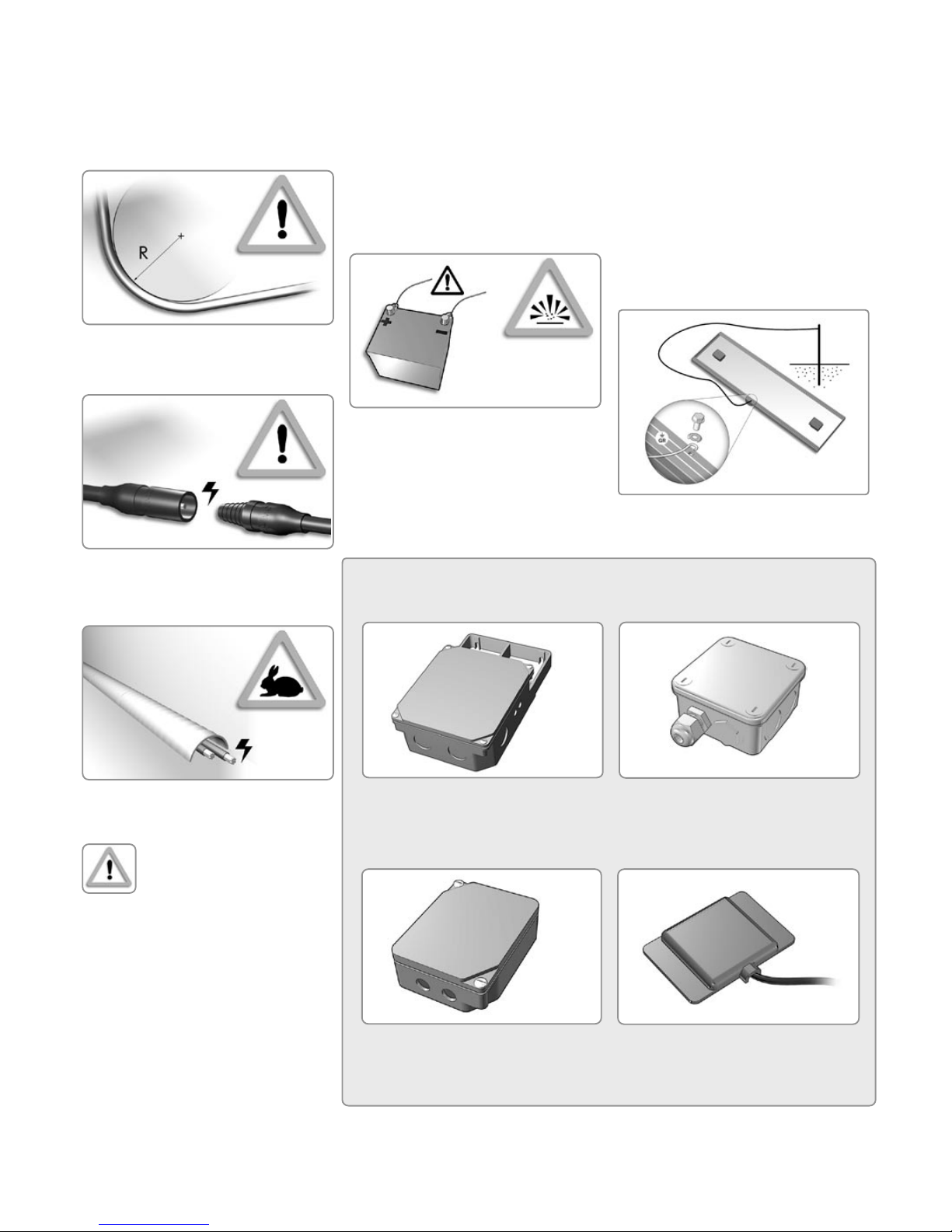
Safety precautions for installing
a solar photovoltaic system
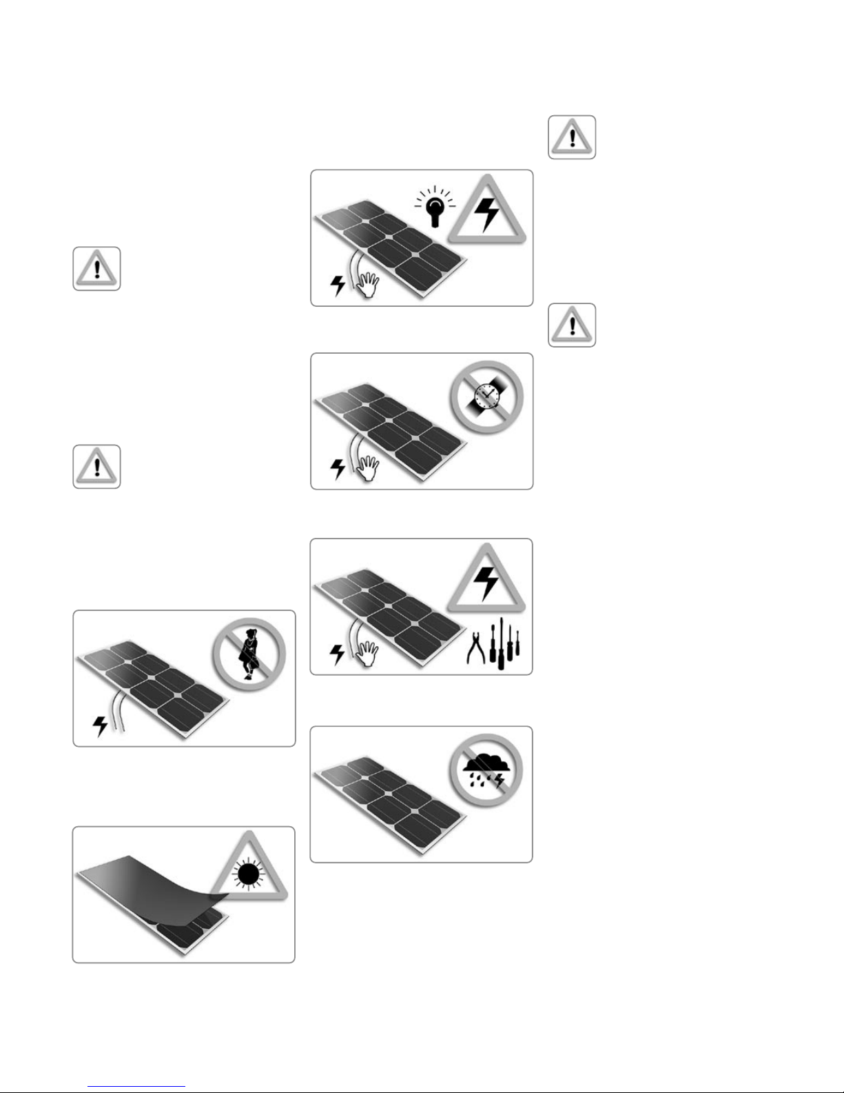
Caution
Solar modules produce electri-
cal energy when light shines on
their front surfaces, regardless of
whether they are connected. A system with
several modules can generate potentially
lethal voltages and currents.
If modules are connected in series, the total
voltage is equal to the sum of the individual
voltages. If they are connected in parallel,
the total current is equal to the sum of the
individual currents. Contact with a DC voltage
of 30 V or more is potentially hazardous.
Personal safety precautions:
} Respect the directives and regu-
lations of local authorities and/
or industrial accident prevention
organisations with regard to:
< working safely on roofs and
buildings
< electrical installations
} Keep children well away from the system
while installing mechanical and electrical
components.
} Completely cover the module with an
opaque material during mechanical and
electrical installation to stop electricity be-
ing generated.
} Do not touch electrical terminals or ends
of wires while the module is exposed to
light or while installing the module.
} Do not wear metallic jewellery while perfor-
ming mechanical or electrical installation.
} Use only insulated tools that are approved
for working on electrical installations.
} Work only under dry conditions, and use
only dry tools.
} Observe the safety regulations for all
other components used in the system,
including wiring and cables, connectors,
charging regulators, inverters, storage
batteries and rechargeable batteries, etc.
Operational safety and
reliability precautions:
} Use only equipment, connectors, wiring
and support frames suitable for use in a
solar electric system.
} Always use the same type of module
within a particular system.
} Keep this guide in a safe place for future
reference (care and maintenance) and in
case of sale or disposal of the module.
Instructions to ensure conformity
with the Underwriters Laboratory
Listings [USA]:
} For module wiring that is directly exposed
to weather, use only ‘UF’ type wiring with
solid or stranded copper conductors and
insulation resistant to sunlight (UV) and
weather.
} Observe the requirements listed in the
Technical Specifications for the type of
module used.
} The module frame must be earthed. If an
earth wire with a cross-section greater
than No. 10 AWG is used, a connector
that can be fastened to the module frame
using the supplied fastening screw must be
fitted to the module.
} Under normal conditions, a photovoltaic
module may experience conditions that
produce more current and/or voltage than
reported at standard test conditions. Ac-
cordingly, the values of short-circuit current
(Isc) and open-circuit voltage (Voc) marked
on UL listed modules should be multiplied
by a factor of 1.25 when determining
component voltage ratings, conductor
capacities, fuse sizes, and size of controls
connected to the module output. Refer
to Section 690-8 of the National Electric
Code for an additional multiplying factor
of 1.25 which may be applicable.
2
3

4
Ground mount Roof mount Pole mount
P
301134 A 2080200001
Serial No.
Serien Nr.
Class II Equipment
Power OutputRated Power Output
Schutzklasse II
Leistung
Nennleistung
Alle technischen Daten unter Standard-Testbedingungen
All technical data at standard test conditions: AM 1.5; G = 1000 W/m²; T cell = 25°C
Kurzschluss-Stro m Nennstrom
Short Circuit Current
Open Circuit Voltage
Leerlaufspannung
Rated Current
Rated Voltage
Nennspannung
MPP 150
Solar Modul Shell SP150-L
W
V
V 715
max
PMPP A
I 4,8
sc A
I 4,4
MPP
V
V 43,4
oc V
V 34,0
MPP
+
-5%
Shell Solar B.V.
P.O. Box 38000
1030 BN Amsterdam
The Netherlands Made in Germany
Berührung eine Gefahr dar! Berühren Sie keine Anschlußklemmen, wenn das Modul Sonnenlicht
Modulen erhöht die Spannung bzw. Stromstärke. Spannungen von dreißig Volt und darüber stellen bei
erzeugt bei Einstrahlung von Sonnenlicht elektrische Energie. Jede Reihen- oder Parallelschaltung von
anleitung aufgeführten Hinweise zu Sicherheitsvorkehrungen gelesen und befolgt werden. Dieses Modul
Vor Installation, Einsatz oder Wartung dieses Produktes müssen alle in der Montage- und Gebrauchs-
Warnung! Elektrische Gefahr!
Wenn zusammen mit den Modulen Batterien verwendet werden, ist den Sicherheitshinweisen des
ausgesetzt ist. Achten Sie darauf, dass in der Nähe von entzündbaren Gasen keine Funken entstehen.
Warning! Electrical Hazard!
des Produktes hat durch qualifiziertes Personal zu erfolgen.
Booten und Campingwagen ist der entsprechende Hersteller zu Rate zu ziehen. Installation und Wartung
Inspektion erteilen die örtlichen Behörden. Für die sachgemäße Installation auf Spezialfahrzeugen wie
elektrischen Bestimmungen installiert werden. Nähere Auskünfte über Genehmigung, Installation und
konzentrieren! Module und Traggestelle müssen gemäß den lokalen Vorschriften oder den nationalen
nicht abschatten! Sonnenstrahlen nicht mit Spiegeln, Linsen oder ähnlichen Hilfsmitteln auf das Modul
wassertauglich! Vermeiden Sie Beschädigungen des Modules durch spitze, scharfe Gegenstände. Zellen
Batterieherstellers Folge zu leisten. Module nicht in Flüssigkeiten eintauchen! Das Modul ist nicht see-
voltages/amperages are additive. Thirty volts or greater is considered a shock hazard.
electricity when exposed to sunlight. When modules are connected in series/parallel,
follow all safety precautions detailed in the instruction manual. This module produces
Before attempting to install, use and maintain this product, read, understand and
Do not contact terminals when module is exposed to sunlight. Do not produce sparks near flammable
vapors. Follow safety precautions of the battery manufacturer if batteries are used with modules. Do not
immerse in liquids. Module is not sea-water-resistant! Do not wear jewelry. Do not shadow cells. Do not
expose module to concentrated sunlight with mirrors, lenses or similar means. Install module and ground
frames in accordance with local codes or the National Electrical Code. Consult local authorities for
permit, installation and inspection requirements. Consult manufacturer for proper installation on special
vehicles such as boats and camper. Product should be installed and maintained by qualified personnel.
Keep module away from children.
Each module has a label on its rear side
providing the following information:
} The Module Type name - consisting of an
“S“ and a second letter which determines
the cell technology, followed by a number
that is equivalent to the rated power of the
module.
} The Serial Number - used to identify the
specific product. Each individual module
has a unique serial number.
} Rated Power, Rated Current and Rated
Voltage. All are characteristic values im-
portant for the design of your PV-system.
} The Open Circuit Voltage exceeds the
rated Voltage. Take care that the Open
Circuit Voltage multiplied by the number
of modules in series is not higher than the
Maximum System Voltage.
} Maximum System Voltage. This voltage is
certified per UL1703 and/or TÜV Safety
Class II.
} Warning Notes.
Do not remove the label. If the label is
removed the product warranty will no longer
be honoured by Shell Solar.
Product Identification Mechanical Installation
Selecting the location
Select a suitable location for installing the
module. It should be positioned such that it
is not shaded by other objects between 9 am
and 3 pm on the shortest day of the year. The
modules must be facing south in the northern
latitudes and north in the southern latitudes.
For detailed information on the best tilt angle
for your installation, please consult your local
solar power dealer.
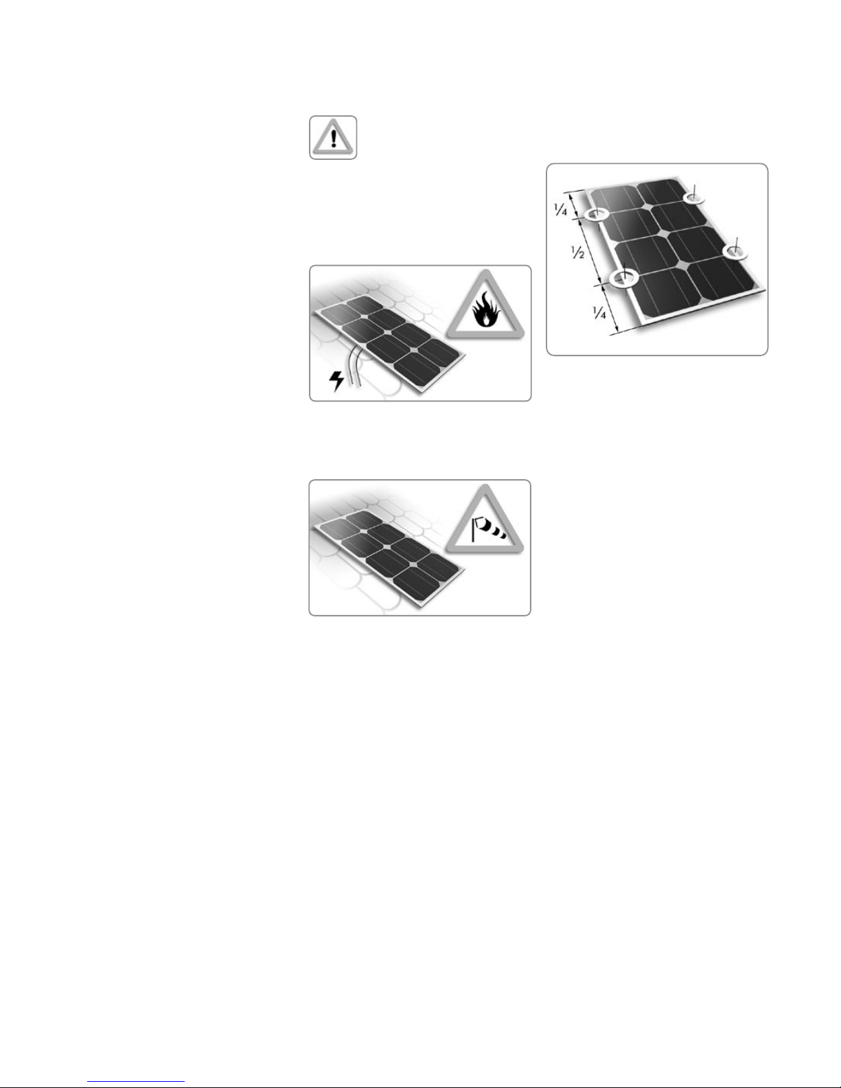
Caution
} The module should not be
shaded at any time of day.
} Do not use modules near equipment or
locations where flammable gases can be
generated or can collect.
Selecting the proper support frame
Always observe the instructions and
safety precautions included with the support
frame. If necessary, you can obtain more in-
formation from your dealer or sales partner.
Caution
} Do not drill holes in the frame
or glass of the module. Doing
so will void the warranty.
Modules must be securely attached to a
surface using support frames or installation
kits. The entire solar system must be able to
withstand the mechanical loads that are typi-
cal for the region where it is installed.
Make sure the support structure is strong
enough to withstand the anticipated wind
and snow loads according to local standards
and regulations.
Ensure that the modules are not subjected to
excessive forces due to thermal expansion of
the support structure.
The support structure should be made of
durable, corrosion-resistant and UV-resistant
material.
Support structures and installation kits for
many different uses are available from Shell
Solar and specialist companies. Ask your
dealer or sales partner for advice.
5
Mounting hole locations
quarter points
Ground mount:
Select the height of the mounting system to
prevent the edge of the lowest module being
covered by snow for a long period of time.
Also make sure the lowest module is placed
high enough so that it is not shaded by plants
or trees.
Roof mount:
When installing a module on a roof or
building, ensure that it is securely fastened
and cannot fall as a result of wind and snow
loads.
Observe prevailing safety regulations when
installing modules on roofs and buildings,
and use prescribed safety equipment (safety
nets, lifelines etc.).
Provide adequate ventilation on the rearside
of the modules. For proper operation and to
avoid damage from condensation, the mod-
ule requires an adequate flow of air across
the rear surface.
When installing the module, ensure that
there is sufficient distance between the rear
of the module and the mounting surface. The
minimum distance between the roof and the
modules should be 5 cm (2 Inches).
Pole mount:
When installing a module on top of a pole,
make sure the pole is strong enough to
withstand anticipated wind speeds and gusts
without substantial bending. The pole must
be installed with adequate foundations. Use
a mounting frame to fasten the module to the
top of the pole.
Roof Mounting
When installing modules on a roof, ensure
that the roof construction is suitable. In some
cases, a special support frame may be neces-
sary.
Caution
} The roof construction and
installation may affect fire
safety. Consequently, it may
be necessary to use components such as
earth ground fault circuit breakers, fuses
and circuit breakers. An improper instal-
lation can create an additional hazard.
Please consult knowledgeable experts
regarding the installation.
} When installing a module on a roof or
building, ensure that it is securely fastened
and cannot fall as the result of wind or
snow loads.
} Observe prevailing safety regulations
when installing modules on roofs and
buildings, and use prescribed safety
equipment (safety nets, lifelines etc.).
Mounting hole locations
For secure installation use only the recom-
mended mounting locations on the modules.
Wherever possible mount the module using
the predrilled holes in the frame. The most
secure mounting is achieved by mounting
the module using the four “quarter” points as
shown.
For modules with a slot in the frame on the
rearside, use the quarter points for the most
secure mounting.
Seek advise from your dealer if you intend
to mount the modules without using the pre-
defined mounting locations in the frame.
Shell Solar will not honour the product
warranty if additional holes are drilled in the
frame.
Installing frameless modules
Shell Solar supplies two types of frameless
modules - one type provided with factory as-
sembled (pre-mounted) clamps for mounting
and pre-certified to IEC61215, the other type
provided without factory assembled clamps
and certified as a UL recognised component
[USA].
Shell Solar will only warrant products if they
are installed in mounting systems which
are IEC or UL certified. IEC requires mount-
ing systems to be certified together with
the frameless modules being used. UL must
approve of the mounting method being used
with a frameless module before full UL ap-
proval can be obtained.
For any other mounting method contact your
Shell solar representative for more information.
General Requirements:
} Frameless modules are not suitable for
applications on vehicles, boats etc. for
mobile use.
} Frameless modules shall only be used in
regions with moderate snow loads and
wind speeds up to 130 km/h. - Frame-
less modules are vulnerable to breakage
during transportation and installation.
Handle them with care.
} No structures or objects that could touch
the module at its maximum permitted
flexure of 5 mm should be located in front
of or behind the module.
} The deviation of the four mounting
surfaces from a plane surface must not
exceed 1.2 degrees.
} The support surface at each mounting
position should have an area of at least
25 mm x 25 mm.
Frameless modules with pre-mounted clamps
A Shell Solar frameless module provided with
pre-mounted clamps is an IEC tested and
certified system and comes with the standard
Shell Solar product warranty.
} Attach clamps to a solid, clean and flat
surface
} Avoid putting the module under stress
when tightening the clamps. Do not create
any forces that could affect the module or
cause the clamps to pull away from the
module or slide towards the module.
} Use high quality M8 screws with strength
class 8.8 (in accordance with DIN
EN 24014) and washers compliant with
EN ISO 7093-8-200HV (minimum
diameter 24 mm, thickness 2 mm).
} We recommend using full-metal, self-lock-
ing nuts with spring-washers.
} Use a torque wrench and tighten the nuts
with a torque of 30 Nm.
} Two days after installing the modules test
all screws for proper tightness using a
torque wrench.
} Always arrange frameless modules in
landscape position with the mounting
clamps along the bottom and top edges. If
positioned in portrait position, the narrow
bottom edge must be secured against
slipping.
[USA] Frameless modules without
pre-mounted clamps
This product is a UL recognized component
and can only be used with a UL certified
mounting system. Follow strictly the instructions
in the installation guide of the mounting system.
Provide adequate rear ventilation
For proper operation and to avoid damage
from condensation, the module requires an
adequate flow of air across the rear surface.
When installing the module, ensure that
there is sufficient distance between the rear
of the module and the mounting surface. For
roof-mounted modules, the minimum distance
between the roof and the modules should be
5 cm (2 in).
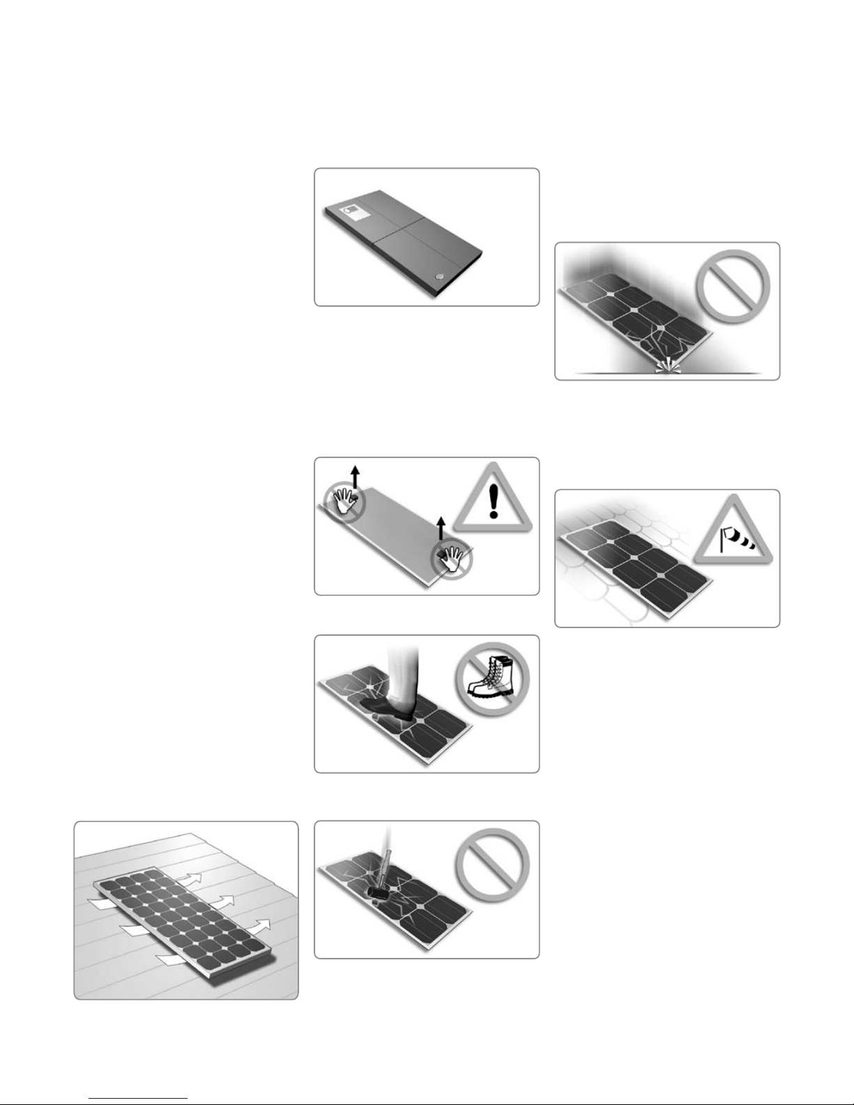
Unpacking and handling the module
} Leave the module in its package until you
are ready to install it.
} When installing or working with module
or wiring, cover module face completely
with opaque material (e.g. cardboard
packaging) to halt prodution of electricity.
These precautions are not necessary if the
module is fitted with a connecting cable
and a shock proof plug connector.
} Do not use the attached junction box to
hold or transport the module.
} Do not stand or step on module.
} Do not drop module or allow objects to
fall on module.
} To avoid glass breakage and damage to
the module, do not place any heavy ob-
jects on the module or on its rear surface.
Avoid setting the module down hard on
any surface, particularly when placing it
on a corner. Do not lay the module on an
uneven surface. If the glass of the module
is broken, it cannot be used.
} Do not carry out installation work for
modules on roofs or buildings when there
are strong winds. There is also a risk of
damage or injury from wind forces when
lifting or moving support frames with
several attached modules.
6
7

Off-grid electrical system with battery storage
using a charge regulator
Typical off-grid electrical system with battery
storage using a self-regulating module
Typical Photovoltaic system coupled to the public electricity grid
1 solar modules
2 inverter
3 utility meter (electricity generated)
4 utility grid
5 utility meter (electricity drawn)
6 appliances
1
2
34
5
6
6
There are many different applications for
photovoltaic solar energy systems. This guide
describes some of the most important typical
uses as representative examples.
Off-grid electrical system with battery stor-
age using a charge regulator
Solar power systems are frequently used to
supply electrical power to technical equip-
ment, remote cottages and hunting cabins,
camping vehicles and boats. In such systems,
the photovoltaic system charges a storage
battery via a charging regulator. The charg-
ing regulator controls the charging proc-
ess in order to protect the battery against
overcharging and ensure long battery life. If
necessary, an inverter can be used to provide
electrical power from the storage battery to
equipment operating at the normal mains
voltage.
Off-grid electrical system with battery stor-
age using a self-regulating module
When a self-regulating module is used, it is
not necessary to use a charging regulator.
The charging current provided by the self-
regulating module depends on the charge
state of the battery and decreases as the
battery voltage increases. This means that
during daylight hours, the charging current
automatically adjusts to suit the charge state
of the battery and the power consumption of
the connected loads.
} When using a self-regulating
module, make sure there is
sufficient battery capacity.
In the dark a small current could flow from
the battery and through the module. This
can reduce the state of charge of the battery
during the night. To eliminate this reverse
current, connect a “blocking diode” in series
between the solar module and the battery.
Use a diode that is specified for a current
that is at least 1.5 times more than the
maximum current generated by the module.
Mount the diode in such a way that allows
for proper cooling of this device. Please
check with your dealer for an appropriate
diode type.
Grid-connected electrical system
For this purpose, the electrical energy
generated by the solar power system
is supplied to the public electricity grid.
The structure and dimensioning of the system
vary from system to system. Usually, several
modules are connected in series to form a
block, and several blocks are connected in
parallel to a network inverter that links the
photovoltaic solar power system to the public
electricity grid. The amount of power fed into
the public electricity grid can be measured
using a supplementary meter. See “Compari-
son of series and parallel wiring“, page 8.
The amount of compensation paid for the
power fed into the public electricity grid de-
pends on contractual agreements with elec-
tricity companies and statutory provisions.
A permit is always required for any system
coupled to the public electricity grid, and
such a system must be formally approved
and accepted by an authorised expert.
Electrical Installation
6
7
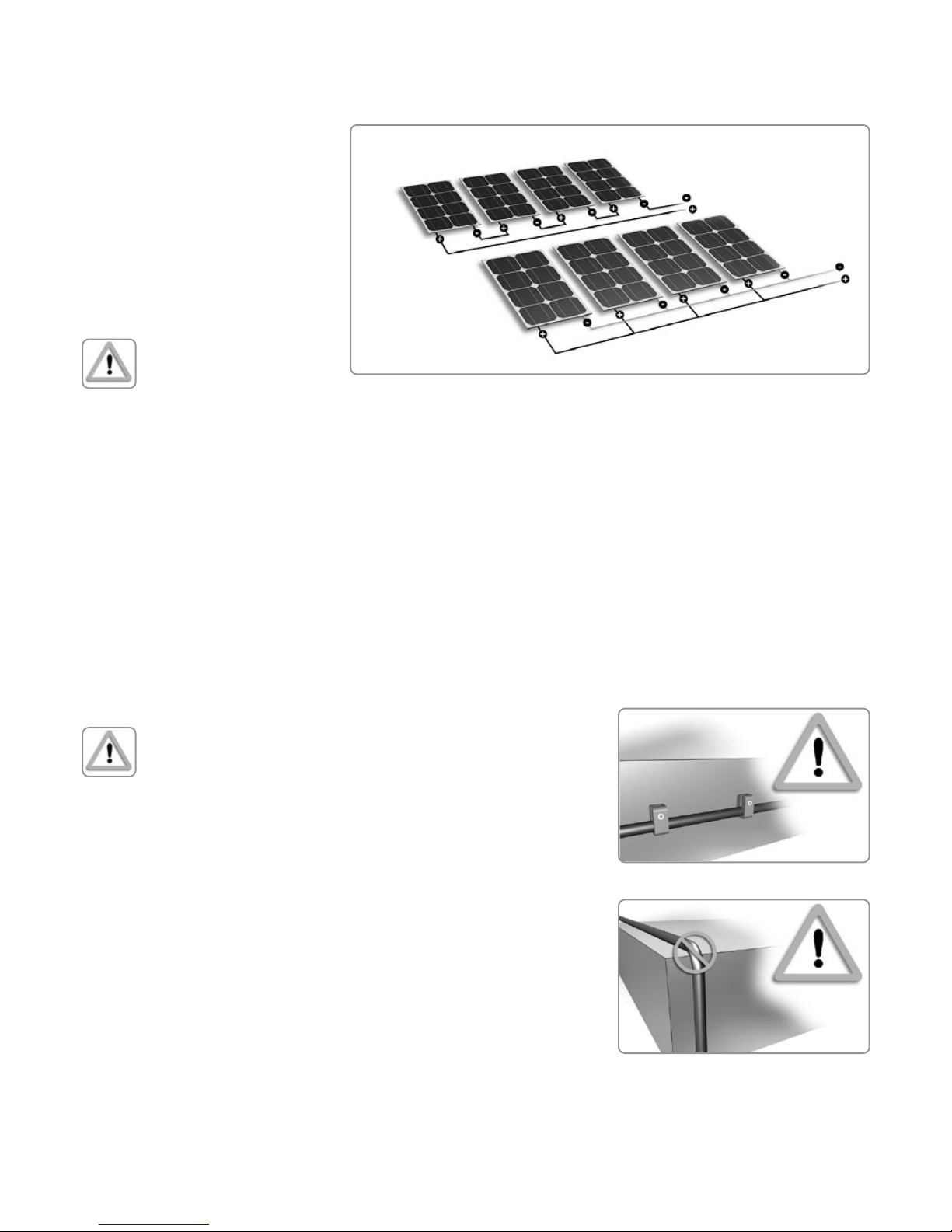
series wiring
parallel wiring
If you select or assemble your own wiring for
a photovoltaic solar power system, please
observe the following points:
} Use only wiring material that is specifi-
cally intended to be used in photovoltaic
solar power systems.
} At extreme low temperatures the cable
should be handled with more than usual
care.
} Select wiring material with insulation that
is UV-resistant and weatherproof. It should
have a rated voltage of at least 600 V.
} The cross-sectional area of the (stranded)
conductor depends on the maximum
short-circuit current and the overall length
of the wiring.
} If you use multi-conductor cable, the
insulation of the individual conductors
must be resistant to damage resulting from
movement
Typically, conductors with a cross-sectional
area of at least 2.5 mm2 are used, although
4 mm2 is recommended. Shell Solar recom-
mends using wiring specially designed for
solar power systems. Ask your dealer to
recommend manufacturers that can provide
cables with connectors made to meet your
requirements.
Use suitable connectors
If you select or assemble connectors for a pho-
tovoltaic solar power system, please observe
the following points:
} Use only connectors that are specifically
intended to be used in photovoltaic solar
power systems.
} Use the tools recommended or prescribed
by the connector manufacturer for assem-
bling connectors.
} Do not unplug a connector while the circuit
is under load. It is OK to unplug a connec-
tor while the circuit is ‘live’.
} Use protective caps to guard loose con-
nectors against the effects of weather.
Special connectors for solar power system
are commercially available - ask your dealer.
Installing solar-power wiring
Correctly installed wiring assures reliable
long-term operation of the photovoltaic solar
power system. Please observe the following:
} Keep cable length as short as possible to
reduce efficiency / voltage drop.
} If you connect several modules together,
secure the wiring to the support frame.
} Where possible, use suitable fasteners to
restrict the range of motion of loose sec-
tions of wiring.
} Avoid running wiring over sharp edges.
Comparison of series and parallel wiring
For applications with a high operating volt-
age, several photovoltaic modules can be
connected in series:
Vtotal = V1+V2+Vn
Itotal = I1 = I2 = In
A photovoltaic system with a high open-cir-
cuit voltage is suitable for use with a battery
storage system having an operating voltage
of 48 V or more.
} The maximum open-circuit
voltage of the system must not
be greater than the specified
maximum system voltage for
the module.
} There is an increased risk of short circuits
and arcing with high DC voltages. Use
adequately insulated wiring and connectors
that are approved for use at the maximum
open-circuit voltage.
For applications with a high current con-
sumption, several photovoltaic modules can
be connected in parallel:
Itotal = I1+I2+In
Vtotal = V1 = V2 = Vn
A parallel wiring is suitable for use in sys-
tems containing low-voltage loads with high
power consumption, or for optimising the
charging process with high-capacity battery
storage systems.
} The wiring and connec-
tors can become overheated
at high currents. Use wiring
with suitable cross-sectional
areas and connectors that are approved
for use at the maximum short-circuit cur-
rent. Observe the manufacturer’s instruc-
tions and local electrical code.
} It is recommended to use additional
junction boxes when connecting several
modules in parallel. Modules with conduit
ready (CR) ProCharger™ junction boxes
can be directly connected in parallel.
Use suitable solar-power wiring
Modules supplied with pre-assembled cables
can easily be connected to other modules
or matching electrical components, such as
charge regulators or inverters, using plug
connectors.
8
9
Correct connection of the grounding wire [USA]
} Observe the allowable minimum bending
radius for the type of wire used.
} Never open electrical connections or un-
plug connectors while the circuit is under
load.
} Cable conduits should be used in locations
where the wiring is accessible to children
or small animals.
Electrical connections to the module
} Fully cover the module with an
opaque material during
mechanical and electrical
installation.
} Protect the wiring against damage.
} Grounding must be performed in compli-
ance with all national standards and regu-
lations (see “Selecting the proper support
frame“, page 4).
} Connecting a module to a battery with
the leads reversed (reversed polarity) can
cause:
< damage to the bypass diode in the
module,
< a risk of explosion due to excessive gas
generation in the battery.
Grounding
Ground the modules and the support frame.
Modules with frames have a predrilled hole
in the lateral frame member for fitting a
No. 10 self-threading clamping screw and
washer. [USA]
Junction box arrangements
ProCharger™ CR junction box,
see page 10.
Note, some CR boxes do not have the
“handle“ configuration as shown here.
ProCharger™ S junction box,
see page 11.
} If the ground wire is not fitted with a ring
lug, first insert the clamping screw with the
dished washer into the drilled hole.
} Strip 16 mm of insulation from the end
of the conductor, and pass the bare wire
between the head of the screw and the
washer.
} Finally, tighten the screw.
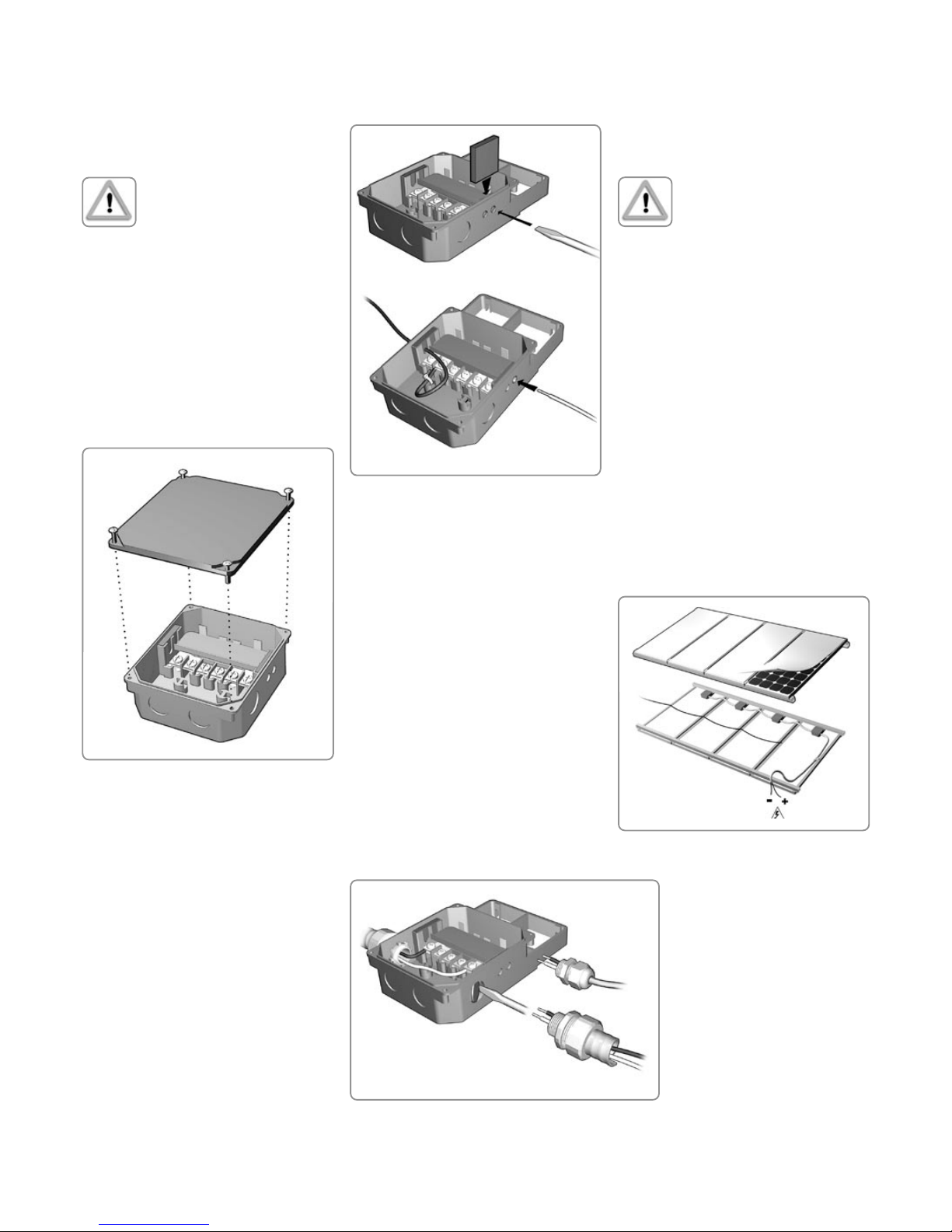
Spelsberg S junction box,
see page 11.
Note, some S junction boxes have 2 cable
glands.
ProCharger™ terminal cover,
see page 12.
8
9
Wiring ProCharger™ CR cable junction box
Waterproof ” cable fitting or conduit fitting
Cover the module with an opaque
material during installation
Installing a ProCharger™ CR
junction box
Match the polarities of the
cables and terminals when
making the connections.
Opening the junction box
} The ProCharger™ - CR junction box has
four captive screws that secure the lid to
the base. To remove the lid, loosen the
screws with a small flat or Phillips screw-
driver.
} Once wiring is complete, install the
junction box lid and tighten screws to
0.5 - 0.7 Nm (4 - 6 in-lb.).
Caution, DO NOT OVERTIGHTEN
the lid screws.
} Do not use sealant to bond lid to its base.
Wiring
} Remove the knockout plug from the entry
by carefully punching it out with a screw-
driver.
} Slide the foam seal into the cavity behind
the cable entry and press it down using a
screwdriver.
} Strip 16 mm of insulation from the end
of the wire. Wire size must range from 8
AWG - 14 AWG (1.5-10 mm²)
} Pass only one wire through the wire entry
by pressing it through the foam seal.
} Route the wire around the strain relief,
and then pass the bare end between the
clamping plate and the washer of the
screw. Tighten the screw to a maximum
torque of 2.3 Nm.
Waterproof ” cable fitting or
conduit fitting
You will need a UL-approved ” cable fit-
ting. Refer to the manufacturer’s instructions.
} Remove the knockout plug by placing the
tip of a screwdriver at the edge of the
plug and striking the screwdriver with a
hammer.
} Attach the fitting to the junction box and
leave it loose.
} Pass the wire through the fitting and route
it to a terminal. Be careful to select the
proper polarity.
} Insert the wires between the clamp-
ing plates and the washer of the screw.
Tighten the screw to a maximum torque of
2.3 Nm.
} Tighten the fitting.
The same procedure should be used
for a conduit fitting.
Interconnecting several modules with
ProCharger™ cable junction boxes
Use conduit fittings in all places
where the wiring is accessible to
children or small animals.
Series circuit:
} Connect the negative terminal of each
module to the positive terminal of its adja-
cent module.
} Fasten loose lengths of wiring using UV-
and weather-resistant cable clamps.
} At the first and last modules in the series,
replace the regular cable fitting for the
wire leading away from the module with
a conduit fitting. To remove the fitting,
loosen its lock nut.
} If a regular cable fitting is present at the
first and last modules of the series, replace
it with a conduit fitting.
Parallel circuit see “Comparison of series and
parallel wiring“, page 8.
Use a conduit fitting that can be used to route
the cable leading from each module group
connected in parallel.
After making the electrical
connections …
} Replace the covers on the
junction boxes and carefully
tighten the four retaining screws
(0.5-0.7 Nm). Do not apply any
supplementary sealant to the
junction boxes.
10
11

Wiring ProCharger™-S-junction box
ProCharger™-S-junction box
with two terminals
ProCharger™-S-junction box
with a single terminal
Spelsberg-junction box with two terminals
Spelsberg-junction box with a single terminal
Connecting modules with
ProCharger™-S junction boxes
Always check the polarity of
the cables and the junction box
terminals.
Opening the junction box
} To open the junction box, use a Philips
screwdriver to loosen the retaining screws.
Versions
Junction box with a single terminal
(single pole).
Do not remove the plastic cover
from the unused terminal.
Wiring
} Strip 16 mm of insulation from the end of
the wire. Wire size must range from
12 AWG - 16 AWG (1.5-4 mm²)
} Pass only one wire through the wire entry
by pressing it through the foam seal.
} Pass the bare end between the clamping
plate and the washer of the screw. Tighten
the screw with a maximum torque of
2.3 Nm
} If strain relief is necessary, route the wire
along the bracket, pass a short cable tie
through the slot and secure the cable tie.
After making the electrical
connections……
} Replace the covers on the junction boxes
and carefully tighten the four retaining
screws (0.5-0.7 Nm). Do not apply any
supplementary sealant to the junction
boxes.
Junction box with two terminals (dual pole).
Connecting modules with Spelsberg
junction boxes
Opening the junction box
} To open the junction box, use a flat-blade
screwdriver to loosen the retaining screws.
Versions
Junction box with a single terminal (single
pole).
Junction box with two terminals
(both poles).
Wiring
} Strip 16 mm of insulation from the end of
the wire.
} Loosen the nut of the cable fitting.
} Pass the wire through the fitting and
route it to the terminal. Pay attention
to the polarity.
} Using a small flat-blade screwdriver, press
down on the terminal clamp. Feed the
end of the wire into the opening in the
terminal.
} Tighten the nut of the cable fitting.
After making the electrical connections…
} Replace the covers on the junction boxes
and carefully tighten the four retaining
screws (0.5-0.7 Nm). Do not apply any sup-
plementary sealant to the junction boxes.
10
11
12
Replacing a bypass-diode in
a ProCharger™-CR-junction box
Connecting modules with permanently at-
tached cables but no plug connectors
(ProCharger™ junction box cover)
Crimp-type connectors are recommended.
If spliced joins are used, they should be
soldered, and they must be protected against
corrosion and short circuits with insulating
tape.
For more detailed information, refer to:
} ‘Installing solar power wiring’ (page 8)
Modules with permanently
attached cables may only be con-
nected in parallel. Never connect
such modules in series.
Blocking diodes
Blocking diodes prevent current from flowing
from the battery to the module when no elec-
tricity is being generated. It is recommended
to use blocking diodes when a charging
regulator is not used. Your specialist dealer
can advise you with regard to suitable types,
such as Schottky diodes.
If it is necessary to connect modules in
parallel within a series circuit, the integrated
diodes will not be able to equally distribute
the current. In this case, a supplementary
blocking diode must be used as follows:
} Connect the modules in parallel, and
connect a large external diode across the
parallel group
} Fit a heat sink to the diode.
Bypass Diodes
In systems with more than two modules in se-
ries high currents can flow through cells in the
reverse direction in the case of partial shading
(where part of a module is shaded and the
rest is exposed to the sun). These currents can
cause the affected cells to get very hot and
could even damage the module. To protect
modules from such high reverse currents, by-
pass diodes are used. All Shell modules rated
greater than 40 Watt have bypass diodes
already integrated in the junction box.
In the unlikely event of diode failure, a re-
placement can easily be fitted.
Commissioning and Maintenance
In the case of modules with CR cable junction
boxes, do not disconnect the wires from the
terminals. If the voltage across the terminals
differs from the rated value by more than 5
percent, this indicates a bad electrical con-
nection.
Maintenance
Shell Solar recommends the following main-
tenance in order to ensure optimum perform-
ance of the module:
} Clean the glass surfaces of the module
as necessary. Always use water and a
soft sponge or cloth for cleaning. A mild,
non-abrasive cleaning agent can be used
to remove stubborn dirt.
} Check the electrical and mechanical con-
nections every six months to verify that
they are clean, secure and undamaged.
} If any problems arise, have them be inves-
tigated by an authorised specialist.
Observe the maintenance instruc-
tions for all components used
in the system, such as support
frames, charging regulators,
inverters, batteries etc.
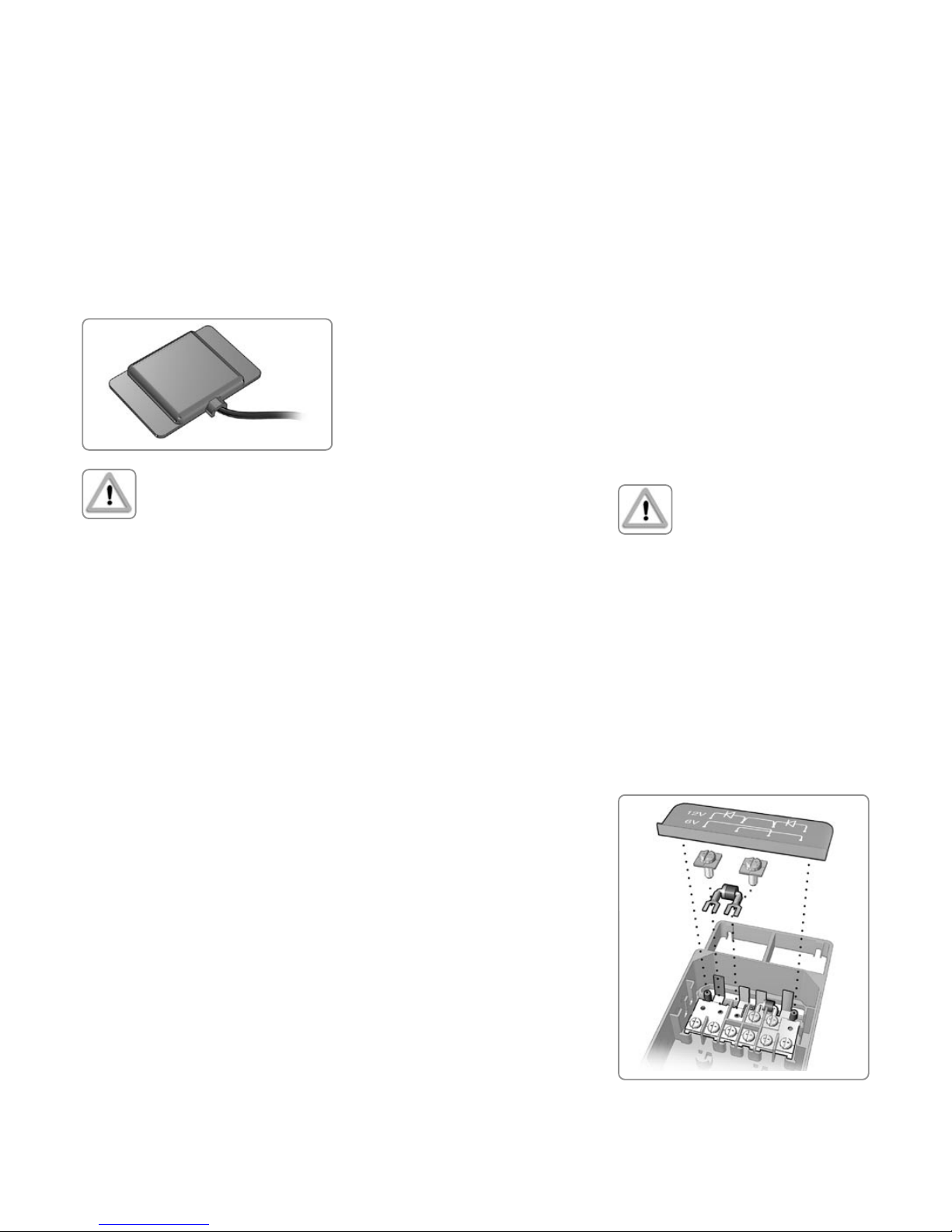
Testing and replacing bypass diodes
ProCharger™-CR junction box
The bypass diodes are located underneath a
protective cover. The connections for 6-V and
12-V operation are shown on this cover.
} Lift off the cover by gently pulling up a
corner of the cover with your finger.
} Remove the diodes by loosening the fas-
tening screws. Note the orientations of the
polarity markings on the diodes.
Protect yourself against electrical shocks
while commissioning and maintaining the
solar power system. Refer to the precautions
at the beginning of the ‘Electrical Installation’
section.
Testing, commissioning
and troubleshooting
Test all electrical and electronic components
of your system before commissioning it.
Follow the instructions in the guides supplied
with the components and equipment. Systems
having a DC voltage greater than 120 V and
systems coupled to the mains grid must be
tested and formally approved by authorised
technical specialists.
Testing modules connected in series before
they are connected to the system
} Check the open-circuit voltage of every
series circuit. The measured value should
correspond to the sum of the open-circuit
voltages of the individual modules. You
will find the rated voltage in the technical
specifications of the type of module used.
If the measured value is significantly lower
than the expected value, please proceed
as described under ‘Troubleshooting an
excessively low voltage’.
} Check the short-circuit current of every
series circuit with direct solar illumina-
tion. You will find the rated current in
the technical specifications of the type of
module used. The measured value can
vary significantly, depending on weather
conditions, the time of day and shading of
the module.
Troubleshooting an excessively
low voltage
Typical causes of this problem are improper
connections at the terminals and defective
bypass diodes.
} First, check all wiring connections.
} Check the open-circuit voltage of each
module:
} Fully cover the modules with an opaque
material.
} Disconnect the wiring at both terminals
of the modules.
} Remove the opaque material from the
module to be checked and measure the
open-circuit voltage at its terminals. If the
measured voltage is only half the rated
value, this indicates a defective bypass
diode. Refer to ‘Testing and replacing
bypass diodes’.
Modules with permanently attached cables
can only be checked at the open end of the
cable after it has been disconnected.

13
Replacing a soldered bypass-diode in a ProCharger™-CR-junction box
Replacing a bypass-diode in
a Spelsberg-junction box
} Check the conductivity of the diodes. They
should conduct electricity when the test
leads are connected in one direction and
show a high resistance in the other direc-
tion. If a diode conducts in both direc-
tions, it is defective.
} Replace a defective diode with a diode of
the same type, and ensure that its polarity
marking is oriented the same way as the
original diode.
} Finally, check the open-circuit voltage of
the module and replace both covers.
ProCharger™-S junction box
} Open the cover and remove the diodes by
cutting their leads with a wire cutter. Note
the orientations of the polarity markings
on the diodes.
} Check the conductivity of the diodes. They
should conduct electricity when the test
leads are connected in one direction and
show a high resistance in the other direc-
tion. If a diode conducts in both direc-
tions, it is defective.
} Replace a defective diode with a diode of
the same type, and ensure that its polarity
marking is oriented the same way as the
original diode. Solder the leads of the
diode to the contacts.
} Finally, check the open-circuit voltage of
the module and close the cover.
Spelsberg junction box
} Open the cover, and remove the diodes
by pressing on each terminal with a small
flat-blade screwdriver and extracting the
diode lead. Note the orientations of the
polarity markings on the diodes.
} Check the conductivity of the diodes. They
should conduct electricity when the test
leads are connected in one direction and
show a high resistance in the other direc-
tion. If a diode conducts in both direc-
tions, it is defective.
} Replace a defective diode with a diode of
the same type, and ensure that its polarity
marking is oriented the same way as the
original diode.
} Finally, check the open-circuit voltage of
the module and close the cover.
Disclaimer of Liability
Since the use of this manual and the condi-
tions or methods of installation, operation,
use and maintenance of the photovoltaic (PV)
product are beyond Shell Solar‘s control,
Shell Solar does not assume responsibility
and expressly disclaims liability for loss,
damage, or expense arising out of or in any
way connected with such installation, opera-
tion, use or maintenance.
No responsibility is assumed by Shell Solar
for any infringement of patents or other
rights of third parties, which may result from
use of the PV product. No license is granted
by implication or otherwise under any patent
or patent rights.
The information in this manual is based on
Shell Solar‘s knowledge and experience and
is believed to be reliable; but such informa-
tion including product specifications (without
limitations) and suggestions do not constitute
a warranty, expressed or implied. Shell Solar
reserves the right to make changes to this
manual, the PV product, the specifications,
or product information sheets without prior
notice.

1. Limited Product Warranty - Two Year Repair,
Replacement or Refund Remedy
Shell Solar B.V. having its registered office at Amsterdam,
the Netherlands (“Shell Solar”) warrants its Photovoltaic
modules (“PV-modules”), including field replaceable DC
connector cable assemblies, to be free from defects in
materials and workmanship under normal, application,
installation, use and service conditions. If the PV-modules
fail to conform to this warranty, then for a period ending
twenty-four (24) months from date of sale to the original
end-customer (“the Customer”), Shell Solar will, at its
option, either repair or replace the product, or refund the
purchase price as paid by the Customer (“Purchase Price”).
The repair, replacement or refund remedy shall be the sole
and exclusive remedy provided under the Limited Product
Warranty and shall not extend beyond the twenty-four (24)
month period set forth herein. This Limited Product Warranty
does not warrant a specific power output, which shall be
exclusively covered under clause 2 hereinafter (Limited Peak
Power Warranty).
2. ‘Limited Peak Power Warranty’ - Limited Remedy
A: 10 years
For the PV-modules (excluding the inverter/ converter)
ST5, ST10, ST20, ST36, ST40, S10, S25, and S36 Shell
Solar additionally warrants: If, within ten (10) years from
date of sale to the Customer any PV-module(s) exhibits a
power output less than 90% of the minimum Peak Power
at STC as specified at the date of delivery in Shell Solar’s
Product Information Sheet, provided that such loss in power
is determined by Shell Solar (at its sole and absolute
discretion) to be due to defects in material or workmanship,
Shell Solar will replace such loss in power by either
providing to the Customer additional PV-modules to make
up such loss in power, or by repairing or replacing the
defective PV-module(s), or by refunding the Purchase Price
taking into account a yearly depreciation of ten (10)% of the
Purchase Price, at the option of Shell Solar.
B: 20 years
For the PV-modules (excluding the inverter/ converter)
S60, S65, S70-C, S75-C, S105-C and S115-C Shell
Solar additionally warrants: If, within (a) the first ten (10)
years from date of sale to the Customer, any PV-module(s)
exhibits a power output less than 90% of the minimum Peak
Power at STC1 as specified at the date of delivery in Shell
Solar’s Product Information Sheet, or (b), within a period of
twenty (20) years from date of sale to the Customer any
PV-module(s) exhibits a power output less than 80% of the
minimum Peak Power at STC1, provided that such loss in
power is determined by Shell Solar (at its sole and absolute
discretion) to be due to defects in material or workmanship,
Shell Solar will replace such loss in power by either
providing to the Customer additional PV-modules to make
up such loss in power, or by repairing or replacing the
defective PV-module(s), or by refunding the Purchase Price
taking into account a yearly depreciation of five (5)% of the
Purchase Price, at the option of Shell Solar.
C: 25 years
For the PV-modules (excluding the inverter/ converter)
SM46, SM50, SM50-H, SM55, SM100-12, SM110-12,
SM100-24, SM100-24C, SM110-24, SM110-24C, SP65,
SP70, SP75, SP130, SP130-C, SP140, SP140-C, SP150,
SP150-C, SQ70, SQ75, SQ80, SQ140-C, SQ150-C and
SQ160-C Shell Solar additionally warrants: If, within (a) the
first ten (10) years from date of sale to the Customer, any
PV-module(s) exhibits a power output less than 90% of the
minimum Peak Power at STC1 as specified at the date of
delivery in Shell Solar’s Product Information Sheet, or (b),
within a period of twenty-five (25) years from date of sale to
the Customer any PV-module(s) exhibits a power output less
than 80% of the minimum Peak Power at STC1, provided
that such loss in power is determined by Shell Solar (at its
sole and absolute discretion) to be due to defects in material
or workmanship, Shell Solar will replace such loss in power
by either providing to the Customer additional PV-modules
to make up such loss in power, or by repairing or replacing
the defective PV-module(s), or by refunding the Purchase
Price taking into account a yearly depreciation of four (4)%
of the Purchase Price, at the option of Shell Solar.
The remedies set forth in this clause 2 shall be the sole and
exclusive remedies provided under the Limited Peak Power
Warranty.
3. Exclusions and limitations
A. Warranty claims must in any event be filed within the
applicable Warranty period.
B. The Limited Warranties do not apply to any PV-modules
which in Shell Solar’s absolute judgement have been
subjected to:
- misuse, abuse, neglect or accident;
- alteration, improper installation or application;
- non-observance of Shell Solar’s installation-, users- and
maintenance instructions;
- repair or modifications by someone other than an
approved service technician of Shell Solar;
- power failure surges, lighting, flood, fire, accidental
breakage or other events outside Shell Solar’s control.
C. The Limited Warranties do not cover any transportation
costs for return of the PV-modules, or for reshipment of
any repaired or replaced PV-modules, or cost associated
with installation, removal or reinstallation of the PV-
modules.
D. When used in non-land based applications the Limited
Peak Power Warranty, applying to any of the PV-modules
shall be limited to ten (10) years as per the provisions of
clause 2A hereof.
E. Warranty claims will not be honoured if the type or serial
number of the PV-modules have been altered, removed
or made illegible.
4. Limitation of Warranty Scope
THE LIMITED WARRANTIES SET FORTH HEREIN ARE
EXPRESSLY IN LIEU OF AND EXCLUDE ALL OTHER EXPRESS
OR IMPLIED WARRANTIES, INCLUDING BUT NOT LIMITED
TO WARRANTIES OF MERCHANTABILITY AND OF FITNESS
FOR PARTICULAR PURPOSE, USE, OR APPLICATION, AND
ALL OTHER OBLIGATIONS OR LIABILITIES ON THE PART
OF SHELL SOLAR, UNLESS SUCH OTHER WARRANTIES,
OBLIGATIONS OR LIABILITIES ARE EXPRESSLY AGREED
TO IN WRITING SIGNED AND APPROVED BY SHELL
SOLAR. SHELL SOLAR SHALL HAVE NO RESPONSIBILITY
OR LIABILITY WHATSOEVER FOR DAMAGE OR INJURY
TO PERSONS OR PROPERTY, OR FOR OTHER LOSS OR
INJURY RESULTING FROM ANY CAUSE WHATSOEVER
ARISING OUT OF OR RELATED TO THE PRODUCT,
INCLUDING, WITHOUT LIMITATION, ANY DEFECTS
IN THE MODULE, OR FROM USE OR INSTALLATION.
UNDER NO CIRCUMSTANCES SHALL SHELL SOLAR BE
LIABLE FOR INCIDENTAL, CONSEQUENTIAL OR SPECIAL
DAMAGES, HOWSOEVER CAUSED. LOSS OF USE,
LOSS OF PROFITS, LOSS OF PRODUCTION, LOSS OF
REVENUES ARE THEREFORE SPECIFICALLY BUT WITHOUT
LIMITATION EXCLUDED.
SHELL SOLAR’S AGGREGATE LIABILITY, IF ANY, IN
DAMAGES OR OTHERWISE, SHALL NOT EXCEED THE
INVOICE VALUE AS PAID BY THE CUSTOMER, FOR THE
UNIT OF PRODUCT OR SERVICE FURNISHED OR TO BE
FURNISHED, AS THE CASE MAY BE, WHICH IS THE
SUBJECT OF CLAIM OR DISPUTE.
5. Obtaining Warranty Performance
If the Customer feels he/she has a justified claim covered
by this Limited Warranty, he/she must immediately notify the
(a) dealer, who sold the PV-modules, or (b) any authorised
Shell Solar distributor, of the claim in writing, or (c) send
such notification to Shell Solar (P.O. Box 38000, 1030
BN Amsterdam, the Netherlands) directly. Together with the
notification Customer should enclose evidence of the date
of sale on which the Solar Products have been purchased. If
applicable, Customer’s dealer or distributor will give advice
on handling the claim. If further assistance is required,
Customer is invited to write Shell Solar for instructions. The
return of any PV-modules will not be accepted unless prior
written authorisation has been given by Shell Solar.
6. Severability
If a part, provision or clause of this Limited Warranty, or
the application thereof to any person or circumstance, is
held invalid, void or unenforceable, such holding shall not
affect and shall leave all other parts, provisions, clauses or
applications of the Limited Warranty, and to this end such
other parts, provisions, clauses or applications of this Limited
Warranty shall be treated as severable.
7. Disputes
No action, regardless of form, arising out of or in any way
connected with this Limited Warranty, may be brought by
the Customer more than one (1) year after the cause of
action has accrued.
8. Various
The repair or replacement of the PV-modules or the supply
of additional PV-modules, does not cause the beginning
of new warranty terms, nor shall the original terms of this
Limited Warranty be extended. Any replaced PV-modules
shall become the property of Shell Solar. Shell Solar has
the right to deliver another type of PV-module (different in
size, colour, shape and/or power) in case Shell Solar
discontinued producing the PV-module in question at the
time of the claim.
In the event that any of the PV-modules purchased by
the Customer are not listed in this Limited Warranty, the
Customer should contact Shell Solar for further information
regarding the applicable warranties, if any.
9. Force Majeure
Shell Solar shall not be in any way be responsible or liable
to the Customer or any third-party arising out of any non-
performance or delay in performance of any terms and
conditions of sale, including this Limited Warranty, due
to acts of God, war, riots, strikes, unavailability of suitable
and sufficient labour, material, die, or capacity or technical
or yield failures and any unforeseen event beyond its
control, including, without limitations, any technological or
physical event or condition which is not reasonably known
or understood at the time of the sale of the PV-modules or
the claim.
1
“Peak Power” is the power in watt peak that a PV-module
generates in its maximum power point. “STC” are as
follows (a) light spectrum of AM 1.5, (b) an irradiation
of 1,000 W per m² and (c) a cell temperature of 25
degrees Centigrade. The measurements are carried out in
accordance with IEC60904 as tested at the junction box
terminals per the calibration and testing standards of Shell
Solar valid at the date of manufacture of the PV-modules.
Shell Solar’s calibration standards shall be in compliance
with the standards applied by international institutions
accredited for this purpose.
SHELL SOLAR LIMITED WARRANTY FOR PV-MODULES
(“Limited Warranty”) – (Excluding U.S.)
General Version excluding U.S. valid as from 1 August 2003
14
15

1. Limited Product Warranty – Two Year Repair,
Replacement or Refund Remedy
Shell Solar Industries LP with offices at 4650 Adohr
Lane, Camarillo, CA 93012 (“Shell Solar”) warrants
its Photovoltaic modules (“PV-modules”), including field
replaceable DC connector cable assemblies, to be free
from defects in materials and workmanship under normal,
application, installation, use and service conditions. If the
PV-modules fail to conform to this warranty, then for a period
ending twenty-four (24) months from date of sale to the
original end-customer (“the Customer”), Shell Solar will, at
its option, either repair or replace the product, or refund the
purchase price as paid by the Customer (“Purchase Price”).
The repair, replacement or refund remedy shall be the sole
and exclusive remedy provided under the Limited Product
Warranty and shall not extend beyond the twenty-four (24)
month period set forth herein. This Limited Product Warranty
does not warrant a specific power output, which shall be
exclusively covered under clause 2 hereinafter (Limited Peak
Power Warranty).
2. ‘Limited Peak Power Warranty’ – Limited Remedy
A: 10 years
For the PV-modules (excluding the inverter/converter) ST5,
ST10, ST20, ST36, and ST40 Shell Solar additionally
warrants:
If, within ten (10) years from date of sale to the Customer
any PV-module(s) exhibits a power output less than 90% of
the minimum Peak Power at STC1 as specified at the date of
delivery in Shell Solar’s Product Information Sheet, provided
that such loss in power is determined by Shell Solar (at its
sole and absolute discretion) to be due to defects in material
or workmanship, Shell Solar will replace such loss in power
by either providing to the Customer additional PV-modules
to make up such loss in power, or by repairing or replacing
the defective PV-module(s), or by refunding the Purchase
Price taking into account a yearly depreciation of ten (10)%
of the Purchase Price, at the option of Shell Solar
B: 25 years
For the PV-modules (excluding the inverter/ converter),
SM50-H, SM55, SM110-12P, SM110-24P, SP70, SQ75,
SP75, SQ80, SP140-P/PC, SP150-P/PC, SQ150-P/PC
and SQ160-P/PC Shell Solar additionally warrants:
If, within (a) the first ten (10) years from date of sale to the
Customer, any PV-module(s) exhibits a power output less
than 90% of the minimum Peak Power at STC1 as specified
at the date of delivery in Shell Solar’s Product Information
Sheet, or (b), within a period of twenty-five (25) years from
date of sale to the Customer any PV-module(s) exhibits a
power output less than 80% of the minimum Peak Power at
STC1, provided that such loss in power is determined by
Shell Solar (at its sole and absolute discretion) to be due to
defects in material or workmanship, Shell Solar will replace
such loss in power by either providing to the Customer
additional PV-modules to make up such loss in power, or
by repairing or replacing the defective PV-module(s), or by
refunding the Purchase Price taking into account a yearly
depreciation of four (4)% of the Purchase Price, at the option
of Shell Solar.
The remedies set forth in this clause 2 shall be the sole and
exclusive remedies provided under the Limited Peak Power
Warranty.
3. Exclusions and limitations
A. Warranty claims must in any event be filed within the
applicable Warranty period.
B. The Limited Warranties do not apply to any PV-modules
which in Shell Solar’s absolute judgement have been
subjected to:
- misuse, abuse, neglect or accident;
- alteration, improper installation or application;
- non-observance of Shell Solar’s installation-, users- and
maintenance instructions;
- repair or modifications by someone other than an
approved service technician of Shell Solar;
- power failure surges, lighting, flood, fire, accidental
breakage or other events outside Shell Solar’s control.
C. The Limited Warranties do not cover any transportation
costs for return of the PV-modules, or for reshipment of
any repaired or replaced PV-modules, or cost associated
with installation, removal or reinstallation of the PV-
modules.
D. When used in non-land based applications the Limited
Peak Power Warranty, applying to any of the PV-modules
shall be limited to ten (10) years as per the provisions of
clause 2A hereof.
E. Warranty claims will not be honored if the type or serial
number of the PV-modules have been altered, removed
or made illegible.
4. Limitation of Warranty Scope
THE LIMITED WARRANTIES SET FORTH HEREIN ARE
EXPRESSLY IN LIEU OF AND EXCLUDE ALL OTHER EXPRESS
OR IMPLIED WARRANTIES, INCLUDING BUT NOT LIMITED
TO WARRANTIES OF MERCHANTABILITY AND OF FITNESS
FOR PARTICULAR PURPOSE, USE, OR APPLICATION, AND
ALL OTHER OBLIGATIONS OR LIABILITIES ON THE PART
OF SHELL SOLAR, UNLESS SUCH OTHER WARRANTIES,
OBLIGATIONS OR LIABILITIES ARE EXPRESSLY AGREED
TO IN WRITING SIGNED AND APPROVED BY SHELL
SOLAR. SHELL SOLAR SHALL HAVE NO RESPONSIBILITY
OR LIABILITY WHATSOEVER FOR DAMAGE OR INJURY
TO PERSONS OR PROPERTY, OR FOR OTHER LOSS OR
INJURY RESULTING FROM ANY CAUSE WHATSOEVER
ARISING OUT OF OR RELATED TO THE PRODUCT,
INCLUDING, WITHOUT LIMITATION, ANY DEFECTS
IN THE MODULE, OR FROM USE OR INSTALLATION.
UNDER NO CIRCUMSTANCES SHALL SHELL SOLAR BE
LIABLE FOR INCIDENTAL, CONSEQUENTIAL OR SPECIAL
DAMAGES, HOWSOEVER CAUSED. LOSS OF USE,
LOSS OF PROFITS, LOSS OF PRODUCTION, LOSS OF
REVENUES ARE THEREFORE SPECIFICALLY BUT WITHOUT
LIMITATION EXCLUDED.
SHELL SOLAR’S AGGREGATE LIABILITY, IF ANY, IN
DAMAGES OR OTHERWISE, SHALL NOT EXCEED THE
INVOICE VALUE AS PAID BY THE CUSTOMER, FOR THE
UNIT OF PRODUCT OR SERVICE FURNISHED OR TO BE
FURNISHED, AS THE CASE MAY BE, WHICH IS THE
SUBJECT OF CLAIM OR DISPUTE.
SOME STATES DO NOT ALLOW LIMITATIONS ON IMPLIED
WARRANTIES OR THE EXCLUSION OF DAMAGES SO
THE ABOVE LIMITATIONS OR EXCLUSIONS MAY NOT
APPLY TO YOU.
5. Obtaining Warranty Performance
If the Customer feels he/she has a justified claim covered
by this Limited Warranty, he/she must immediately notify the
(a) dealer, who sold the PV-modules, or (b) any authorized
Shell Solar distributor, of the claim in writing, or (c) send
such notification to Shell Solar Industries LP (P.O Box
6032, Camarillo, CA 93011) directly. Together with the
notification Customer should enclose evidence of the date
of sale on which the Solar Products have been purchased. If
applicable, Customer’s dealer or distributor will give advice
on handling the claim. If further assistance is required,
Customer is invited to write Shell Solar for instructions. The
return of any PV-modules will not be accepted unless prior
written authorization has been given by Shell Solar.
6. Severability
If a part, provision or clause of this Limited Warranty, or
the application thereof to any person or circumstance, is
held invalid, void or unenforceable, such holding shall not
affect and shall leave all other parts, provisions, clauses or
applications of this Limited Warranty, and to this end such
other parts, provisions, clauses or applications of this Limited
Warranty shall be treated as severable.
7. Disputes
No action, regardless of form, arising out of or in any way
connected with this Limited Warranty, may be brought by
the Customer more than one (1) year after the cause of
action has accrued.
THIS LIMITED WARRANTY GIVES YOU SPECIFIC LEGAL
RIGHTS; YOU MAY ALSO HAVE OTHER RIGHTS THAT
VARY FROM STATE TO STATE.
8. Various
The repair or replacement of the PV-modules or the supply
of additional PV-modules, does not cause the beginning
of new warranty terms, nor shall the original terms of this
Limited Warranty be extended. Any replaced PV-modules
shall become the property of Shell Solar. Shell Solar has
the right to deliver another type of PV-module (different
in size, color, shape and/or power) in case Shell Solar
discontinued producing the PV-module in question at the
time of the claim.
9. Force Majeure
Shell Solar shall not be in any way be responsible or liable
to the Customer or any third-party arising out of any non-
performance or delay in performance of any terms and
conditions of sale, including this Limited Warranty, due
to acts of God, war, riots, strikes, unavailability of suitable
and sufficient labor, material, die, or capacity or technical
or yield failures and any unforeseen event beyond its
control, including, without limitations, any technological or
physical event or condition which is not reasonably known
or understood at the time of the sale of the PV-modules or
the claim.
1
“Peak Power” is the power in watt peak that a PV-module
generates in its maximum power point. “STC” are as
follows (a) light spectrum of AM 1.5, (b) an irradiation
of 1,000 W per m² and (c) a cell temperature of 25
degrees Centigrade. The measurements are carried out in
accordance with IEC60904 as tested at the junction box
terminals per the calibration and testing standards of Shell
Solar valid at the date of manufacture of the PV-modules.
Shell Solar’s calibration standards shall be in compliance
with the standards applied by international institutions
accredited for this purpose.
SHELL SOLAR LIMITED WARRANTY FOR PV-MODULES
(“Limited Warranty”) – (U.S.)
General U.S. Version valid as of 1 August 2003
14
15

Ordering Number ShSo/Int/MGA/0903
Environmentally friendly – paper bleached without
chlorine. Printed in Germany
Shell Solar B.V.
PO Box 38000
1030 BN
Amsterdam
The Netherlands
Fax: +31-20-630-2211
Shell Solar Industries
4650 Adohr Lane
Camarillo, CA 93011
United States
Fax: +1-805-388-6395
Shell Solar Pte. Ltd.
72 Bendemeer Road
Hiap Huat House #07-01
Singapore 339941
Fax: +65-6842-3887
Status 09/03 – Subject to modifications – © 2003 Shell Solar GmbH
Shell modules are recyclable.
Internet: www.shell.com/solar
Shell Solar GmbH
Domagkstrasse 11
80807 Munich
Germany
Fax: +49-89-636-59140
Table of contents
Popular Solar Panel manuals by other brands


STI
STI FKF 200 Series Assembly instructions

IBC SOLAR
IBC SOLAR TopFix 200 installation manual

CanadianSolar
CanadianSolar CS6R-MB-AG installation manual

Qcells
Qcells Q.PEAK DUO-G5 series Installation and operation manual

evergreensolar
evergreensolar Cedar Line Operation manual

Go Power
Go Power GP-PSK-90 user manual

Qcells
Qcells Q.PEAK DUO-G5.X Installation and operation manual

GOAL ZERO
GOAL ZERO Nomad 7 Plus user guide

evergreensolar
evergreensolar ES-A-190 Safety, installation, and operation manual

GOAL ZERO
GOAL ZERO Nomad 20 user manual

GOAL ZERO
GOAL ZERO Nomad 20 user guide

Sunsystem
Sunsystem VTC Series Installation and operation manual