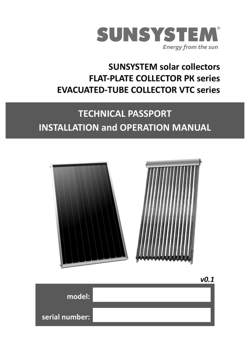
Sunsystem VTC Series User manual

TECHNICAL PASSPORT
INSTALLATION and OPERATION MANUAL
SUNSYSTEM Solar Collectors
EVACUATED-TUBE COLLECTOR - VTC Series
Support system for Flat roof, Inclined roof and Façade
Model: .............................................................
Serial Number: .................................................
v. 0.1.1

2-EN
INSTALLATION and OPERATION MANUAL
Table of contents
1
Explanation of symbols and safety instructions
3
1.1. Explanation of symbols
3
1.2. Requirements to collector installation place
3
1.2.1. Instructions to collector installer
3
1.2.2. Instructions to installation user
4
2
Description of evacuated-tube collector VTC
5
3
Packing and Transport
6
4
Delivery
6
5
Installation of VTC collector and the support system
7
5.1 Installation of collector VTC. Support system for Flat roof
8
5.2 Installation of collector VTC. Support system for Inclined roof
9
5.3. Installation of collector VTC. Support system for Facade
11
5.4. Connecting multiple collector series
12
6
Connect the collector to the Hot Water System and / or Central Heating
13
6.1. Protecting collector of lightning, hail, frost, overheating
13
6.2. Manifold connections
13
6.3. Stagnation temperature
14
6.4. Mounting the temperature sensor vacuum tube collector VTC
15
6.5. Installation of safety valve for temperature
15
6.6. Pressure. Temperature control. Venting
15
6.7. Filling of the solar system
15
6.8. Connection diagrams
16
7
Commissioning
18
8
Prevention and maintenance of the collectors
18
9
Warranty terms
19
10
Technical characteristics
21
11
Recycling and disposal
23

3-EN
INSTALLATION and OPERATION MANUAL
1. Explanation of symbols and safety instructions
1.1. Explanation of symbols
CAUTION! - Important recommendation or warning concerning safety conditions during installation
and operation of the solar collector.
DANGER! - fault or improper use may cause injury or be hazardous to life of humans or animals.
INFORMATION –Important information on the proper operation of the product.
1.2. Requirements to solar collector installation place
This manual contains important information for the safe and correct installation, start-up and trouble-free
operation and maintenance of the solar collector.
The solar collector can be used to produce domestic hot water and support of space heating system only
in the manner described in this manual. The application and any other was the area of operation is not
recommended by the manufacturer and is not responsible for the occurrence of defects or failures.
Note the collector type data on the factory rating label and the technical data (see 12) in order to ensure
proper operation of the product.
1.2.1. Instructions to collector installer
During installation and operation, the country-specific requirements and regulations must be
observed:
• Local construction regulations on installation on building –mass of the system to comply with the
building structure.
The support system and the collector must be installed and secured in accordance with local
regulations and standards for wind resistance and / or snow mass-load.
• Regulations and norms concerning safety installation and operation of solar collectors - protective
gloves, eyewear should be used; make sure collector is securely attached to the building.
Use only original SUNSYSTEM parts.
DANGER of structure damage / injury from fall. The weight of collector/collectors must
comply with the building structure, namely the distribution of weight; strong and secure
fixation of collector support to the roof/façade of building. We recommend the securing of the
area during installation and the construction of roof barriers protecting against downslide of
snow mass. Failure to comply with these recommendations can lead to fatal consequences.

4-EN
INSTALLATION and OPERATION MANUAL
Risk of injury, burn upon installation and maintenance of solar collectors:
- On contact with broken glass/vacuum tube
- On contact with collector in function because of its high temperature.
We recommend the use of protective equipment, gloves, eyewear (goggles), and clothing.
Installation and maintenance of collectors must be carried out in the early morning hours.
When the collector is still cold you can cover it with tarpaulin to avoid its heating by direct
sunlight.
FIRE HAZARD through contact of accumulated waste (dry leaves, plastic bags, paper) with the
hot parts of the collectors. We recommend the regular inspection and cleaning of collector
installation sites.
DANGER of slipping, fall. In most cases, collectors are installed in hardly accessible and
dangerous places. We recommend that installation and service maintenance be carried out
by authorized service technicians observing all safety measures.
1.2.2. Instructions to installation user
CAUTION! Danger of injury / damage of system due to incompetent operation.
The solar collector must be serviced only by persons familiar with the operation manual.
Structural changes to collector by user can cause damage to equipment or injury.
Safety rules for user operation:
- The solar collector can be used to produce hot water and support the heating system only in the manner
described in this manual.
- Installation and maintenance must be performed by a technician / service shop authorized for such
operations.

5-EN
INSTALLATION and OPERATION MANUAL
2. Description of Evacuated-tube collector - VTC
2.1. Evacuated tube. Absorber coating.
Diagram 1
Evacuated tubes are two concentrically positioned borosilicate glass tubes
enclosing a gap of evacuated air. The internal glass tube is coated on its
external surface with an environmentally friendly, highly selective layer and
thus functioning as an efficient absorber.
2.2. Heat-carrier pipe system
Diagram 2
Copper heat-carrier tubes type Heat Pipe TU 1. The pipe
system is manufactured with a minimum number of
welds for perfect air-tightness and reduced deposits
accumulation possibility.
Heat Pipe technology is characterized by its high
efficiency:
improved heat-absorbing capacity of collector, low heat
losses and stable performance in harsh climate conditions.
Diagram 3
Heat carrier fluid runs from evacuated tubes to the manifold pipe and hence
the system.
Both outlets of Manifold pipe can be connected as heat-carrier input or
output in any direction.
2.3. Temperature sensor can be mounted left or right, depending on the
position of the heat-carrier outlet.
2.4. Heat transfer plates resistant to high temperatures of stagnation.
2.5. High-efficiency insulation of collector pipe.
2.6. Durable construction made of resistant to harsh climatic conditions, materials.

6-EN
INSTALLATION and OPERATION MANUAL
4. Packing and Transport
During transport and installation, depending on the weight, suitable safety devices should be used in
accordance with Directive 2006/42/EC. When transporting items weighing more than 30 kg, the use of
pallet jack, fork truck or other hoisting devices is a must.
We recommend transportation of collector to installation site in its packaging. Each glass tube of collector
as well as collector manifold are individually packed in separate carton boxes.
5. Delivery of collector
Inspect the integrity of the packaging upon delivery.
Check whether all components have been delivered to you.
-Check to assure that evacuated tubes are all intact and the bottom of each tube is still silver-
colored. If a tube has a white clear bottom, that means it is damaged and should be replaced. As
soon as the evacuated tubes are removed from the box, please put on the rubber tube caps, found
inside the manifold box. This will protect the bottom tip of the glass tube from breaking on impact.
-Both outlets of Manifold pipe are fit with plastic protectors. Remove inlet/outlet pipe plastic
protectors before connecting collectors to system.
-Do not take out or expose the tubes to sunlight during installation, otherwise the inner tube and
heat transfer fin will become very hot.
Delivery includes:
1) Collector.
2) Technical passport. User manual.
3) Warranty card.
If any of the above items are missing, contact your supplier.
It may be necessary to purchase bolts or other fasteners to suit the installation surface.
Delivery pack of Evacuated-tube collector VTC includes:
Diagram 4
А- Manifold - 1pcs.
В –Mounting sheet - 4 pcs.
C –Press pad –4 pcs.
D- Тube holder -15/20/30 pcs.
E- Heat conduction glue –1 pcs.
F- Front track - 2 pcs.
G- Wood screws 4 pcs.
H –Bottom track –1 pcs.
J –Bolts / Болтове– 13 pcs.
K –Silicon pad–4 pcs.
M –Heat pipe vacuum tube–15/20/30
pcs.

7-EN
INSTALLATION and OPERATION MANUAL
5. Installation
Must be performed by an authorized service technician/service shop for such operations.
DANGER of slipping. In most cases, collectors are installed in hardly accessible and dangerous
places. We recommend that installation and service maintenance be carried out by an
authorized service technician observing all safety measures.
Danger of burns during installation and maintenance of solar collector:
We recommend the use of protective equipment, gloves, eyewear (goggles), and clothing.
Installation and servicing of collectors should be carried out in early morning hours. While the
collectors are still cold you can cover them with tarpaulin to avoid their heating by direct
sunlight.
Recommendations:
The collectors can be installed in places where the values for:
wind load Vm (mean wind speed) does not exceed 150 km/h and
snow loads Sk (weight of snow mass) does not exceed 1,25 kN/m,
according to ENV 1991-1-3 and 1991-1-4.
Recommended orientation: Facing the equator
Recommended mounting angle: 10 ° ÷ 90 ° according to collector application.
Collector application
Recommended mounting angle
Domestic Hot Water /DWG+pool
30°÷45°
Domestic Hot Water + Central Heating /
DWG+CH+pool
45°÷60°
Avoid shading from neighboring buildings, trees, collectors etc.
The applicable minimum clearances in your country may
differ from the ones specified bellow.
Please, consult your installer. The minimum distance
from the collector construction to roof end must be at
least 1 meter;
The collector should be positioned as close as possible to
the DWG /CH consumer to minimize heat loss. Efficiency
heat transfer pipes insulation is recommended.
Collector support must be grounded to the buiding
grounding system.
Installation of collector on a special support must be in
one single plane.
Diagrаm 5

8-EN
INSTALLATION and OPERATION MANUAL
Evacuated tube collectors are mounted placing the manifold on the top and the rubber protectors in the
bottom part. Such collectors have vertical orientation.
Diagram 6
Collectors VTC type are mounted on specially designed support systems, adapted to different roof slopes.
and facade.
Diagram 7
5.1. Flat roof VTC type collector installation
Diagram 8
Installation is carried out by at least two people.
We recommend consulting with a roofing expert.
Fix the support onto the roof as indicated in the Collector Support
Installation Instructions. Adjust the support angle as needed.
Onto the support stand mount the collector frame with manifold and
pipe holders. Fix the collector to support using the clamping clips. Make
sure all connections are properly secured and will not come loose under
harsh weather conditions.
Evacuated tubes are installed last, after the system has been connected
and tested for leakage.

9-EN
INSTALLATION and OPERATION MANUAL
5.2. Inclined roof VTC type collector installation
Installation is carried out by at least two people.
We recommend consulting with a roofing expert.
Diagram 9
Step 1. Install the four fixing straps
B to the roof using the screws G.
Diagram 10
Step 2. Put alongside and parallel to
each other the two side rails F.
For each rail put two silicone pads K,
in places where the bar rests on the
roof tile.
Install the two side rails F to fixing
straps B. Use the screws and
therefore provided orifices in the
rails.
Diagram 11

10-EN
INSTALLATION and OPERATION MANUAL
Step 3. At the bottom of both
side rails F insert bottom rail H
and in the top part - the VTC
collector manifold A. Both
collector manifold A and
bottom rail H must lay
perpendicular to the side rails
F. Fixation orifices of collector
manifold A and bottom rail H
should match the side rails F,
while observing the correct
weight distribution scheme.
Fix A and H to side rails F using
two clamping clips C for each.
In this way the collector
framework is composed.
Diagram 12
Once you have installed the framework and the manifold, put the system together and check
its integrity and correct function. If no leaks are detected, you can install the evacuated
tubes.
Step 4. Take the plastic tube hangers
D. Their number is equal to the
number of pipes. Place them in the
holes on the bottom rail H.
Diagram 13

11-EN
INSTALLATION and OPERATION MANUAL
Step 5. Carefully take evacuated
tube M out of the box. The upper
end of the tube with a silver probe-
like tip must fit inside its designated
nest on manifold, spread beforehand
with the heat-conductive paste (Е)
included in consignment kit. The
lower end of the tube must pass
through tube holder D. Place the
plastic protector on the bottom of
tube M. Carefully screw the
protector onto the holder.
Repeat this until you install all glass
evacuated tubes M.
Diagram 14
5. 3. Installation of VTC type evacuated tube collectors on façade
Installation should be carried out by at least two people. We recommend consulting with a carrier wall
expert.

12-EN
INSTALLATION and OPERATION MANUAL
5.4. Collector array connection
- For connecting several collectors in array, it is necessary to use the flexible pipes between two collectors
because of material expansion upon heating and contraction upon cooling.
Diagram 15
Number of collectors VTC-type in one array:
Model
Number of Collectors
VTC 15
8
VTC 20
7
VTC 30
5
- To prevent shading in two or more rows of collectors, follow the distance L between the rows.
Diagram 16
Collector
mounting
angle
ɑ
Distance L between
the rows, m
25°
4,74
30°
5,18
35°
5,58
40°
5,94
45°
6,26
50°
6,52
55°
6,74
60°
6,90

13-EN
INSTALLATION and OPERATION MANUAL
6. Connecting the collector to Domestic Hot Water/Central Heating system
6.1. Connecting the collector to Domestic Hot Water/Central Heating system
Must be performed by an authorized service technician/service shop for such operations.
Our warranty does not cover damage from extremely strong force majeure acts of nature.
We recommend that damage of collectors be included as a clause in your building insurance.
• Collector protection against lightning. The lightning rod should be 1.5 meter higher and 3 meter
far away from the solar collectors.
• Collector protection against hail, strong wind and snow mass. Each solar collector is tested for
resistance to harsh weather conditions:
- Hail resistance: size up to 25 mm /1” when collector mounting angle is ≥40°.
In areas with frequent hailstorms it is recommended to install a protective net over collectors.
-Strong wind resistance: wind speed up to 120 km/h
In areas with strong, steady winds it is recommended to further strengthen the collector support fixation
to the building structure, as well as frequent inspection to prevent any loosening of connections.
-Snow mass resistance: load up to 30 cm –1.25 kN/m2
In areas with heavy snowfalls it is recommended to further strengthen the collector support fixation to the
building structure, as well as frequent inspection to prevent any loosening of connections.
• Collector protection against frost. To protect the collector against frost (closed loop) Propylene
Glycol PG heat-carrier fluid is recommended.
Relation between Propylene Glycol and water:
PG / Propylene Glycol /: Water
Freezing point
20% : 80%
-7 ℃
30% : 70%
-13 ℃
40% : 60%
-23℃
50% : 50%
-34℃
If you choose water as heat carrier, it is recommended to connect to the system a controller unit
supporting antifreeze function working with water as heat-carrier.
• Collector protection against overheating. If the system is designed to power a central heating
circuit it would produce more hot water than necessary in the summer period. In this case, we
recommend that the system be fitted with a device for heat dissipation or to add more users to the hot
water circuit in the summer (swimming pool or other similar consumers).

14-EN
INSTALLATION and OPERATION MANUAL
6.2. Collector outlets/connections
Upon design of vertical risers it is recommended that the heat carrier flow speed be between
0.5 and 0,8 m/s, and the riser pipes be made of copper.
For example: For collector area 20m2the required flow rate is 1000L/h at a heat-carrier speed of 0,5 m/s
- recommended pipe section is ø28x1 Cu.
We recommend - two and/or more collector fields to be connected using the Tichelmann principle.
When installing the collector it is mandatory that on its highest point an automatic air purge be
installed to facilitate system charging.
Connection of collectors is carried out using Hollander joints.
The use of galvanized pipes and fittings for connecting collectors to water tanks is forbidden due to
electrical corrosion hazard
Fixing the fittings:
Always use two opposing spanners when tightening the compression fittings. Do not twist the
copper pipe (inlet/outlet) as the header maybe damaged.
Tighten with standard length spanners using moderate torque force. Do not overtighten the
fittings.
Flood the circuit with water and check the for leaks at the compression fittings. If leaking then
loosen the fitting completely, and wrap the Teflon plumbing tapes or a suitable sealing
compound.
For several collectors connections, it is necessary to use the flexible pipes between two collectors
because of the Expansion on heating and contraction on cooling.
Heat loss from the piping can be significant and should be taken to insulate any possible points of
heat loss. Ensure the insulation material is tight against the pipeline, inlet and outlet. Using the
silicone sealant to form a water-tight seal on the temperature sensor. The insulation foam should
be protected against the UV. The circulation pump should be also insulated otherwise it could be a
source of heat loss.
6.3. Stagnation temperature
Stagnation refers to the condition that occurs when the pump stops running, due to pump failure, power
blackout, or as a result of a high tank temperature protection feature built into the controller, which turns
the pump off. If a PTRV is installed on collector inlet or outlet the collector will continue to increase in
temperature until the limit of the temperaure relief valve is reached, at which point hot water will be
dumped from the system. If a PTRV is not installed on the collector, steam will form in the header.
Eventually some steam may feed back to the storage tank via the return line.
The PTRV on the tank will open to release pressure or heat as required. Under such conditions the
manifold will normally reach a maximum temperature of around 160/320F.. Generally the heat returning
from the collector in the form of steam is not enough to affect a continued increase in tank temperature
(ie. Heat input <tank heat losses)Under normal use stagnation should rarely occur as a result of pump
stoppage, since power blackouts normally happen during storms and not clear sunny weather. High tank
temperature protection should only occur when hot water is notused for several days (when on holiday),
and only during strong periods of sunlight (summer). If leaving the house for an extended period of time
(more than 2-3days), it is advisable to cover the collector panel or design the system with a heat
dissipation device or alternative use for the heat, thus preventing overheating of the system and collector
stagnation. Stagnation of the solar collector will
NOT damage the solar collector, however insulation used on the piping close to the manifold inlet and
outlet should be able to withstand temperatures of up to 200℃/395F. (Eg. Glass wool or mineral wool-
with an exterior wrap of aluminium foil, thus protecting against the elements).

15-EN
INSTALLATION and OPERATION MANUAL
6.4. Installation of Temperature sensor
The solar collector temperature sensor should be coated with a thick layer of thermal paste and inserted
into the sensor sleeve to the full depth. If the fit is too loose, slide a piece of copper plate or wire in beside
the sensor, Seal the sensor sleeve opening with silicone sealant to prevent water ingress. Ensure that
sensors used on the collector are high temperature rated (up to 250℃/486F), in particular the cable.
6.5. Installation of safety valve (thermostatic or other)
According to safety norms, it is mandatory to install a thermostatic mixing valve. The valve is mounted on
the hot water pipe between DHW storage tank and bathroom/service room, in order to prevent scalding.
Through this valve you can control hot water temperature - below 50℃/122F (temperature is adjustable).
6.6. Pressure control. Temperature control. Relief valve.
Regardless of the installation configuration, pressure release values, expansion vessels and/or other
pressure control devices must be installed. The solar loop should be designed to operate at no
more than 800kPa - PRV may be 850kPa.
(800kPa =8bar=116psi
For installation where mains pressure water is used, the system should ideally be designed to operate at a
pressure of <500kPa, achieved by use of a pressure limiting/reduction value.
For the reliable operation of system, we recommend you check the lever of the pressure and temperature
return valve (PTRV) every six months. The PTRV lever should be raised and dropped gently without effort.
Collector working (operating) pressure should be secured using a pressure relief valve at 6 bars.
An expansion vessel must be mounted in order to take up the extra volume of fluid caused by heat
expansion. Recommended capacity of expansion vessel is 8 ÷ 10 L/m2of VTC type collector area.
To avoid damage to system and heat carrier circuit, all air purge valves must be closed upon purging
of air from the system. This will prevents the release of steam and the penetration of oxygen from
the ambient air.
6.7. Filling of system.
• To prevent overheating, the filling of system must be carried out in the morning or evening in the
absence of direct sunlight.
• Direct use of collector for hot water preparation is not allowed because of the eventual clogging of pipes
over a short time by lime scale deposits.
•Inside collector pipes and risers circulates a certain fluid (water, propylene glycol or Tyfocor of freezing
point corresponding to the requirements of certain installation (see section 6.1 of this manual.)When
using any other heat carrier fluid to fill the collector manufacturer does not take any responsibility for
product warranty.

16-EN
INSTALLATION and OPERATION MANUAL
6.8. Connection diagrams
Must be performed by an authorized service technician/service shop for such operations.
Diagram 17. . Connection of Evacuated-tube collector VTC to solid fuel boiler WBS, combi tank KSC2 and three-way
valve

17-EN
INSTALLATION and OPERATION MANUAL
Diagram 18. Connection of Evacuated-tube collector VTC to solid fuel boiler WBS, solar water tank SON, buffer tank P
and three-way valve

18-EN
INSTALLATION and OPERATION MANUAL
7. Commissioning
Must be performed by an authorized service technician/service shop for such operations.
Before commissioning of solar collector into operation, check:
The air-tightness of all connections
System air purging
Insulation of pipelines: must be UV resistant and temperature shock proof as well as bird- and
rodent-proof in structure.
Electrical connections: controller, pump
8. Damage prevention and service maintenance of collectors
Any changes in design or construction of solar collectors are strictly prohibited. Detection of
such makes warranty null and void. As changes in design and construction shall be
considered the removal of any manufacturer-embedded items, incorporation of additional
components in the collector, replacement of any components with similar or analogues not
explicitly approved by the manufacturer.
8.1 It is recommended that yearly maintenance be carried out by an authorized service. All service
maintenance must be logged on the warranty card.
-Checkup of operating pressure, pump operation, hydraulic connections.
-Checkup of heat carrier fluid, replacement thereof.
8.2. Cleaning of collectors from dust deposits, fallen dry leaves and twigs
Keeping the collector surface clean is a prerequisite for good performance. A dusty collector (due to lack of
rainfall, dusty ambience) can be cleaned up in early morning hours before it is heated by sunlight using:
-Warm water, soap/glass cleaner solution and a soft cloth when the collector is mounted in an
easily accessible and safe place;
-Pressurized water jet when the collector is mounted in a hardly accessible place.
-
8.3. Replacing of broken (damaged) VTC-tube
In any event of broken collector tube it needs to be replaced as quickly as possible. Despite the damaged
tube, the collector can still operate, but its efficiency will drop. Clean broken glass to prevent future
injuries. We recommend that replacement of the broken collector tube be carried out by an authorized
installer / service observing all safety norms.

19-EN
INSTALLATION and OPERATION MANUAL
9. Warranty terms.
Failure to observe the installation and operating requirements described in this manual voids the
warranty.
1. Manufacturing defects and materials guarantee
Manufacturer expressly guarantees that the products it manufactures shall be free from defects in
materials and workmanship which can prevent from normal operation under proper and normal use,
installation and maintenance for the intended functions of the products for a period set out in the
warranty certificate of the respective model of the collector you have bought.
The warranty period begins from the date indicated in the purchase invoice. If a product or any
component thereof is determined to be defective in manufacture or materials. Will repair or replace
the defective component or product.
2.Exclusions and Limitations of Warranty Coverage
2.1. The customer can claim warranty during warranty period of respective product immediately
after any defects have been determined, except for in case of noticeable defects at the moment of
purchase, in which case the customer must make the claim at the shop immediately after noticing
the defect, as it is provided for in the general conditions of sale.
2.2. This warranty certificate is considered void in cases when defects and errors in functioning of
products are caused by:
- Accidents as a result of improper storage, transportation, unsuitable or incorrect use.
- Failure to observe the installation, use, and maintenance instructions set forth in the installation
manual of respective product.
-Improper installation or use as well as changes especially if they are not made by authorized after -
sale service personnel.
-Testing and operation pressures greater than the values established by Manufacturer and set forth
in product manuals.
Freeze, flood, natural disasters or third party actions as well as any interventions into normal
functioning conditions of collectors and Manufacturer control
2.3. The warranty certificate is considered void as well for a collector whose Serial identification
number has been modified, removed or blurred, or cannot be expressly attested.
2.4. Damages in the appearance of products shall not be considered as defects giving right for laying
claim except for those ones which cause problems in functioning or change technical characteristics
of collectors.
2.5. Manufacturer preserves its right, in case of replacement, to deliver another model of collector in
order to fulfill approved warranty claims in case the original model is not being manufactured.
3. Claiming warranty
The customer who has a good reasons to lay a warranty claim, shall proceed as follows:
3.1. Immediately notify in writing to:
- Installer, or Seller;
- Distributor company;
- Manufacturer regional representative office, if any.
For this purpose the claimant shall fill out a claim form; the latter shall be accompanied by the
document proving the purchase of the collector (invoice) with the date of purchase in it.
3.2. After receiving the claim form, Manufacturer considers it and makes decision whether the claim
has grounds or not, and whether the defect is within the scope of the warranty set forth in this
certificate for limited warranty; after which informs the customer as to its decision.
3.3. The return of a product cannot be done without written authorization issued by the Claim
Department.
3.4. If on customer's request, and when there is reason for urgency, the customer demands
immediate replacement of the product he has claimed warranty for, before receiving the decision as

20-EN
INSTALLATION and OPERATION MANUAL
to the claim, said request shall be accompanied by a Purchase requisition from the Commercial
Department. After decision for satisfaction of the claim has been made, the Purchase requisition
mentioned above will be annulled by issuing a receipt for returned goods; with this receipt the
customer can purchase another product with the same price in case the claim has proved grounded.
4. Limitation of liability
а) Manufacturer is not liable before the customer, neither directly nor indirectly, for any non-
fulfillment or delay at applying the warranty obligations which might originate from external
pressure of other circumstances outside Manufacturer
b) The liability of Manufacturer under this Warranty Certificate is limited to the abovementioned
obligations and up to the sum in accordance with the purchase receipt of the product to be claimed;
excluded is any liability for indirect damages such as loss of data at information applications, loss of
production, thermal variations at the service, etc. which do not violate the applicable regulations of
any country concerning product liability.
c) Abovementioned warranty limitations will be applied in any cases, and when they do not violate
the regulations in any country concerning product liability. If this circumstance annuls some of
preceding clauses, annulment will refer only to this clause, while the others will remain valid. In
conclusion, excluded is application of any Regulation pointed out in this Warranty which violates the
Law 23/July 10, 2003 and Directive 1999/44/EU concerning water heaters and their use on the
territory of the EU.
d) Any other warranty right that is not mentioned in this Warranty Certificate is excluded
This manual suits for next models
3
Table of contents
Other Sunsystem Solar Panel manuals
Popular Solar Panel manuals by other brands

Wiedenmann
Wiedenmann Favorit XP Translation of original operating instructions

Steinbach
Steinbach Speedsolar instruction manual

Gasolarxy
Gasolarxy PG-GSP150W quick start guide

Simplicity
Simplicity 1690583 Operator's manual

Kyocera
Kyocera KD205GX-LPU datasheet

Simplicity
Simplicity 1691260 Operator's manual