manuals.online logo
Brands
  1. Home
  2. •
  3. Brands
  4. •
  5. evergreensolar
  6. •
  7. Solar Panel
  8. •
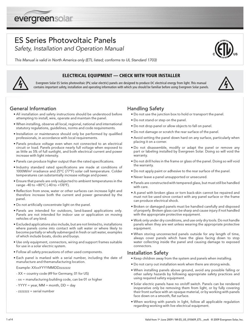
  9. evergreensolar Cedar Line User manual

evergreensolar Cedar Line User manual

138 Bartlett Street, Marlboro, MA 01752 USA
TL: 508.357.2221 FX: 508.229.0747 www.evergreensolar.com
Document #DS20-007024 1 v3.8 rev 2/15/06
EVERGREEN SOLAR
CEDAR LINE™ PHOTOVOLTAIC MODULES
INSTALLATION AND OPERATION MANUAL
WARNING
ELECTRICAL HAZARD
Please read this manual completely before installing or
using an Evergreen Solar Cedar photovoltaic (PV, solar
electric) module. This photovoltaic module produces
electricity when exposed to light. Follow all
applicable electrical safety precautions. Only
qualified personnel should install or perform
maintenance work on this module. Do not damage or
scratch the rear surface of the module. Do not handle
modules when they are wet.
Safety Precautions
Photovoltaic modules produce DC electricity when
exposed to light and therefore can produce an
electrical shock or burn. Modules produce voltage
even when not connected to an electrical circuit or
load. Modules produce nearly full voltage when
exposed to as little as 5% of full sunlight, and both
current and power increase with light intensity. Use
insulated tools and rubber gloves when working with
modules in sunlight.
PV modules have no on/off switch. Modules can be
rendered inoperative only by removing them from
sunlight, or by fully covering their front surface with
cloth, cardboard, or other completely opaque material,
or by working with modules face down on a smooth,
flat surface.
Modules can produce higher output than the rated
specifications. Industry standard ratings are made at
conditions of 1000 watts/m2and 25°C cell
temperature. Reflection from snow or water can
increase sunlight and therefore boost current and
power. In addition, colder temperatures can
substantially increase voltage and power.
Evergreen Solar modules are constructed with
tempered glass, but still must be handled with care. If
the front glass is broken or if the polymer backskin is
torn, contact with any module surface or the frame can
produce electrical shock, particularly when the module
is wet. Broken or damaged modules must be disposed
of properly.
Cedar PV modules are intended for use in terrestrial
applications only, thus excluding aerospace or
maritime conditions or use with sunlight concentration.
Excluded applications include, but are not limited to,
installations where modules are likely to come in
contact with any salt water or where likely to become
partially or wholly submerged in fresh or salt water,
examples of which include use on boats, docks and
buoys.
Codes and Regulations
The mechanical and electrical installation of PV
systems should be performed in accordance with all
applicable codes, including electrical codes, building
codes, and electric utility interconnect requirements.
Such requirements may vary for mounting location,
such as building rooftop or motor vehicle applications.
Requirements may also vary with system voltage, and
for DC or AC application. Contact local authorities for
governing regulations. In the U.S., all installations
should conform to the National Electrical Code (NEC),
including Article 690 on Solar Photovoltaic Systems
and all other appropriate articles and sections.
Mechanical Installation
Modules may be mounted at any angle from a vertical
orientation to a horizontal one. The appropriate fixed
tilt angle and azimuth orientation should be used in
Document #DS20-007024 2 v3.8 rev 2/15/06
order to maximize the exposure to sunlight. They may
be mounted in either orientation, in “landscape” or
“portrait.” Modules should be bolted to support
structures through mounting holes located in the
frame’s back flanges only. Four 1/4-inch stainless steel
bolts, with nuts, washers, and lock washers, are
recommended for module mounting. Creation of
additional holes for mounting is not recommended and
will invalidate the warranty. Modules should not be
mounted by supports at the ends.
The modules are designed for a maximum allowable
design pressure of 50 pounds per square foot, which
may correspond to a nominal wind speed of
approximately 125 mph in certain circumstances.
Actual maximum allowable wind speed may be
influenced by module type, mounting configuration,
location, and other factors. In no case should modules
be exposed to pressures greater than 50 pounds per
square foot of uniformly distributed wind, snow, or
other loading. Care should be taken to avoid mounting
modules in areas that are prone to drifting snow, icicle
and/or ice dam formation. For example, a module
mounted with its edge located directly above an
overhanging roof eve is likely to be subjected to ice
dam formation. The weight of an ice dam or icicle can
easily exceed the allowable 50 pounds per square
foot of uniformly distributed load.
A clearance of four inches or more behind the modules
is recommended to permit air circulation and cooler
module operation. Elevated temperatures lower
operating voltage and power and shorten module
lifetime. Clearance of 1/4 inch or more between
modules is required to allow for thermal expansion of
the frames.
Electrical Installation
Modules should be mounted to maximize direct
exposure to sunlight and to eliminate or minimize
shadowing. Even partial shadowing can substantially
reduce module and system output. Furthermore, partial
shadowing can elevate the shaded portion’s internal
temperature, which may lower output and shorten
module life. Bypass diodes are factory installed.
Blocking diodes should be installed in series with each
module or series string to prevent possible back flow
of energy through the module(s) when modules or
strings are connected in parallel or used in conjunction
with a battery.
Whenever necessary to comply with local codes, use a
listed fuse or circuit breaker, rated for the maximum
series fuse rating of the module and the system
voltage.
All electrical components should have ratings equal or
greater to the system rating. Do not exceed the
maximum allowable system voltage as listed on the
module label.
All module frames should be grounded for safety. The
module frame is provided with grounding holes that
accommodate self-tapping screws. A #10 stainless
steel tapping screw is recommended.
Under normal conditions, a photovoltaic module may
experience conditions that produce more current
and/or voltage than reported at Standard Test
Conditions. Accordingly, the values of short circuit
current, Isc, and open circuit voltage, Voc, marked on
UL-listed modules should be multiplied by a factor of
1.25 when determining component voltage ratings,
conductor capacities, fuse sizes, and size of controls
connected to the module output. In the U.S., refer to
Section 690-8 of the National Electric Code for an
additional multiplying factor of 1.25, which may be
applicable.
Rated electrical characteristics are within 10 percent
of measured values at Standard Test Conditions of:
1000 W/m2, 25°C cell temperature and solar spectral
irradiance per ASTM E 892.
Cedar Line modules are equipped with factory-
installed wires and quick connectors. These modules
have been designed to be easily interconnected in
series. Each module has two single-conductor wires,
one positive and one negative, that are pre-wired
inside the junction box. The connectors at the opposite
end of these wires allow easy series connection of
adjacent modules by firmly inserting the male
connector of a module into the female connector of an
adjacent module until the connector is fully seated.
A separate return wire or wires may be required to run
the positive and negative terminations of the series
string of modules to the load. Male and/or female
connectors pre-attached to wires may be used at the
string terminations for return wire connections and/or
for source circuit box terminations.
Cedar Line modules also have a bypass diode installed
(see next table for details).
Document #DS20-007024 3 v3.8 rev 2/15/06
Operation and Maintenance
No routine maintenance is required. However it is
advisable to perform periodic inspection of the
modules for damage to glass, backskin, or frame.
Check electrical connections for loose connections and
corrosion.
PV modules can operate effectively without ever being
washed, although removal of dirt from the front glass
can increase output. The glass can be washed with a
wet sponge or cloth. Wear rubber gloves for electrical
insulation.
Temperature Effects I-V Characteristics*
Pp – 0.49%/°C
Vp – 0.53%/°C
Ip + 0.049%/°C
Voc – 0.41%/°C
Isc + 0.088%/°C
NOCT 44°C
Electrical Ratings*
EC-94-G EC-102-G EC-110-G EC-115-G EC-120-G
Pp 94 102 110 115 120
Vp 16.7 16.7 17.0 17.1 17.6
Ip 5.63 6.11 6.47 6.73 6.82
Voc 21.3 21.3 21.3 21.3 21.5
Isc 6.86 7.32 7.48 7.62 7.68
Cells 72 72 72 72 72
Bypass Diode Type AR2510, 1000V, 25 A
Maximum Series Fuse 15A
UL Rated System Voltage 600V
TUV Rated System Voltage 800V
*At STC (Standard Test Conditions): 1000 W/m2, 25° C cell temperature, AM 1.5 spectrum. Minimum Specified Power Rating is 90%
of above power rating. All modules are factory-inspected to produce at least 98% of above power rating; other specifications are
+/-10%. Specifications subject to change without notice. 25 year limited power warranty. Complete warranty available on request.
Note: This document may be provided in multiple languages.
If there is a conflict among versions, the English language version dominates.
0.0
1.0
2.0
3.0
4.0
5.0
6.0
7.0
8.0
0 5 10 15 20 25
Voltage (V)
Current (A)
EC-94 EC-102
EC-120
EC-115
EC-110
Document #DS20-007024 4 v3.8 rev 2/15/06
EC-94/102/110/115/120-G
Weight: 28 lb (12.7Kg)
Dimensions: Inches (mm)

Other evergreensolar Solar Panel manuals

evergreensolar ES-C-70-fa5 Setup guide

evergreensolar

evergreensolar ES-C-70-fa5 Setup guide

evergreensolar ES-A-190 Setup guide

evergreensolar

evergreensolar ES-A-190 Setup guide

evergreensolar ES-C-70-fa5 Setup guide

evergreensolar

evergreensolar ES-C-70-fa5 Setup guide

evergreensolar ES-A Series Setup guide

evergreensolar

evergreensolar ES-A Series Setup guide

evergreensolar ES-A Series Installation instructions manual

evergreensolar

evergreensolar ES-A Series Installation instructions manual

evergreensolar SPRUCE LINE ES-170-RL User manual

evergreensolar

evergreensolar SPRUCE LINE ES-170-RL User manual

evergreensolar ES Series Setup guide

evergreensolar

evergreensolar ES Series Setup guide

evergreensolar ES-A Series Setup guide

evergreensolar

evergreensolar ES-A Series Setup guide

evergreensolar ES-A Series Setup guide

evergreensolar

evergreensolar ES-A Series Setup guide

Popular Solar Panel manuals by other brands

Tamarack Technologies UNI-RV40 installation manual

Tamarack Technologies

Tamarack Technologies UNI-RV40 installation manual

Projecta SPM25 manual

Projecta

Projecta SPM25 manual

REC TwinPeak 5 Series installation manual

REC

REC TwinPeak 5 Series installation manual

Energizer HardCase Sunpack 180W user guide

Energizer

Energizer HardCase Sunpack 180W user guide

Chicago Electric 96350 25W Operation instructions

Chicago Electric

Chicago Electric 96350 25W Operation instructions

COMFORTPOOL CP-80022 Installation & operation manual

COMFORTPOOL

COMFORTPOOL CP-80022 Installation & operation manual

Avidsen 114375 manual

Avidsen

Avidsen 114375 manual

R3Di RS200W user manual

R3Di

R3Di RS200W user manual

PV-ezRack PostMount 1-A installation guide

PV-ezRack

PV-ezRack PostMount 1-A installation guide

Ubiquiti sunMAX user guide

Ubiquiti

Ubiquiti sunMAX user guide

Halo PORTABLE SOLAR PANEL operating instructions

Halo

Halo PORTABLE SOLAR PANEL operating instructions

PV logic 100wp user manual

PV logic

PV logic 100wp user manual

Sunforce 36170 manual 

Sunforce

Sunforce 36170 manual 

HTP SS-26-FP Installation, start-up, maintenance, parts, warranty

HTP

HTP SS-26-FP Installation, start-up, maintenance, parts, warranty

Kyocera KD225GX-LPB installation manual

Kyocera

Kyocera KD225GX-LPB installation manual

TSC PowerXT R Series Safety, installation, and operation manual

TSC

TSC PowerXT R Series Safety, installation, and operation manual

Rollei Solar Panel 100 user manual

Rollei

Rollei Solar Panel 100 user manual

Swann SWWHD-INTSOL instruction manual

Swann

Swann SWWHD-INTSOL instruction manual

manuals.online logo
manuals.online logoBrands
  • About & Mission
  • Contact us
  • Privacy Policy
  • Terms and Conditions

Copyright 2025 Manuals.Online. All Rights Reserved.