evergreensolar ES-A-190 Setup guide

ELECTRICAL EQUIPMENT — CHECK WITH YOUR INSTALLER
Evergreen Solar ES-A Series photovoltaic (PV, solar electric) panels are designed to produce DC electrical energy from light. This manual
contains important safety, installation and operating information with which you should be familiar before using Evergreen Solar panels.
1 of 4
ES-A Series Photovoltaic Panels - Black Frames
Safety, Installation and Operation Manual
Valid from 1st June 2009 / IM-ES-A_fa3_US_010609_ETL © 2009 Evergreen Solar, Inc.
3157947
General Information
• All installation and safety instructions should be understood before
attempting to install, wire, operate and maintain the panel.
• When installing, observe all local, regional, national and
international statutory regulations, guidelines, norms and code
requirements.
• Installation or maintenance should only be performed by qualied
professionals, in accordance with local requirements.
• Panels produce voltage even when not connected to an electrical
circuit or load. Panels produce nearly full voltage when exposed to
as little as 5% of full sunlight, and both electrical current and power
increase with light intensity.
• Panels can produce higher output than the rated specications.
• Industry standard rated specications are made at conditions of
1000W/m2 irradiance and 25°C (77ºF) solar cell temperature. Colder
temperatures can substantially increase voltage and power.
• Ensure that panels are only subjected to ambient temperatures in the
range -40 to +80°C (-40 to +176°F).
• Reection from snow, water or other surfaces can increase light
and therefore increase both the current and power generated by
the panel.
• Do not articially concentrate light on the panel.
• Panels are intended for outdoors, land-based applications only.
Panels are not intended for indoor use or application on moving
vehicles of any kind.
• Excluded applications also include, but are not limited to,
installations where panels come into contact with salt water or
where likely to become partially or wholly submerged in fresh or
salt water, examples of which include boats, docks and buoys.
• Use only equipment, connectors, wiring and support frames
suitable for use in a solar electric system.
• Follow all safety precautions of other used components.
• Each panel is marked with a serial number, including the date
of manufacture and the manufacturing location. Example:
XXxxYYYYMMDDzzzzzzz
- XX = country code (49 for Germany, 01 for US)
- xx = manufacturing building code, can be 01 or higher
- YYYY = year, MM = month, DD = day
- zzzzzzz = serial number
Handling Safety
• Do not use the junction box to hold or transport the panel.
• Do not stand or step on the panel.
• Do not drop panel or allow objects to fall on panel.
• Do not damage or scratch the rear surface of the panel.
• Avoid setting the panel down hard on any surface, particularly
when placing it on a corner.
•
Do not disassemble, modify or adapt the panel or remove any part or
labeling installed by Evergreen Solar. Doing so will void the warranty.
• Do not drill holes in the frame or glass of the panel. Doing so will
void the warranty.
• Do not apply paint or adhesive to the rear surface of the panel.
• Never leave a panel unsupported or unsecured.
• Panels are constructed with tempered glass, but must still be
handled with care.
• A panel with broken glass or torn back-skin cannot be repaired and
must not be used since contact with any panel surface or the frame
can produce electrical shock.
• Broken or damaged panels must be handled carefully and
disposed of properly. Broken glass can be sharp and cause injury
if not handled with the appropriate protective equipment.
• Work only under dry conditions, and use only dry tools. Do not
handle panels when they are wet unless wearing the appropriate
protective equipment.
•
When storing un-connected panels outside for any length of time, always
cover panels which have the glass facing down to stop water collecting
inside the panel and causing damage to exposed connectors.
Installation Safety
• Keep children away from the system and panels when installing.
• Do not carry out installation work when there are strong winds.
• When installing panels above ground, avoid any possible falling or
other safety hazards by following appropriate safety practices and
using required safety equipment.
• Solar electric panels have no on/off switch. Panels can be rendered
inoperative only be removing them from light, or by fully covering
their front surface with an opaque material, or by working with
panels face down on a smooth, at surface.
• When working with panels in light, follow all applicable
regulation regarding working with live electrical equipment.
• Do not touch electrical terminals or the ends of any wire while the
panel is exposed to light or while installing the panel.
• Do not wear metallic jewelry while performing mechanical or
electrical installation.
• Never open electrical connections or unplug connectors while the
circuit is under load.
• Contact with electrically active parts of the panels, such as
terminals, can result in burns, sparks and lethal shock whether the
panel is connected or disconnected.
• Always use insulated tools and rubber gloves that are approved for
working on electrical installations.
This Manual is valid in North America only (ETL listed; conforms to UL Standard 1703)
Fire Safety
• Refer to your local authority for guidelines and requirements for
building or structural re safety.
• The roof construction and installation may affect the re safety of
a building; improper installation may contribute to hazards in the
event of re.
• For roof application, the panels should be mounted over a fire
resistant covering rated for the application.
• It may be necessary to use components such as earth ground
fault circuit breakers, fuses and circuit breakers.
• Do not use panels near equipment or locations where ammable
gases can be generated or can collect.
Electrical Installation
• Avoid all electrical hazards when installing, wiring, operating and
maintaining a panel.
• If the total DC system voltage exceeds 100V, the system must be
installed, commissioned and maintained by a qualied professional,
in accordance with local requirements.
• Contact with a DC voltage 30V or more is potentially hazardous.
• Do not use panels of different electrical or physical congurations
in the same system.
• The maximum open circuit voltage of the system must not be
greater than the specied maximum system voltage for the panel.
• All Evergreen Solar panels are equipped with factory-installed wires
and quick connectors. Panels have been designed to be easily
interconnected in series.
• Evergreen Solar ES-A series panels are equipped with Multi-
Contact® Type 4 clickable connectors. In order to comply with
the 2008 National Electric Code for accessible arrays, the plug
connection must be secured with the UL approved, pluggable
safety lock clip (PV-SSH4) supplied by Multi-Contact®.
• The PV-SSH4 clip is not provided by Evergreen Solar and must
be purchased separately. Once the clip is installed, the PV plug
connection can only be unlocked with the use of the PV-MS tool,
also supplied by Multi-Contact®.
• Evergreen Solar ES-A series panels are also equipped with 10AWG,
UL4703 certied PV-WIRE which enables the panels to be used in
electrically ungrounded systems with transformer-less inverters.
• Use system wiring with suitable cross-sectional areas and connectors
that are approved for use at the maximum short-circuit current of
the panel.
• Match the polarities of cables and terminals when making the
connections; failure to do so may result in damage to the panel.
• When reverse currents can exceed the value of the maximum
protective fuse marked on the back of the panel, a properly rated
and certied over-current device (fuse or circuit breaker) must be
connected in series with each panel or string of panels.
• The rating of the over-current device shall not exceed the value of
the maximum protective fuse marked on the back of the panel.
• The panel contains factory installed bypass diodes located inside
the junction box.
• The junction box is not designed or certied to be eld accessible
or maintainable and should under no circumstances be opened.
Opening the junction box may void the warranty.
• Panels with a suspected electrical problem should be returned to
Evergreen Solar for inspection and possible repair or replacement
as per the warranty conditions provided by Evergreen Solar.
MC® is a registered trademark of Multi-Contact AG
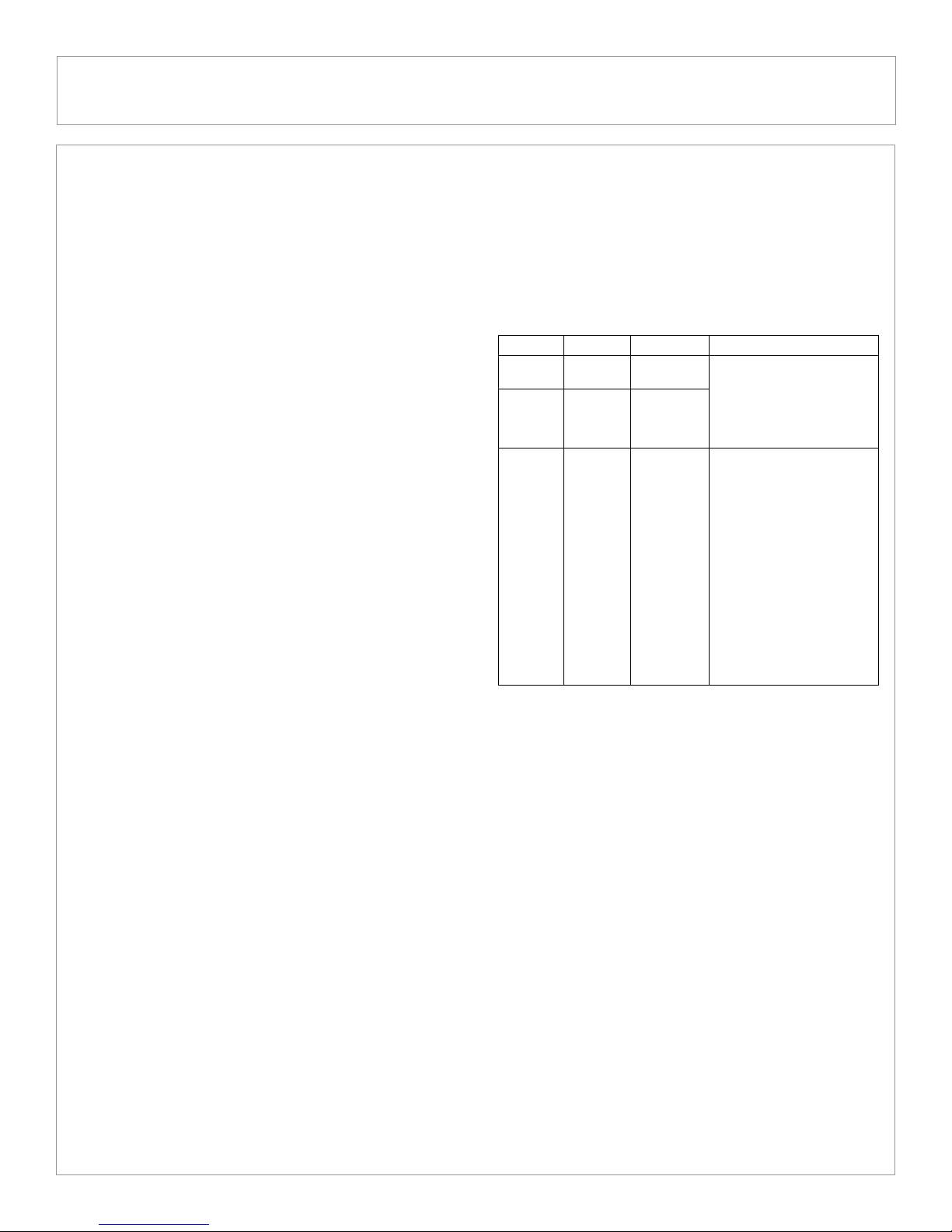
Grounding
• Panel frames should be connected to an earth ground for safety
and protection from lightning.
• The panel frame is provided with grounding holes that
accommodate self-tapping screws. If grounding holes are utilized,
a #10-32 stainless steel thread cutting screw is required.
• The following specic grounding methods utilizing thread cutting
screws have been successfully tested with ES-A panels to the
UL1703 standard. This does not prohibit the use of other methods,
providing that all applicable codes and standards are met.
Device Part No. Material Bonding Method to Frame
ILSCO GBL-4DBT Tin plated • 10-32 cutting screw at
lay-in lug copper grounding hole locations.
Tyco SolKip
Copper alloy
• The use of a nut is required
lay-in lug 1954381-1 plated with behind the screw to create
tin over a positive means of
nickel attachment to the frame.
• 10-32 cutting screw at
grounding hole locations.
Cutting • The use of a nut is required
screw with
behind the screw to create
3 washers N/A Stainless a positive means of
(2 cupped,
steel attachment to the frame.
1 star) •
The grounding wire must be
placed between 2 cupped
washers and around the
10-32 cutting screw.
• A star washer is required
between the panel
frame and the cupped
washer to ensure that the
frame anodized layer is
penetrated.
• Evergreen panels can also be grounded using third party
grounding washers or clip devices provided the devices are
listed and identied for grounding the metallic frames of PV
panels and the devices are installed in accordance with the
manufacturer’s specied instructions.
Mechanical Installation
• Panels should be mounted to maximize direct exposure to sunlight
and to eliminate or minimize shadowing.
• Even partial shadowing can substantially reduce panel and system
output.
• Panels must be securely fastened using support frames or
mounting kits specialized for PV applications.
• Panels may be mounted at any angle from vertical to horizontal
orientation.
• Care must be taken to avoid low tilt angles which may cause dirt to
build-up on the glass against the frame edge.
• Dirt build-up on the surface of the panel can cause active solar
cells to be shaded and electrical performance to be impaired.
• Contact Evergreen Solar for more information regarding minimum
recommended tilt angles for specic panel products.
• For roof mounted systems, provide adequate rear ventilation
under a panel for cooling (100mm: 4 in. gap minimum).
• Clearance of 7mm:¼ in or more between panels is required to
allow for thermal expansion of the frames.
• Always keep the back surface of the panel free from any foreign
objects or structural elements which could come into contact with
the panel, especially when the panel is under mechanical load.
2 of 4 Valid from 1st June 2009 / IM-ES-A_fa3_US_010609_ETL © 2009 Evergreen Solar, Inc.
ES-A Series Photovoltaic Panels - Black Frames
Safety, Installation and Operation Manual

• Ensure panels are not subjected to wind or snow loads in excess of
the maximum permissible loads and are not subjected to excessive
forces due to thermal expansion of the support structure.
• Evergreen Solar permits several different mounting methods. The
permissible mounting methods and maximum permissible wind
and snow loads are detailed in the Mounting Guide available from
Evergreen Solar (ETL listed version).
• For permission to use mounting methods not described in the
Mounting Guide (ETL listed version), please consult Evergreen
Solar. Failure to do so will void the warranty and panel
certication.
• Always follow the mounting equipment vendors’ installation
instructions in addition to the instructions found in the Mounting
Guide (ETL listed version). In cases where the vendors’ instructions
are more stringent than those detailed in the Mounting Guide
(ETL listed version), the vendors’ instructions shall apply.
• In cases where the maximum permissible loading determined
by the mounting equipment vendor is less than the maximum
permissible load stated in the Mounting Guide (ETL listed
version), the maximum loads determined by the vendor should
always be used.
• The maximum permissible loads apply to uniformly distributed
wind or snow loading. Care should be taken to avoid mounting
panels in areas that are prone to drifting snow, icicle and/or ice
dam formation.
Operation and Maintenance
• No routine maintenance is required. However it is advisable to
perform periodic inspection of the panels for damage to glass,
back-skin, frame, junction box or external electrical connections.
• Check electrical connections for loose connections and
corrosion.
• PV panels can operate effectively without ever being washed,
although removal of dirt from the front glass can increase
output.
• Evergreen Solar panels use front glass with a wear resistant and
durable anti-reection coating designed to improve electrical
performance.
• Water can be used for regular washing or rinsing of the coated
front glass to remove dust, dirt or other deposits.
• To remove ingrained dirt, the coated glass can be washed with a
micro-ber cloth and ethanol or a conventional glass cleanser.
• No aggressive and abrasive cleansers or chemicals should ever be
used on the coated front glass. No alkali based chemicals should
be used, including ammonia based solutions.
• Always wear rubber gloves for electrical insulation whilst
maintaining, washing or cleaning panels.
• Panel frames are made of architectural grade, black hard-
coat anodized aluminum which provides excellent protective
properties and color stability.
• Deposits of foreign material on the frame surface can be cleaned
using a wet sponge or cloth and dried in air or by using a clean
chamois.
• Alternatively, a mild detergent or glass cleaner may be used.
Never use aggressive alkaline or acid cleaners to clean any part
of the panel.
• Foreign material on the frame may in some instances look like
small scratches, but in most cases can be removed by cleaning.
Underwriters Laboratories and Canadian
Standard ULC/ORD-C1703-01 Information
• Under normal conditions, a photovoltaic panel is likely to
experience conditions that produce more current and/or voltage
than reported at Standard Test Conditions. Accordingly, the
values of Isc and Voc marked on this panel should be multiplied
by a factor of 1.25 when determining component voltage ratings,
conductor capacities, fuse sizes, and size of controls connected
to the PV output.
• Refer to section 690-8 of the National Electric Code (NEC) for an
additional multiplying factor of 125% (80% de-rating) which may
be applicable.
• Conductor recommendations: single conductor cable, type USE-
2 (non-conduit) or PV wire. 10AWG (6mm2 minimum).
• For compliance with Canadian Standard ULC/ORD-C1703-1,
the installation shall be in accordance with CSA-C22.1, Safety
Standard for Electrical Installations, Canadian Electrical Code,
Part 1.
Disclaimer of Liability
Since the use of this Safety, Installation and Operation Manual and the
conditions or methods of installation, operation, use and maintenance
of the panel are beyond Evergreen Solar control, Evergreen Solar does
not assume responsibility and expressly disclaims liability for loss,
damage, injury or expense arising out of or in any connected with such
installation, operation, use or maintenance of the panel.
Evergreen Solar assumes no responsibility for any infringement of
patents or other rights of third parties that may result from use of the
panel. No license is granted by implication or otherwise under any
patent or patent rights.
The information in this Manual is based on Evergreen Solar knowledge
and experience and is believed to be reliable; but such information
including product specications (without limitations) and suggestions
do not constitute a warranty, expressed or implied. Evergreen Solar
reserves the right to make changes to the product, specications or
this Manual without prior notice.
Note: This document may be provided in multiple languages. If there is
a conict among versions, the English language version dominates.
3 of 4 Valid from 1st June 2009 / IM-ES-A_fa3_US_010609_ETL © 2009 Evergreen Solar, Inc.
ES-A Series Photovoltaic Panels - Black Frames
Safety, Installation and Operation Manual
4 of 4
www.evergreensolar.com
Valid from 1st June 2009 / IM-ES-A_fa3_US_010609_ETL © 2009 Evergreen Solar, Inc.
ES-A Series Photovoltaic Panels - Black Frames
Safety, Installation and Operation Manual
Temperature Coefficients
gPmp -0.43 (%/°C)
b Vmp -0.40 (%/°C)
a Imp -0.03 (%/°C)
b Voc -0.31 (%/°C)
a Isc +0.05 (%/°C)
Number of Cells 114
Bypass Diodes
2x Type Schottky
UCQS30A04, 45 V, 30 A
Max. Series Fuse/
Max. Reverse Current
20A
UL Rated
System Voltage 600V DC Maximum
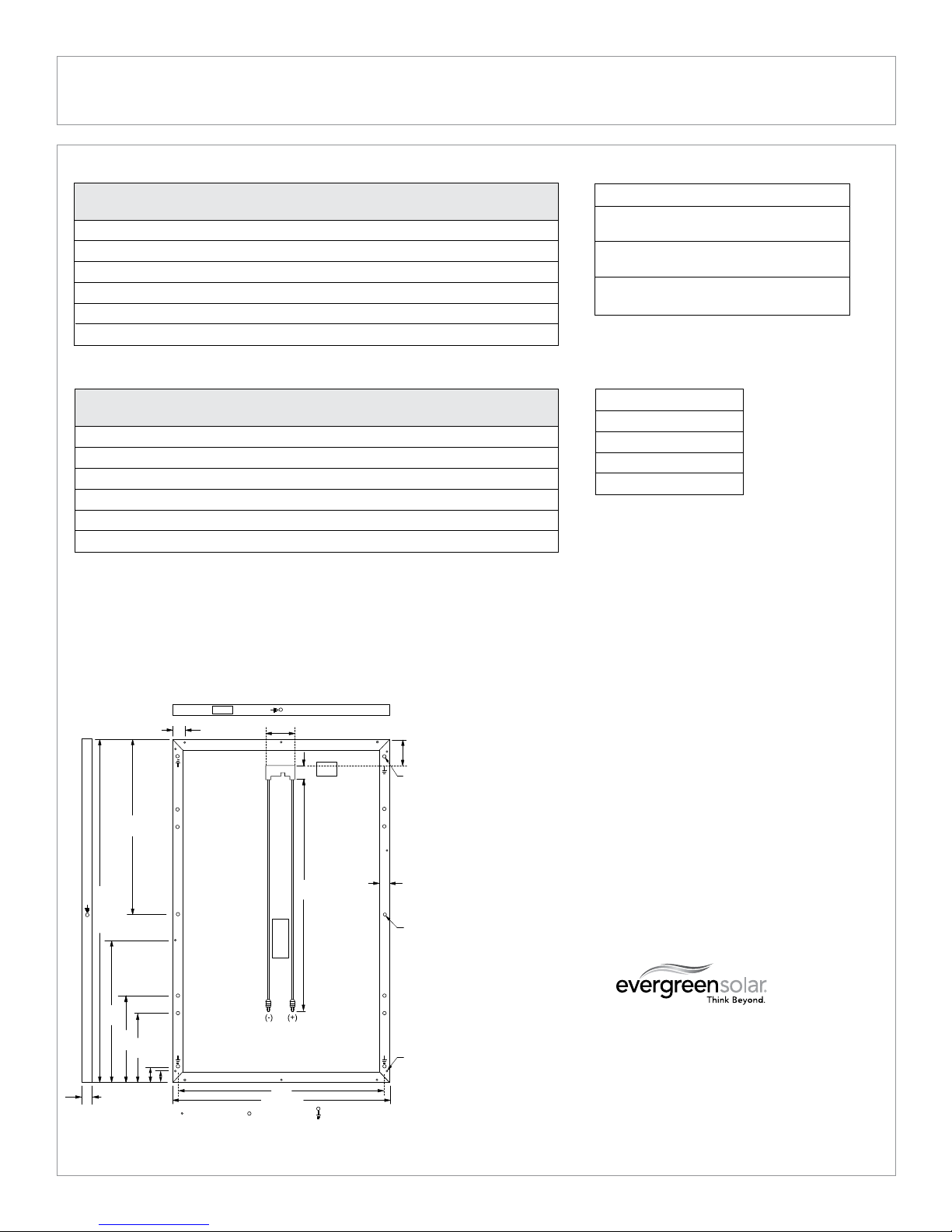
Mechanical Specifications
ES-A-190, 195, 200, 205, 210
ALL DIMENSIONS IN INCHES; WEIGHT 41 LBS. (18.6 KG)
Worldwide Headquarters
Evergreen Solar Inc.
138 Bartlett Street
Marlboro, MA 01752 USA
T: +1 508.357.2221
F: +1 508.229.0747
info@evergreensolar.com
Customer Service -
Americas and Asia
Evergreen Solar Inc.
138 Bartlett Street
Marlboro, MA 01752 USA
T: +1 508.357.2221
F: +1 508.229.0747
sales@evergreensolar.com
PANEL
SERIAL NUMBER
JUNCTION BOX
(IP65)
12x FRAME
DRAINAGE HOLES
(NOT TO BE USED
FOR MOUNTING)
PANEL
ID LABEL
DRAINAGE HOLES MOUNTING HOLES GROUNDING HOLES
4.9
10x ø.26
MOUNTING
HOLES
FOR ¼" BOLT
CABLES
(10 AWG, UL4703,
PV-WIRE)
PANEL
ID LABEL
MC® LOCKABLE
CONNECTORS
(TYPE 4;
LOCKING SLEEVE
NOT PROVIDED)
8x ø.16
GROUNDING
HOLES
2.2
2.3
42.1
32.5
3.1
BLACK ANODIZED
ALUMINUM FRAME
35.9
37.5 (+/-0.1)
1.8 (+0.02/-0)
2.2
2.8 13.0
16.2
26.7
65.0 (+/-0.1)
1.6
* At Standard Test Conditions: 1000W/m2, 25°C cell temperature, AM 1.5 spectrum. Minimum specied power rating is 0% below Pmp
for all products; other specications are +/-10% of measured values per ASTM E 892. Specications subject to change without notice.
Warranty details available on request.
** At PTC (PV-USA Test Conditions): 1000 W/m2, 20°C ambient temperature, 1 m/s wind speed.
*** At Nominal Operating Cell Temperature Conditions: 800W/m2, 20°C ambient temperature, wind velocity 1m/s, AM 1.5 spectrum.
The relative rediction of panel efciency at 200 W/m2 irradience in relation to 1000 W/m2 both at 25°C cell temperature and spectrum AM 1.5 is 0%.
Electrical Specifications at STC*
ES-A-190 ES-A-195 ES-A-200 ES-A-205 ES-A-210
-fa3 -fa3 -fa3 -fa3 -fa3
Pmp (W) 190 195 200 205 210
Pptc** (W) 171.3 175.9 180.6 185.2 189.8
Vmp (V) 17.7 17.9 18.1 18.2 18.3
Imp (A) 10.74 10.90 11.05 11.27 11.48
Voc (V) 22.4 22.5 22.6 22.7 22.8
Isc (A) 11.65 11.70 11.80 11.93 12.11
Electrical Specifications at NOCT***
ES-A-190 ES-A-195 ES-A-200 ES-A-205 ES-A-210
-fa3 -fa3 -fa3 -fa3 -fa3
Pmp (W) 139.2 142.7 146.4 150.1 153.8
Vmp (V) 16.3 16.4 16.5 16.6 16.7
Imp (A) 8.54 8.70 8.87 9.04 9.21
Voc (V) 20.4 20.6 20.8 21.0 21.1
Isc (A) 9.26 9.32 9.44 9.57 9.76
TNOCT (°C) 45.4 45.4 45.4 45.4 45.4
This manual suits for next models
4
Other evergreensolar Solar Panel manuals

evergreensolar
evergreensolar ES-A Series Setup guide

evergreensolar
evergreensolar ES-C-70-fa5 Setup guide

evergreensolar
evergreensolar ES-A Series Setup guide

evergreensolar
evergreensolar ES-A Series Setup guide

evergreensolar
evergreensolar ES-A Series Installation instructions manual

evergreensolar
evergreensolar ES Series Setup guide

evergreensolar
evergreensolar SPRUCE LINE ES-170-RL User manual

evergreensolar
evergreensolar Cedar Line User manual

evergreensolar
evergreensolar ES-C-70-fa5 Setup guide


