shelolab SRI21D User manual

DIURNAL PLANT GROWTH CHAMBER
115 Voltage
Installation - Operation Manual
SRI21D

2 | Page
Not for Fly Cultivation
This unit is not designed to hold fruit flies (Drosophila melanogaster). Use with flies voids the
manufacturing warranty and risks damaging the unit.
Other incubator models in the SRI family are manufactured specifically for fly applications. Talk to
your distributor or customer service representative to identify a model compatible with your study or
production model.

3 | Page
SRI21D DIURNAL PLANT GROWTH CHAMBER
115 Voltage
Installation and Operation Manual
Part Number (Manual): 4861744
Revision: February 12, 2018
These units are compliant with the following standards for use within an ambient air pressure range
of 22.14 – 31.3 inHg (75 – 106 kPa), with no flammable, volatile, or combustible materials being
heated.
CAN/CSA C22.2 No. 61010-1:2012
CAN/CSA C22.2 No. 61010-2-010:2004 Reaffirmed: 2014-07
UL 61010-1:2012-05
UL 61010A-2-010:2002-03
EN 61010-1:2010
EN 61010-2-010:2014
Supplemented by: UL 61010-2-010:2015

4 | Page
TABLE OF CONTENTS
INTRODUCTION ........................................................................................................................................................ 5
Read this Manual....................................................................................................................................................................5
Safety Considerations and Requirements ......................................................................................................................5
Contacting Assistance ..........................................................................................................................................................6
Engineering Improvements..................................................................................................................................................6
Temperature Reference Sensor Device .......................................................................................................................... 7
RECEIVING YOUR UNIT ........................................................................................................................................... 9
Inspect the Shipment.............................................................................................................................................................9
Orientation Photo ................................................................................................................................................................. 10
Recording Data Plate Information.................................................................................................................................... 11
INSTALLATION .........................................................................................................................................................13
Installation Checklist ........................................................................................................................................................... 13
Required Ambient Conditions........................................................................................................................................... 14
Environmental Disruption Sources .................................................................................................................................. 14
Power Source Requirements ............................................................................................................................................ 15
Lifting and Handling ............................................................................................................................................................ 15
Install the Chamber in Location ....................................................................................................................................... 16
Leveling................................................................................................................................................................................... 16
Attach the Chamber Door Handle .................................................................................................................................. 16
Adjust Shelves........................................................................................................................................................................17
Deionized and Distilled Water.......................................................................................................................................... 18
Installation Cleaning and Disinfection ........................................................................................................................... 18
GRAPHIC SYMBOLS ................................................................................................................................................19
CONTROL PANEL OVERVIEW ...............................................................................................................................21
OPERATION.............................................................................................................................................................. 23
Theory of Operation ........................................................................................................................................................... 23
Put the Chamber into Operation..................................................................................................................................... 25
Set the Manual Day Mode Temperature Set Point ................................................................................................... 26
Set the Manual Night Mode Temperature Set Point................................................................................................. 29
Program Clock Times and Cycle Temperature Set Points...................................................................................... 32
Load the Chamber .............................................................................................................................................................. 38
Condensation and the Dew Point .................................................................................................................................. 38
Launching the Day - Night Cycle .................................................................................................................................... 39
Accessory Compatibility and Power Outlet ................................................................................................................. 39
Set the Over Temperature Limit...................................................................................................................................... 40
USER MAINTENANCE..............................................................................................................................................41
Cleaning and Disinfecting.................................................................................................................................................. 41
Minimizing Contamination Exposure ............................................................................................................................. 42
Electrical Components....................................................................................................................................................... 42
Refrigeration and Defrosting............................................................................................................................................ 43
Diagnostics - Temperature Issues.................................................................................................................................. 59
UNIT SPECIFICATIONS .......................................................................................................................................... 67
Weight......................................................................................................................................................................................67
Dimensions.............................................................................................................................................................................67
Capacity ..................................................................................................................................................................................67
Max Shelves For Unit ......................................................................................................................................................... 68
Shelf Capacity by Weight.................................................................................................................................................. 68
Temperature ......................................................................................................................................................................... 68
Power...................................................................................................................................................................................... 68
PARTS AND CONSUMABLES................................................................................................................................ 69

5 | Page
INTRODUCTION
Thank you for purchasing a SHEL LAB unit. We know you have many choices in today’s competitive
marketplace when it comes to constant temperature equipment. We appreciate you choosing ours. We
stand behind our products and will be here for you if you need us.
READ THIS MANUAL
Failure to follow the guidelines and instructions in this user manual may create a protection
impairment by disabling or interfering with the unit safety features. This can result in injury or death.
Before using the unit, read the manual in its entirety to understand how to install, operate, and
maintain the unit in a safe manner. Keep this manual available for use by all operators. Ensure all
operators are given appropriate training before the unit begins service.
SAFETY CONSIDERATIONS AND REQUIREMENTS
Follow basic safety precautions, including all national laws, regulations, and local ordinances in your
area regarding the use of this unit. If you have any questions about local requirements, please
contact the appropriate agencies.
SOPs
Because of the range of potential applications, this unit can be used for, the operator or their
supervisors must draw up a site-specific standard operating procedure (SOP) covering each
application and associated safety guidelines. This SOP must be written and available to all operators
in a language they understand.
Intended Applications and Locations
The incubators are intended for constant temperature, non-humidified general incubation
applications in professional, industrial, and educational environments. The units are not intended for
use at hazardous or household locations.
Power
Your unit and its recommended accessories are designed and tested to meet strict safety
requirements.
•The unit is designed to connect to a power source using the specific power cord type
shipped with the unit.
•Always plug the unit power cord into a protective earth grounded electrical outlet
conforming to national and local electrical codes. If the unit is not grounded properly, parts
such as knobs and controls can conduct electricity and cause serious injury.
•Do not bend the power cord excessively, step on it, or place heavy objects on it.
•A damaged cord can be a shock or fire hazard. Never use a power cord if it is damaged or
altered in any way.
•Use only approved accessories. Do not modify system components. Any alterations or
modifications to your unit not explicitly authorized by the manufacturer can be dangerous
and will void your warranty.

6 | Page
INTRODUCTION
CONTACTING ASSISTANCE
Phone hours for Sheldon Technical Support are 6 am – 4:30 pm Pacific Coast Time (west coast of
the United States, UTC -8), Monday – Friday. Please have the following information ready when
calling or emailing Technical Support: the model number and the serial number (see page 11).
EMAIL: [email protected]
PHONE: 1-800-322-4897 extension 4, or (503) 640-3000
FAX: (503) 640-1366
Sheldon Manufacturing, INC.
P.O. Box 627
Cornelius, OR 97113
ENGINEERING IMPROVEMENTS
Sheldon Manufacturing continually improves all of its products. As a result, engineering changes and
improvements are made from time to time. Therefore, some changes, modifications, and
improvements may not be covered in this manual. If your unit’s operating characteristics or
appearance differs from those described in this manual, please contact your SHEL LAB dealer or
customer service representative for assistance.

7 | Page
INTRODUCTION
TEMPERATURE REFERENCE SENSOR DEVICE
Must be purchased separately
A reference sensor device is required for calibrating the incubator temperature display.
Reference devices must meet the following standards:
•Accurate to at least 0.1°C
The device should be regularly calibrated, preferably by a third party.
Temperature Probe
Use a digital device with a wire thermocouple probe that can be introduced into the incubation chamber
through the unit access port. Select a thermocouple suitable for the application temperature you will be
calibrating at.
Why a Probe?
Reference readings taken outside the chamber using wire temperature probes avoid chamber door
openings. Openings disrupt the chamber temperature. Each disruption requires a minimum 1-hour wait
to allow the atmosphere to re-stabilize before continuing.
No Alcohol or Mercury Thermometers
Alcohol thermometers do not have sufficient accuracy to conducti accurate temperature calibrations.
Never place a mercury thermometer in the incubation chamber! Always use thermocouple probes.
Temperature Reference

8 | Page
INTRODUCTION

9 | Page
RECEIVING YOUR UNIT
INSPECT THE SHIPMENT
•When a unit leaves the factory, safe delivery becomes the responsibility of the carrier.
•Damage sustained during transit is not covered by the manufacturing defect warranty.
When you receive your unit, inspect it for concealed loss or damage to its interior and exterior. If you
find any damage to the unit, follow the carrier’s procedure for claiming damage or loss.
1. Carefully inspect the shipping carton for damage.
2. Report any damage to the carrier service that delivered the unit.
3. If the carton is not damaged, open the carton and remove the contents.
4. The unit should come with an Installation and Operation Manual.
5. Verify that the correct number of accessories has been included.
o4 shelves
o1 chamber door key
o1 Chamber door handle with installation instructions
10 | Page
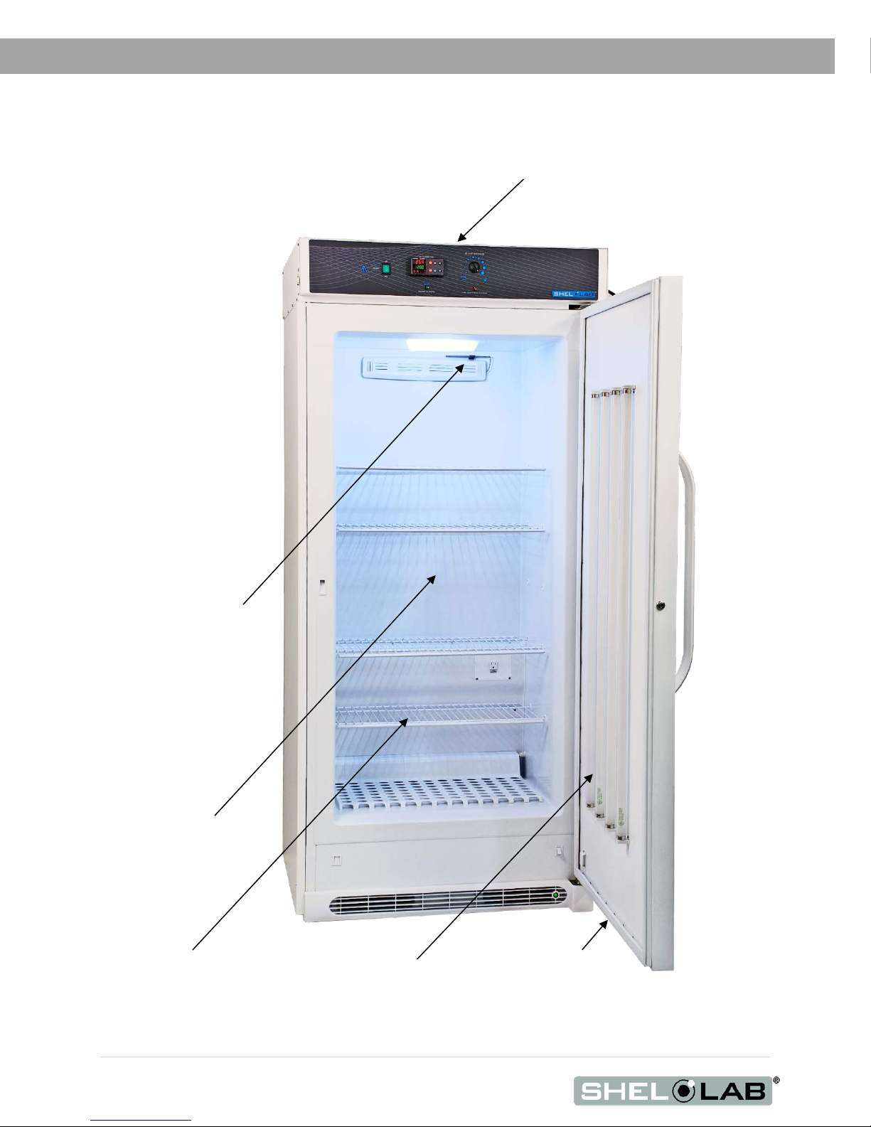
Figure
1: SRI21D
RECEIVING YOUR UNIT
ORIENTATION PHOTO
Control Panel
Temperature Probe
Wire Shelf,
1 of 4
Chamber Door
Cultivation
Chamber
Door Gasket
Day Period
Fluorescent
Illumination Blubs

11 | Page
RECEIVING YOUR UNIT
RECORDING DATA PLATE INFORMATION
The unit data plate contains the chamber model number and serial number. Record this information
below for future reference.
•The data plate is located on the unit exterior, on the top, right side.
Model Number
Serial Number

12 | Page
RECEIVING YOUR UNIT

13 | Page
INSTALLATION
INSTALLATION CHECKLIST
For installing the unit in a new workspace.
Pre-Installation
Check that the required ambient conditions, ventilation, and spacing for
the chamber are met, page 14.
•Unit dimensions may be found on page 67
Check for performance-disrupting heat and cold sources in the environment,
page 14
Check that a suitable electrical outlet and power supply is present, page 15
Install the Chamber in a suitable workspace location
Review the lifting and handling instructions, page 15
Install the chamber in its workspace location, page 15
Make sure the chamber is level, page 16
Set up the Chamber for use
Install the chamber door handle, page 16
Verify that all packaging has been removed from the chamber shelving and
incubation chamber, page 17
Clean the cultivation chamber if needed, page 18

14 | Page
INSTALLATION
REQUIRED AMBIENT CONDITIONS
The SRI chambers are intended for use indoors at room temperatures between 15°C and 30°C
(59°F and 86°F), at no greater than an ambient 80% Relative Humidity (at 25°C / 77°F). Allow a
minimum of 4 inches (100 mm) between the unit and walls or partitions, and 2.5 inches (60 mm) of
clearance above the top of the chamber for unobstructed airflow.
Operating the unit outside these conditions may adversely affect its temperature range and stability.
ENVIRONMENTAL DISRUPTION SOURCES
When selecting a location to install the chamber, consider all environmental conditions that can
affect the unit temperature performance. For example:
•Proximity to ovens, autoclaves, and any device that produces significant radiant heat
•Heating and cooling ducts, or other sources of fast-moving air currents
•High-traffic areas
•Direct sunlight
2.5” (60 mm)
4” (100 mm)
4” (100 mm)
4” (100 mm) between the
back of the incubator and
any wall or other partition.
Leave sufficient room in
front of the unit for the
door to swing freely.

15 | Page
INSTALLATION
POWER SOURCE REQUIREMENTS
When selecting a location for the unit, verify that each of the following requirements is satisfied.
Power Source: The power source must match the voltage and ampere requirements listed on the
unit data plate. These units are intended for 115 VAC 50/60 Hz applications at 9 amps.
•Supplied voltage must not vary more than 10% from the data plate rating. Damage to the
unit may result if supplied voltage varies more than 10%.
•Wall power sources must be protective earth grounded.
•Use a separate circuit to prevent loss of product due to overloading or circuit failure.
•The wall power sources must conform to all national and local electrical codes.
Power Cord: The unit must be positioned so that all end-users can quickly unplug the power cord in
the event of an emergency.
•The unit is provided with an integral 125V, 15 Amp, NEMA 5-15P, 8ft (2.5m) power cord.
Circuit Breaker: The unit is provided with an integral circuit breaker to protect against overcurrent
conditions.
•Always determine the cause of an overcurrent event before resetting a tripped circuit
breaker.
LIFTING AND HANDLING
The unit should only be lifted by its bottom surfaces using proper heavy lifting machinery such as a
forklift or pallet jack.
•Handles and knobs are inadequate for lifting or stabilization.
•The unit should be completely restrained from tipping during lifting.
•Transporting the unit while lifted is not recommended and may be hazardous.
•Secure the door in the closed position prior to lifting the unit.
•Do not attempt to move the unit while in operation or before the unit has cooled.

16 | Page
INSTALLATION
INSTALL THE CHAMBER IN LOCATION
Install the unit in a workspace location that meets the criteria discussed in the previous entries of the
Installation section.
LEVELING
The unit must be level and stable for safe operation. Ensure that the chamber is placed on a flat and
level surface, prior to placing the unit in operation.
ATTACH THE CHAMBER DOOR HANDLE
Attach provided the door handle to the chamber door.
•Use the instructions packaged with the handle.
17 | Page
INSTALLATION
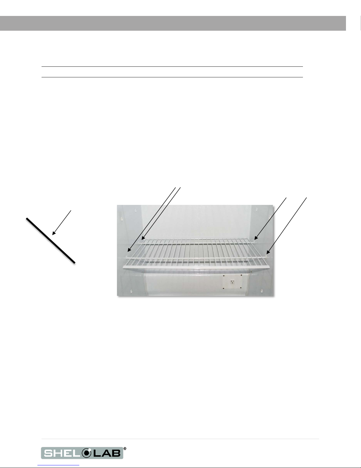
ADJUST SHELVES
Note: The form factor of the shelves may vary slightly by year of production.
The unit ships with its shelves installed in the incubation chamber. Tape, foam, and other packing
dunnage is used to secure the shelves during transit and prevent damage to the chamber interior.
1. Remove all shipping dunnage from the shelving.
Optional: Shelf Adjustment
Move the shelves as needed for your application.
Figure 2: Shelf Installed
2. Install the right side
mounting prongs first
3. Install the left side
mounting prongs last
1. Tilt the shelf at rough 60°
when moving up or down
to avoid scarping the
chamber walls.

18 | Page
INSTALLATION
DEIONIZED AND DISTILLED WATER
Do not use deionized water to clean the chamber. Use of deionized water may corrode metal
surfaces and voids the warranty. Sheldon Manufacturing recommends the use of distilled water in
the resistance range of 50K Ohm/cm to 1M Ohm/cm, or a conductivity range of 20.0 uS/cm to 1.0
uS/cm, for cleaning applications.
INSTALLATION CLEANING AND DISINFECTION
If required by your laboratory protocol, clean and disinfect the cultivation chamber and shelving
components prior to installation. Cleaning and disinfecting reduce the risk of contamination. The chamber
and shelving were cleaned and disinfected at the factory, however, Sheldon Manufacturing cannot
guarantee that the chamber was not exposed to contaminants during shipping.
Remove all protective wrappings from shelving components prior to cleaning.
Please see the Cleaning and Disinfection procedure on page 41 of the User Maintenance section
for information on how to clean and disinfect without damaging the chamber and its components.

19 | Page
GRAPHIC SYMBOLS
The unit is provided with graphic symbols on its interior and exterior surfaces. These symbols
identify hazards, as well as the functions of the adjustable components, and important notes in the
user manual.
Symbol Definition
Consult the user manual.
Consulter le manuel d'utilisation
Temperature Display
Indique l'affichage de la température
Over Temperature Limit system
Indique le système de dépassement de temperature
AC Power
Repère le courant alternatif
Indicates I/ON and O/OFF
I indique que l'interrupteur est en position marche.
O indique que le commutateur est en position d'arrêt.
Indicates protective earth ground
Repère terre électrique
Adjusts UP and DOWN
Ajuster le haut et vers le bas
Potential Shock Hazard
Signale danger électrique
Recycle the unit. Do not dispose of in a landfill.
Indique que l'unité doit être recyclée. Ne pas jeter dans une
décharge)

20 | Page
GRAPHIC SYMBOLS
Table of contents
Other shelolab Accessories manuals


