Shenyang 245 Factory C9350C User manual
1
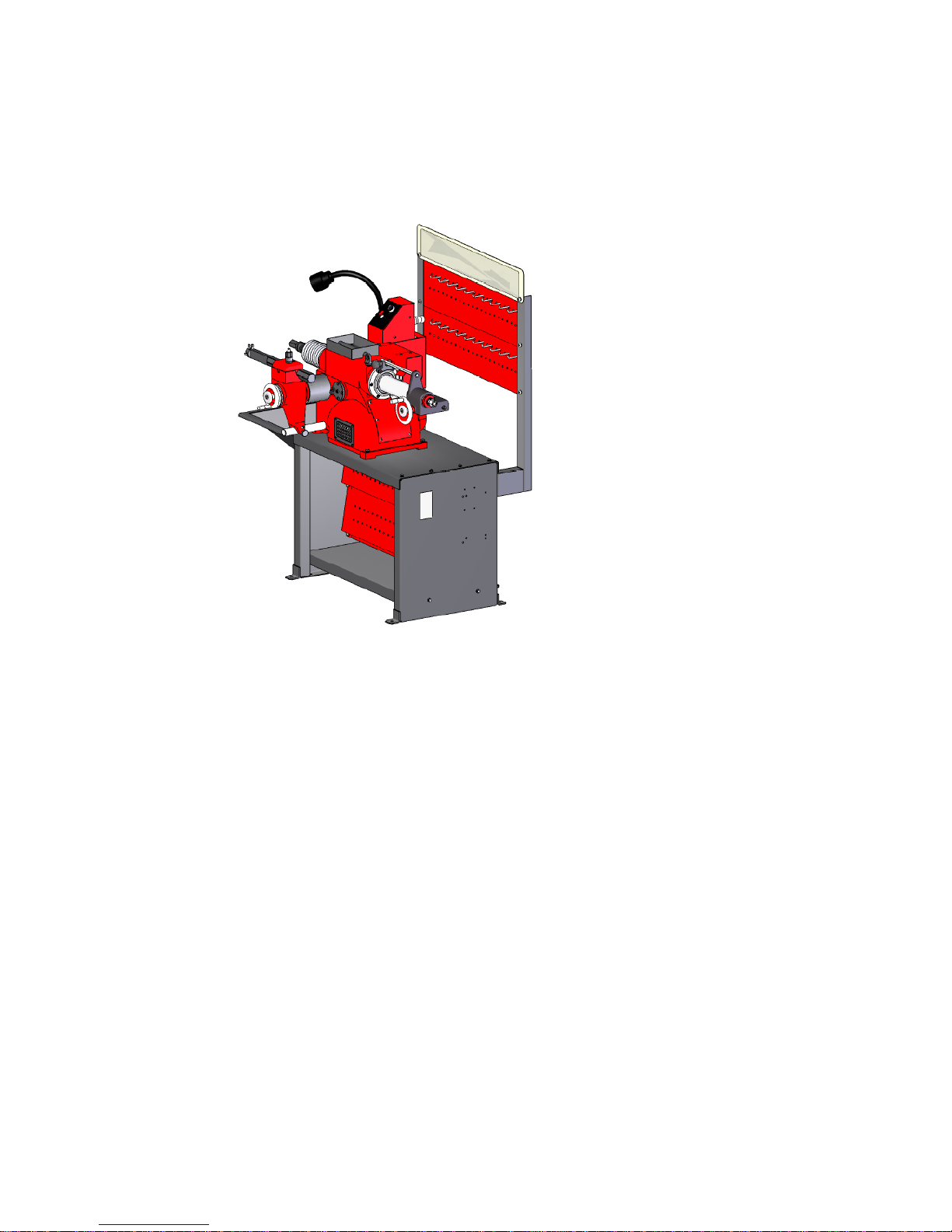
C9350C/C9370C Drum&Disc Brake Lathes
Handbook
Installation Instructions
Operating Instructions
Safety Instructions
Maintenance Instructions
READ these instructions before placing unit in service.KEEP these and other
materials delivered with the unit in a binder near the machine for ease of
reference by supervisors and operators.
SHENYANG 245 FACTORY

2
Table of Contents
Definitions of Hazard Levels……………………………………………3
User’s Responsibility……………………………………………………4
Safety Notices and Decals………………………………………………5
Warning………………………………………………………………………5
Cautions and Dangers……………………………………………………6
Important Safety Instructions……………………………………………6
Before You Begin
Receiving……………………………………………………………………8
Electrical Requirements……………………………………………………9
Installation …………………………………………………………………9
Operating Specifications …………………………………………………11
Principle Operating parts…………………………………………………12
Arbor Installation……………………………………………………………12
Chang and Choose Arbor…………………………………………………13
Adapters……………………………………………………………………13
Basic operation
Spindle………………………………………………………………………14
Control and Operating………………………………………………………14
Spindle Speed………………………………………………………………14
Spindle Speed Adjustment…………………………………………………14
Cross Feed……………………………………………………………………15
V-belt Tension and Adjustments……………………………………………15
Basic Operation of Handwheels……………………………………………16

3
Reconditioning Brake Drums
Preparation…………………………………………………………………16
Mounting Drums……………………………………………………………17
Reconditioning Disc Brake Rotors
Preparation…………………………………………………………………20
Twin Cutters…………………………………………………………………21
Rotor Mounting………………………………………………………………21
Set Up and Reconditioning Rotors…………………………………………22
Typical Adapter Usage for Rotors…………………………………………25
Adapter Usage for Drums……………………………………………………25
Cross Feed Extension Installation Instructions…………………………25
Maintenance and Service
Oiling……………………………………………………………………………26
Cleaning………………………………………………………………………27
Care of Arbors and Adapters………………………………………………27
Important Information Regarding Operation Safety and Eye and Face
Protection………………………………………………………………………28
Definitions of Hazard Levels
Identify the hazard levels used in this manual with the following definitions and
signal words:
DANGER Watch for this symbol:
△
!DANGER
It Means: Immediate hazards, which will result in severe personal injury or
death.

4
WARNING Watch for this symbol:
△
!WARNING
It Means: Hazards or unsafe practices, which could result in severe personal
Injury or death.
CAUTION Watch for this symbol:
△
!CAUTION
It Means: Hazards or unsafe practices, which may result in minor personal
injury or product or property damage.
△
!Watch for this symbol! It means BE ALERT! Your safety, or the safety of
others, is involved!
User’s Responsibility
To maintain machine and user safety, the responsibility of the user is to read
and follow these instructions:
1 Follow all installation instructions and make sure installation conforms to all
applicable Local, Country’s Law, Regulations and Electrical Codes.
2 Carefully check the unit for correct initial function.
3 Read and follow the safety instructions. Keep them readily available for
machine operators.
4 Make certain all operators are properly trained, know how to safety and
correctly operate the unit, and are properly supervised.
5 Allow unit to be operated only with all parts in place and operating safely.
6 Carefully inspect the unit on a regular basis and perform all maintenance as
required.
7 Service and maintain the unit only with authorized or approved replacement
parts.
8 Keep all instructions permanently with the unit and all decals / labels /
notices on the unit clean and visible.

5
9 If ownership of the unit is transferred, provide new user all information,
manuals.
Safety Notices and Decals
For your safety, and the safety of others, read and understand all of the
safety notices and decals included here and on the unit
Read entire manual before installing, operating, or
servicing this equipment.
Proper maintenance and inspection is necessary for
safe operation.
Do not operate a damaged lathe.
Warning
This equipment incorporates parts such as snap switches and power
receptacles which tend to produce arcs or sparks. Therefore, when located in

6
a service facility , the unit should be in a room or enclosure provided for the
purpose, or should be at least 18 " or more above floor to minimize the risk of
igniting fuel vapors.
Cautions and Dangers
1 Eye and face protection requirements:
“Protective eye and face equipment is required to be used.
Protective goggles, safety glasses, or a face shield must be provided by the
purchaser / user and worn by the operator of the equipment. Make sure all eye
and face safety precautions are followed by the operator(s). Keep bystanders
out of the area.
2 Do not remove any safety equipment, belt guards, or shortcut controls or
operations.
3 Make sure drums and rotors are properly and squarely mounted before
starting lathe, and that all parts are secure.
4 Do not wear loose clothing, jewelry, or gloves when operating or working
around a lathe.
5 Do not overload the lathe. Read and understand the lathe specifications.
Overloading is poor machine tool practice, shortens the life of the lathe, and
could cause a failure resulting in personal injury.
Failure to follow danger, warning, and caution instructions may lead to serious
personal injury or death to operator or bystander or damage to property. Do
not operate this machine until you read and understand all the dangers,
warnings and cautions in this manual.
IMPORTANT SAFETY INSTRUCTIONS
Before operating the lathe, review the warning information on the lathe and the
cautions, warnings and dangers in this manual. Also review the following
general safety instructions Failure to follow safety instructions could result in
personal injury to operator or bystanders and damage to the lathe or personal
property.
READ ALL INSTRUCTIONS

7
When using equipment, basic safety precautions should always be followed,
including the following:
1. Keep guards in place.
2. Remove adjusting keys and wrenches from the tool before turning it on.
Make this a habit.
3. Keep work area clean. Cluttered areas and benches invite accidents.
4. Avoid dangerous operating environments. Do not use equipment in areas
where explosive vapors are present or in damp of wet locations. Do not expose
them to rain. Keep the work area clean and well lighted.
5. Keep children away. All bystanders should be kept completely away from
the work area.
6. Make the workshop kid-proof. Use padlocks and master switches, and
remove starter keys.
7. Don't force a tool. It will do the job better and safer at the rate for which it
was designed.
8. Use the right tool. Don't force a tool or an attachment to do a job for which it
was not designed.
9. Dress properly. Keep loose clothing; gloves, neckties, shop rags or jewelry
may get caught in moving parts. Non-slip footwear is recommended. Wear
protective hair covering to contain long hair.
10. Wear eye protection Safety glasses, goggles, or a face shield will help
protect the operator from injury. Use a face shield and dust mask during dusty
operations.
11. Secure the work properly to the unit for setup and tool bit positioning. Do
not attempt to hold a drum or rotor steady on the arbor with your hands. Both
hands must be free to operate unit.
12. Keep distance at all times when lathe is in operation.
13. Maintain tools with care. Keep tools sharp and clean for best and safest
performance. Follow instructions for lubricating and changing accessories.
14. Remove power from the unit and disconnect tools before servicing and
when changing accessories. Follow lock-out and tag-out procedures as
required.

8
15. Avoid unintentional starting. Make sure the switch is in the OFF (O)
position before plugging the machine in or performing any maintenance or
service work.
16. Use recommended accessories. Consult the manufacturer's catalogs for
recommended accessories. Use of improper accessories may cause risk of
injury to operator or bystanders.
17. Never stand or lean on a lathe. Serious injury could occur if the lathe is
tipped or if the cutting tool is unintentionally contacted.
18. Check damaged parts carefully. Before further use of the lathe, a guard or
other part that is damaged should be carefully checked. Immediately replace
all damaged, missing, or non-functional parts. Check for alignment of moving
parts, binding of moving parts, breakage of parts, mounting, and any other
conditions that may affect operation. Guards and other parts that are damaged
should be properly repaired or replaced before lathe is used again.
19. Always feed the work into a blade or cutter and against the direction of
rotation. Cutters and tool bits are designed to cut from the inside of a drum or
rotor to the outer edge, do not attempt to cut from the outside edge in to the
center.
20. Never leave tools running unattended. Turn the power off. Don’t leave the
tool until it comes to a complete stop.
21. Never use compressed air to blow the tool clean. Chips and dust may be
driven between machined parts and into bearing, causing undue wear. They
may also contact persons in the area causing personal injury.
22. Operate the lathe in the proper environment. The lathe incorporates parts
such as snap switches and power receptacles which tend to produce arcs or
sparks. Therefore, when located in a garage, the unit should be in a room or
enclosure provided for the purpose, or should be at least 18”or more above the
floor to minimize the risk of igniting fuel vapors.
Before You Begin
Receiving
The shipment should be thoroughly inspected as soon as it is received .The
signed bill of lading is acknowledgement by the carrier of receipt in good
condition of shipment covered by our invoice.

9
If any of the goods called for on this bill of lading are shorted or damaged, do
not accept them until the carrier makes a notation on the freight bill of the
shorted or damaged goods. Do this for your own protection.
Notify the carrier at once if any hidden loss or damage is discovered after
receipt and request the carrier to make an inspection. If the carrier will not do
so, prepare a signed statement to the effect that you have notified the carrier
(on a specific date) and that the carrier has failed to comply with your request.
It is difficult to collect for loss or damage after you have given the carrier a
clear receipt.
File your claim with the carrier promptly. Support your claim with copies of
the bill of lading, freight bill, invoice, and photographs, if available.
Although our responsibility ceases upon delivery of the shipment to the
carrier, we will gladly assist in tracing lost shipments. Our willingness to assist
in every possible manner does not make us responsible for collection of claims
or replacement of lost or damaged materials. Shipping damage claims will not
be handled under warranty.
Electrical Requirements
The lathe must be properly grounded to protect the operator from shock.
The lathe is equipped with an approved 3-conductor cord and a 3-prong
grounding type plug to fit the proper grounding-type receptacle. Should an
extension cord be required, use 3-conductor cords with 3-prong grounding
plug and 3-prong grounding receptacle properly rated to handle this electrical
power tool only. Do not modify a cord or plug to match a receptacle; have a
qualified electrician install an appropriate outlet to match the lathe
requirements. Repair or replace any worn or damaged power cords
immediately.
Verify that the lathe plug and grounding-type receptacle match as shown in
Figure 1.
Figure 1-Power Cord Plug and Receptacle Types
Installation
1. Assemble bench according to the instructions provided. Tighten all
fasteners securely.
10
2. After assembly, the bench should be leveled and may be bolted down with
bolts or Screws.
3. Unbolt the lathe from the shipping pallet. Lift the lathe onto the bench.
4. Bolt the lathe to the bench with the hardware provided. Tighten fasteners
securely.
5. Remove any packing materials and protective wrapping from the lathe and
components.
6. Make sure lathe is turned off. Plug lathe into a properly installed and
grounded outlet that matches the lathe plug.
7. Remove the shipping plug, insert the oil dipstick, and check oil level. The
lathe is shipped with the correct amount and type of oil. Add oil as necessary to
reach the correct mark on the dipstick. Use only EP-80-90 gear oil. Oil level
should be checked often.
Figure 2- Check oil level
8. Clear the area and turn lathe on. Check for proper operation (motor and
spindle rotation).
Preparation for Use
1. Inspect all adapters and accessories for burrs, nicks, or other damage.
2. Clean accessories with a vaporizing solvent.
3. Apply a light film of oil to all adapters to protect their machined surfaces from
rust. Refer to the maintenance section for more information.
There is a circuit breaker located on the electrical panel to prevent damage
to the lathe in the event the motor is overloaded. Move the switch to the off
position and correct overloading situation before re-setting circuit breaker.
Serious personnel injury could result if circuit breaker is re-set while lathe is
still on.

11
Operating Specifications
Overall lathe height 59" (1500 mm)
Lathe shipping weight 410 lbs(186 kg)
Floor space requirements-length 48"(1219.20 mm)
Floor space requirements- width 35.5" (901.70 mm)
Spindle to floor (mounted on
optional bench)
38" (965 mm) ---- C9350C
39.37" (1000 mm) ---- C9370C
Electrical requirements Standard: 110 VAC, 60 Hz, single-phase,12A
Optional: 220 VAC, 60 Hz, single-phase, 5.21A
Motor Main motor 1 HP(0.75kW), 60 Hz, 115/230 VAC
Feed motor 36W (DC, magnetism forever)
Spindle travel 6-7/8" (175 mm) ---- C9350C
9.875" (251 mm) ---- C9370C
Spindle speed
Inner Groove 70 RPM
Middle Groove 88 RPM
Outer Groove 118 RPM
Spindle feed speed Infinitely variable 0 – 0.023"/r (0 – 0.6mm/r)
Cross travel 3.74 inch (95mm) – C9350C
5.9 inch (150mm) – C9370C
Cross feed speed Infinitely variable 0 – 0.015"/r (0 – 0.4mm/r)
Maximum brake rotor diameter 7 -- 17" (178 -- 432 mm) – C9350C
7 -- 18" (178 -- 457 mm) – C9370C
Cross Feed Extension lathes increases the
maximum rotor diameter to 22"(559 mm)-- C9370C
Maximum brake rotor thickness 1-7/8" (48 mm) – C9350C
4" (102 mm) – C9370C
Brake drum diameter 6-28" (152 -- 711 mm)
Maximum drum depth 6-7/8" (175 mm) – C9350C
9.875" (251 mm) – C9370C
Maximum load
1" (25.4mm) Arbor 100 lbs. (45.36 kg)

12
Principle Operating Parts
1. Bench 2.Radiate Window 3.Cross Feed Lock Knob 4. Slide Shaft 5.Tool
Holder Housing 6. Nut Assembly 7. Tool Holder Cover 8. Cross Feed Assembly
9. Tool Holder 10. Cutter for Turning Drum 11. Square Head Screw GB85-M8x25 12.
Stud 13. Shield 14. Screw Plug 15. Tool Box 16. Cover 17. Control Box 18. Eye
Bolt 19. Portrait Motor Cover 20. Spindle Assembly 21. Portrait Gear Box 22. Belt
Cover 23. Body 24. Back Cover Board
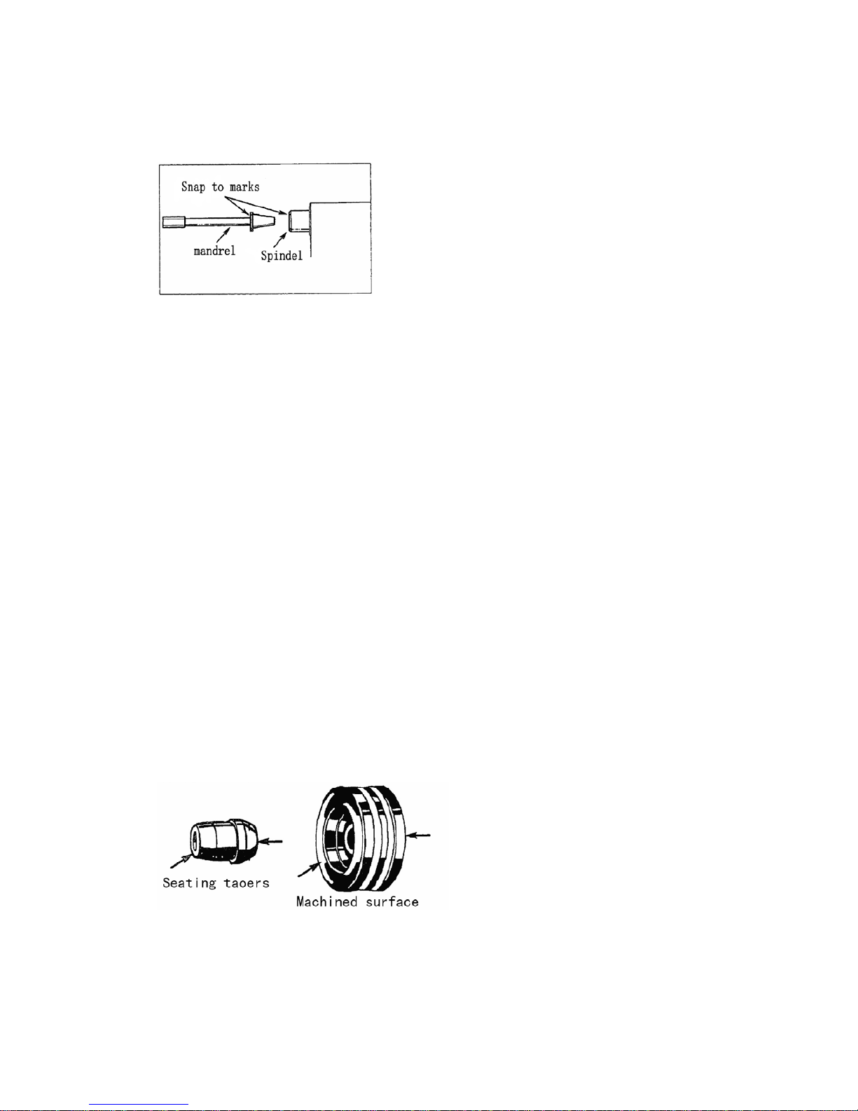
Arbor Installation
The 1”arbor shipped with the lathe has been carefully matched to the lathe
during final assembly and testing. Witness marks have been etched onto the
arbor and the spindle for precise, repeatable alignment.
13
The witness marks must be carefully aligned when installing the arbor
(Figure 3).
1. Locate the witness marks on the arbor and the spindle.
Figure 3-Align witness marks during arbor installation
2. Insert the arbor into the spindle making sure the witness marks are
aligned.
3. Tighten the drawbar (located at the rear of the spindle) to pull the
hardened and ground tapers of the arbor into the matching seats in the
spindle.
Chang and Choose Arbor
New arbor must be marked because of no sign.
1 Spindle hole and arbor tapers must be clear.
2 Fix arbor and lock the drawbar.
3 Measure arbor radial flop with centesimal meter.
4 If radial flop < 0.001 inch, mark a sign on arbor near spindle.
5 If radial flop > 0.001 inch, loose drawbar, round 1/8 arbor and lock drawbar.
6 Check radial flop once more.
7 If radial flop > 0.001 inch, do 5 and 6 until radial flop < 0.001 inch, then mark
a sign.
Adapters
Important: Although the adapters, arbor, and spindle are made of top grade
steel and are turned,hardened,and precision ground to close tolerances,
great care should be taken in their use, handling,and storage. Even the
smallest nick, scratch,or loose chip on the Machined mating surfaces can
cause incorrect rotor mounting alignment. This will cause inaccurate
machining.
Figure 4-Use care to avoid damaging mating surfaces
Always inspect the surface, face, and seating tapers of each part before use.
Wipe each part clean before and after using it. Carefully correct any flaw with a
fine stone. If damage cannot be corrected,replace the part.
14
Basic Operation
To completely understand drum and rotor turning you must have knowledge
of the lathe itself.
Spindle
The spindle is a motor driven shaft that turns the arbor upon which the brake
drum or rotor is mounted. By turning the drum and holding a cutting tool
against the inner braking surface, metal can be removed.
Do not try to move any feed levers or dials without the drive motor running.
Damage may occur to the gear trains.
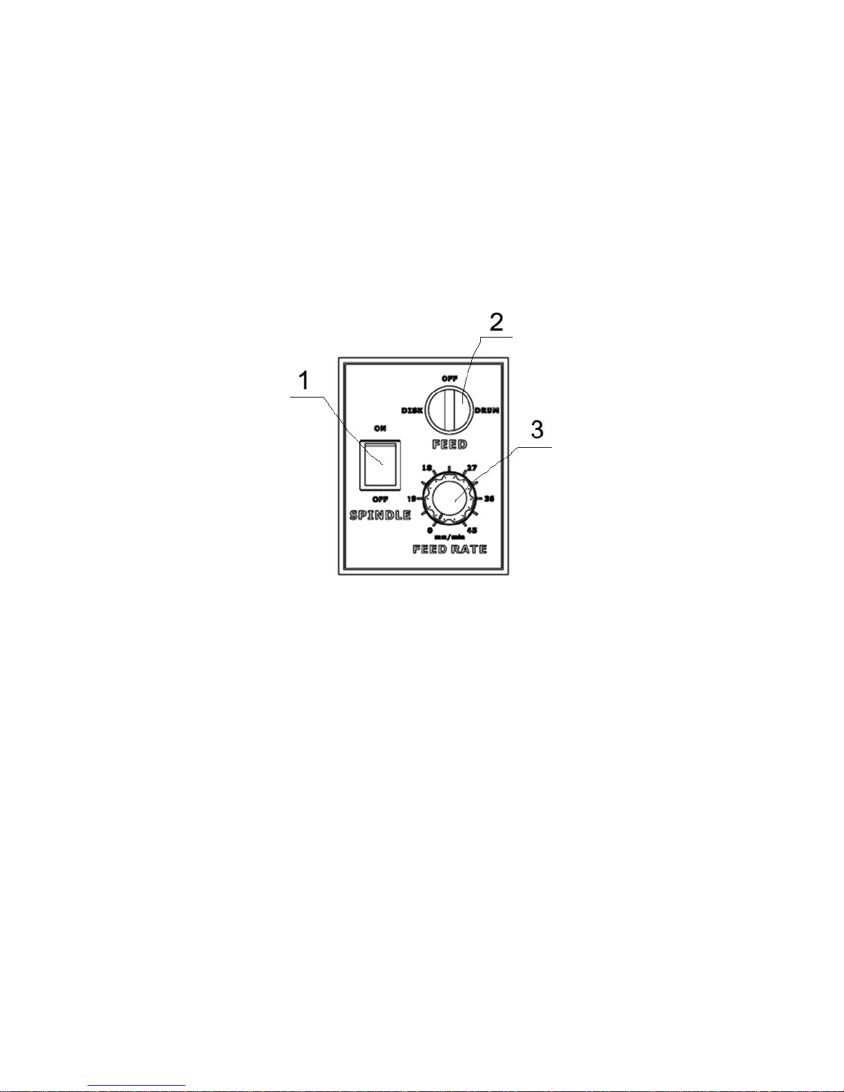
Control and Operating
Fig5 Control Panel
Spindle Motor Switch (Item 1, Figure 5)
The spindle motor switch is a two position toggle switch. When switch OFF, all
power to the spindle motor is shut off. When switched ON, the spindle motor
starts. The spindle will begin to rotate.
Disc/Drum Switch (Item 2, Figure 5)
This switch is a three position select switch. When the left side of this switch is
depressed, power is supplied to the Disc feed motor. When the right side of the
switch is depressed, power is supplied to the Drum feed motor. When the
switch is in the neutral position (centered), power to both motors is OFF.
Feed Timing Potentiometer (Item3, Figure5)
You should turn on the knob clockwise, until you can get an ideal feed speed,
and then, you can refinish the drum or rotor.
Spindle Speed
Spindle speed is adjustable. Refer to the specifications Iisted on page 5 for
the RPM rating of each grove on the V-belt pulley for each model.
Spindle Speed Adjustment
This V-belt adjustment must be made with the lathe off.
15
1. Release the belt tension by moving the V-belt adjusting lever to the right
(clockwise).
2. Move the belt to the pulley groove that will give the correct spindle speed
for the cut to be taken.
3. Reapply tension to the V-belt by moving the adjusting lever back to the
operating position.
Cross Feed
Turn on the disc/drum switch, and located on rotor, tighten the knob on the
cross feed handwheel, turning is starting, until the cutter moved on the rotor
outside. Turn off the disc/drum switch and spindle motor switch.
NOTE: Refer to rotor diameter to find spindle speed and feed speed. Large
diameter, you should select low speed; small diameter, you should select high
speed. “Some experimentation may be required for optimum surface
finish.”
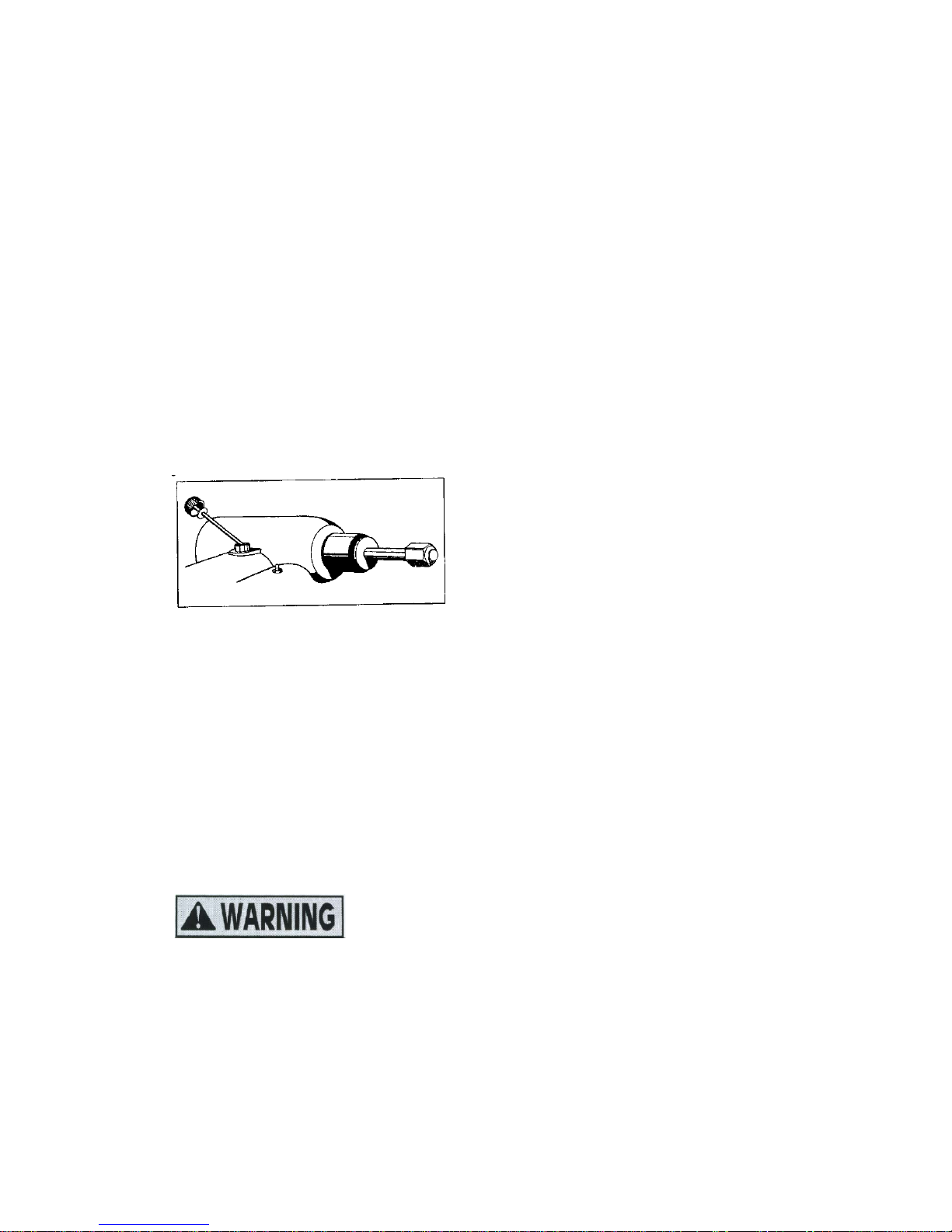
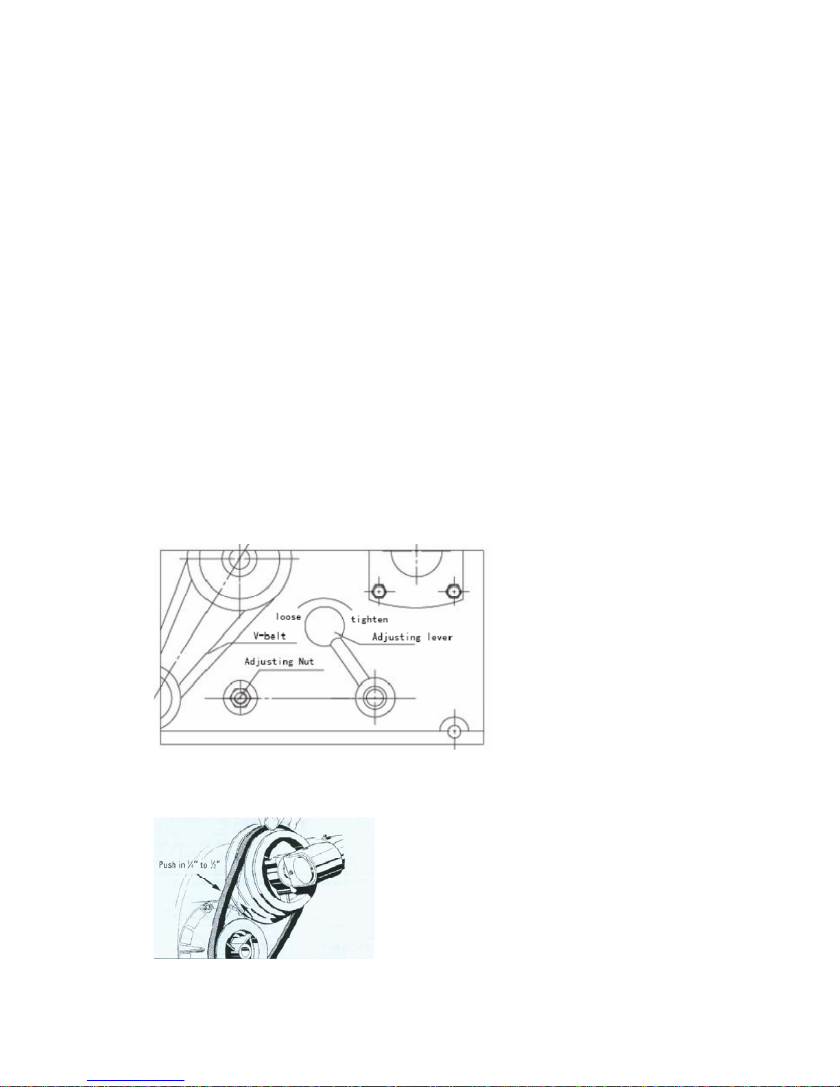
V-Belt Tension and Adjustment
A loose belt can cause slippage when taking heavy cuts.A belt that is too
tight can cause vibration and possible sub-standard finishes on machined
drums and rotors.Check and adjust belt monthly.
There should be between 1/4 to 1/2 of play in the belt.
1. Loosen the adjustment nut.
2. Position the v-belt speed adjusting lever to the right position.
Figure 7- Loosen nut and Engage lever
3. Push in on the belt approximately 1/4 to 1/2 (0.64 to 12.7 mm)and hold.
4. Retighten the adjusting nut.
Figure 8-Press the belt in and tighten adjusting nut

16
Basic Operation of Handwheel
Clockwise rotation of the spindle feed handwheel retracts the spindle in
towards the lathe.
Clockwise rotation of the cross feed handwheel moves the cutting tool in
towards the lathe.
Figure 9-Clockwise rotation of handwheel
Counterclockwise rotation of the spindle feed handwheel extends the
spindle out away from the lathe.
Counterclockwise rotation of the cross fee handwheel moves the cutting tool
out away from the lathe.
Figure 10-Counterclockwise rotation of handwheels
Reconditioning Brake drums
Preparation
1. Measure the diameter of the brake
drum with a brake drum micrometer.
Figure 11-Measure drum diameter
2. Determine if the drum will be within maximum rebred limits after
reconditioning.
17
Note: most often, the discard diameter is cast into the brake drum, not the
maximum machining diameter.
3. Inspect brake drum. do not attempt to machine a drum that is damaged or in
poor condition.
Mounting Drums
1. Loosen the boring bar clamp nut and push the boring bar all the way into
the clamp.
2. Mount the drum on the arbor using the proper adapters, cones, and
spacers. Use examples in Figure 15 for guidance.
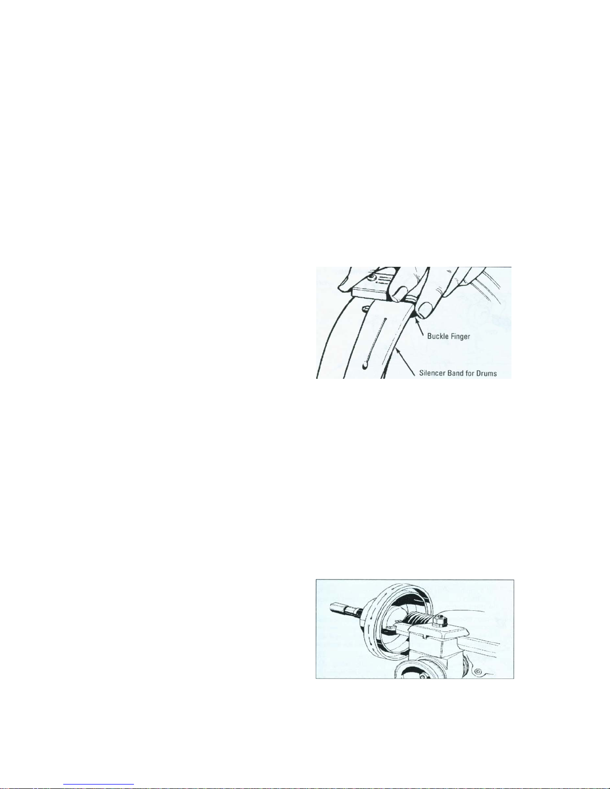
3. Wrap the drum silencer band
snugly around the drum. Be sure
it covers up to the right-hand
edge.
Figure 12-Attach silencer band
4. Position the cross slide and spindle by turning the cross feed handwheel to
maximum clockwise position. Then back off the cross feed handwheel 2
complete turns.
5. Position the boring bar by loosening the boring bar clamp nut and sliding the
boring bar inward toward the drum until the tool bit is close to the drum .
The boring bar position is changed whenever a drum of different diameter is
machined.
The entire boring bar clamp may
also be swiveled to achieve the best
cutting position.
Figure 13 - Positioning the boring bar

18
6. Turn the drum by hand to make sure that everything is clear.
7. Turn the lathe ON.
8. Advance the tool bit manually until
it just contacts the drum surface
momentarily and makes a scratch
cut.
Figure 14 - First scratch cut
9. Back the tool bit off and turn the lathe OFF.
10. Loosen the arbor nut, rotate the drum l/2 turn (180°), and retighten the nut.
11. Turn the lathe ON.
Figure 15-Typical drum mounting configurations
A. 1”Arbor B. Arbor Nut C. Self-Aligning Spacer D
.
Lathe Spindle Nose E. Spacer
F Protective Boot G. Spring H. Inside Floating Adapter I. Outside Floating Adapter
J. Centering Cone K. Large Double Taper Adapter L. Small Double Taper Adapter
Hubbed Brake Drums:Tapered cone adapters fit in the bearing seats, making contact near
the middle of the bearing race whenever possible rather than near an edge. Various
adapters and spacers maybe used to fill out the shaft of the arbor.
Hubless Brake Drums: Slip the hubless adapter onto the arbor followed by Inside Floating
Adapter, a spring, the cone, the drum, and another hubless adapter. Fill out the shaft with
spacers as needed.
Note: The self-aligning spacer should always be used next to the arbor nut when
tightening
.
To avoid over tightening
,
wrench tighten the arbor nut counterclockwise until
the drum and adapters begin to turn on the arbor, then continue to advance the wrench
1/16 of a turn
.
Do not over tighten the arbor nut.

19
12. Turn the spindle feed handwheel
1/2 turn in either direction and make
a second scratch cut. No change the
drum diameter.
Figure 16-Second scratch cut
13. Turn the lathe OFF.
14. Examine the scratch cuts.
If the first and second cuts are opposite one another (180°apart), fix wrong,
remove the drum from the arbor, check the mounting adapters and arbor for
nicks, burrs, or chips, remount the drum , and repeat scratch cut process.
If the scratches are side by side, fix right, proceed to step 15.
15. Turn the spindle feed hand-wheel until the deepest worn groove of the
drum lines up with the point of the tool bit.
16. Advance the tool bit into the bottom of the groove by rotating the cross feed
hand-wheel counter clock wise.
Note: These operations may be done with the lathe running.
In cross feed dial, one case means 0.002” (0.05mm).
17. Determine the depth-of-cut:
●Roughing cuts should be no deeper than 0.020"(0.5mm).
●Finish cuts should be no shallower than 0.004"(0.1mm).
18. With the lathe running, set the
depth-of-cut dial to the depth desired
and lock the cross feed by tightening
the lock knob.
Figure 17 – Lock cross feed
19. With the drum running by spindle motor, turn the adjusted cross move
handwheel to make cutter feeding 0.002" to 0.004".
20. Check spindle lock knob whether loosen, turn the disc/drum switch, select
the drum position, tighten the portrait move handwheel knob, auto-feed start,

20
until the cutter move to the drum outside. Turn off the drum/rotor switch and
spindle motor switch.
21. Spindle feed speed should be adjusted by feed timing potentiometer. High
speed used to roughing cut, low speed used to finish cut.
NOTE: Refer to rotor diameter to find spindle speed and feed speed. Large
diameter, you should select low speed; small diameter, you should select high
speed. “Some experimentation may be required for optimum surface
finish.”
22. When moving to the terminal
position, nut separate from the screw,
you should turn off the power switch,
turn the spindle feed handwheel
clockwise, so the screw and the nut
can mesh each other again. Screw
reset spring can do it, you can see
fig.18.
Fig18 Reconditioning Disc Brake Rotors
Preparation
1. Inspect the rotor carefully for scoring, rust ridges (at the inner and outer
circumference of the rotor), and hard spots. Any excessive wear or deformity
should be noted and if not within acceptable limits, the rotor should be
replaced.
2. Use a micrometer to check the thickness of the rotor at no less than 3
points around the circumference about 1" (2.54mm) in form the outer diameter.
If the rotor thickness varies between readings, it should be reconditioned.
However, if the thickness is less than the minimum established by the
manufacturer, or if will be less after reconditioning, the rotor should be
replaced.
Note: Most often the discard thickness dimension is cast or stamped into the
rotor, not the minimum machine to thickness.
Figure 19 – Measure rotor thickness
This manual suits for next models
1
Table of contents
Popular Lathe manuals by other brands

Handler
Handler Red Wing 26A operating manual

tornos
tornos MultiDeco Series Equipment Logbook Assembly, operation and maintenance

Haas Automation
Haas Automation Toolroom Mill Addendum

Craftsman
Craftsman 113.23881 Operating instructions and parts list

Scheppach
Scheppach DM500T Translation of original instruction manual

IGM
IGM LAGUNA 2436 operating instructions


