Far Tools ML 700 User manual

114252-D-20120301 ©FAR GROUP EUROPE
www.fartools.com
FR
EN
Metal lathe( Original version translation )
Tour à métaux ( Version originale )
Professional Machine
ML 700
114252-Manual-D-EN.indd 1 21/03/12 10:48:16

©FAR GROUP EUROPE
Huile / Oil : SAE 30-50
Après 20 jours d’utilisation / After 20 days of using.
Ajout d’huile tous les six mois ( après nettoyage ) / Re-adding every 6 months ( must be
cleaned first )
L’adjonction d’huile ne doit pas dépasser les 2/3 de la jauge / The oil adding level
souldn’t be higher than 2/3 of the oil gauge.
TRANSPORTATION AND STORAGE
Always show care when transporting or lifting the machine. Always leave this work
to qualified personnel. When loading / unloading the machine, be sure to not trap
anyone with the machine. Never pass under the machine while it is being lifted by a
crane or hoist.
Protect from damp and impacts.
The machine must be stored at temperatures of between 5°C and 45°C
LUBRIFICATION
01 17 16 15
18 14 03
114252-Manual-D-EN.indd 2 21/03/12 10:48:18

©FAR GROUP EUROPE
BALL VALVE OILER
with white spirit. Beware of the vapours that can be toxic and be sure to properly venti-
late the room. 13/ BALL VALVE OILER 14/ Using a stiff tip oil can, regularly oil those points
fitted with a ball valve oiler
LUBRICATING UNPROTECTED AREAS
Using an oiled brush, coat areas like the drive screw, the sliders, the cast iron bench...
BEFORE USE
Always let the lathe run under no load for 5 to 10 minutes so that the gearbox gears
can become lubricated
MAINTENANCE
During use, the lathe must receive regular maintenance to avoid impacting its produc-
tivity or its service life. After the first 20 days in service, drain the gearbox oil (using a
syringe not supplied). The oil is filled using the filter cap located on the top of the mo-
tor. The visual level indicator is located under the chuck (it must always be kept on the
halfway mark). Subsequently, oil changes should be made approximately every three
months (depending on frequency of use). Before starting a working session, lubricate
the machine in line with its lubrication requirements. WARNING: The oil level in the
chuck gear box must be checked regularly.
SPECIFIC SAFETY RULES
1- Always remove the chuck key from the chuck,
2- Never wear loose fitting clothing,
3- Always wear protective eye goggles,
4- Before replacing working tools or changing the speed or advance settings, always stop
the motor, disconnected the power connector and wait until the chuck has come to a
complete stop,
5- Attaching the part: Carefully attach the part before starting the lathe,
6- Stopping the lathe: Stop the lathe before taking any measurements on the part.
7- Braking: Braking the part or the chuck is dangerous
8- Eliminating chips: Never eliminate chips with your hands, always use a hook to do so.
114252-Manual-D-EN.indd 3 21/03/12 10:48:18

©FAR GROUP EUROPE
114252-Manual-D-EN.indd 4 21/03/12 10:48:29

©FAR GROUP EUROPE
MOVING AND ADJUSTING OF THE TRANSVERSE CARRIAGE
114252-Manual-D-EN.indd 5 21/03/12 10:48:30

©FAR GROUP EUROPE
MOVING AND ADJUSTING THE TAILSTOCK CENTRE
114252-Manual-D-EN.indd 6 21/03/12 10:48:32

©FAR GROUP EUROPE
N = 1000 x V
π x D
N : Rotation speed ( rpm ).
V : Cutting speed ( m.min-1 ).
D : Workpiece diameter ( mm ).
Expl : Alu ø 40 mm.
N = 1000 x 120
π x 40
N = 955
40 mm
SPEED CHOOSING
Le choix de la profondeur de passe et de la vitesse d’avance doit être basée sur la matière
de la pièce, le type de l’outil et le niveau de l’opérateur.
En alésage, la vitesse doit être diminuée de 10 à 20 %
Material Cutting tool
Steel Carbide
Steel
Soft 30-40 daN/mm230-40 m.min-1 140-300 m.min-1
40-50 daN/mm228-34 m.min-1 130-280 m.min-1
Half hard 50-60 daN/mm223-30 m.min-1 100-240 m.min-1
60-70 daN/mm220-25 m.min-1 85-200 m.min-1
Hard 70-80 daN/mm217-22 m.min-1 70-160 m.min-1
80 daN/mm2-> 12-15 m.min-1 60-120 m.min-1
Brass 40-65 m.min-1 300-600 m.min-1
Bronze 26-33 m.min-1 270-500 m.min-1
Bronze phosphorous 18-24 m.min-1 250-400 m.min-1
Aluminum 120-165 m.min-1 800-1300 m.min-1
Copper 90-125 m.min-1 600-900 m.min-1
Cast iron 15-25 m.min-1 30-100 m.min-1
114252-Manual-D-EN.indd 7 21/03/12 10:48:32

©FAR GROUP EUROPE
Gear combinations for straight turning / thread cutting
Choosing drive speeds
Positions poignées / Handle position x /min
550 970 1620
115 210 350
mm 0,2 0,25 0,3 0,35 0,4 0,45 0,5 0,6 0,7 0,75 0,8 0,9 1 1,25 1,5 1,75 2 2,5 3 3,5
A 30 55 30 35 40 45 50 60 70 40 60 50 70 75 70
B 120 75 110 80 75 110 80 35 45 35 30
C 80 50 120 80 120
D 75 110 75 60 50 45 30 35 30 60
Inch 8 9 10 11 12 13 14 16 18 20 22 24 26 28 32 36 40 48 52 56
A 60 80 60 50 60 40 50 40
B 45 75 45 60 75 60 120
C 127
D 40 60 50 55 30 65 70 80 45 50 55 60 65 70 80 45 50 60 65 70
m ∏0,2 0,25 0,3 0,4 0,5 0,6 0,7 0,8 1,0 1,25 mm 0,05 0,10
A 55 40 30 40 50 60 70 80 60 75 A 30 30
B 75 60 75 45 B 120 65
C 80 110 C 35 35
D 70 35 D 127 120
C
B
A
D
xin/
A
A
B
B
C
C
D
D
114252-Manual-D-EN.indd 8 21/03/12 10:48:36

©FAR GROUP EUROPE
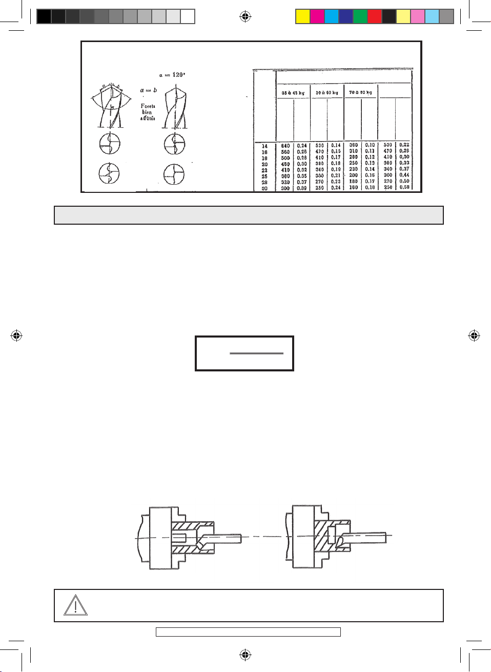
SHARPENING TOOLS
Note: The grinding head is the ideal tool for this operation. The grinding head may be
fitted with a green grinder (green silicon carbide) specially designed to sharpen carbide
tools
Metal carbides
(Cobalt, tungsten, titanium, boron combinations) These carbides that are obtained with
a special heat treatment called sintering, are used in the form of disks or “inserts”. The
latter are placed onto the tool body and attached by brazing using a special brazing
powder
LATHE TOOLS with metal carbide tabs
a, delivery angle.
. Characteristic angles: b, sharpening slope
(a+b+d=90°) d, cutting angle.
Angle values a and b
Metals and alloys to
be machined
/ Resistance R
kg/mm2
Delivery
angle a
Sharpening slope
t
Steel
up to 50 kg 6° 22 to 25°
50 to 60 kg 6° 18 to 20°
60 to 70 kg 6° 15 to 18°
70 to 80 kg 5° 12 to 15°
80 to 95 kg 5° 10 to 12°
Grey cast iron 6° 8 to 10°
Various bronzes 7° 5 to 6°
Aluminium 8° 25 to 30°
Chip breaker (Fig.2): When machining steel grades only, the tool cutting edge receives suitable
sharpening. The length l of the chip breaker varies according to the grade of steel and the pass
load:
For steel up to 50 kg/mm2.............. l= 3.5 mm
For steel of 55 to 75 kg/mm2.............. l= 3.0 mm
For steel of 80 to 95 kg/mm2.............. l= 2.5 mm
Remark. The depth or the height of the chip breaker does not vary, it is 0.5 mm (approximately).
Never heat the carbide and cool it regularly in water
Always pass the carbide plate support part over a fettling grinder.
WARNING: Always wear protective goggles while sharpening
114252-Manual-D-EN.indd 9 21/03/12 10:48:36

©FAR GROUP EUROPE
VARIOUS GRINDING/MILLING OPERATIONS
a/ Comprises removing metal from the part surface,
b/ Clamp the part into the chuck, always use the same jaw tightening square. Never let
the part protrude by more than twice its diameter (spinning in the air),
c/ Position the tool tip so that it is perfectly aligned with the part axis (to do this, use steel
shims that are placed under the tool body)
d/ Start the machine after first setting the speed in rpm.
e/ Angle the tool to the part face, push the tool back, set a cutting depth of 0.5 to 1 mm
max. by turning wheel 17 on the longitudinal carriage, then advance towards the centre
of the part by turning wheel 18 on the transverse carriage at a consistent rate.
f/ Never remove the part if it is to be corrected
g/ Where possible, lubricate using a can containing soluble oil and water and a brush.
a/ This comprises removing material over the diameter of the part,
b/ Use a cutting tool, position the tool tip perfectly in line with the part axis,
c/ Start the machine to allow automatic advance after first setting the speed in rpm
FACING
STRAIGHT TURNING
N = 1000 x V
π x D
N = 1000 x V
π x D
WARNING: Always wear protective goggles and remove the chips using a
hook, never with your hands
A right hand 45° facing tool
114252-Manual-D-EN.indd 10 21/03/12 10:48:36

©FAR GROUP EUROPE
Example:
To advance by 0.2 mm per revolution: Gear A=24, B=120, D=60, lever No. 3 on position II,
d/ Set the tool at a tangent to the part diameter. Reverse the tool to the right to escape
from the part. Set a penetration depth of 0.5 mm.
10 divisions on the Vernier callipers = 1 mm in diameter.
Start the AUTO advance function using lever No. 3 .
e/ Release at the desired moment (desired length). Be careful to allow for inertia.
f/ Reverse the tool away to the right,
g/ Stop the machine and take measurements
This operation is required before boring. It uses a drill bit. There are two kinds of drill
bits as described below. Refer to the table for more detailed explanations
Cylindrical or conical:
Cylindrical: For bits with a diameter of 0.5 to 13 mm that fit into a self tightening chuck
(option 111482).
Conical: For larger diameter bits that fit directly into the cone on the sliding headstock,
a/ Position the conical drill bit into the cone on the sliding headstock, first making sure
that the bit is properly sharpened,
b/ Start the machine after first setting the rpm,
c/ Move the tailstock centre up to the part, and lock (lever 16),
d/ Then move the bit by turning the handle smoothly.
WARNING: Avoid hitting the tool in the jaws. If the part is too long, then
you will need to fit the centred tailstock fitted with a spinning tip. Always
wear protective goggles.
Always remove the chips using a hook, never with your hands
WARNING: We recommend lubricating the part using a can containing so-
luble oil and water and a brush. For very long drilling lengths, we recom-
mend removing flashing from time to time. Before starting any drilling,
mark the centre point using a centring drill mounted in the self tightening
chuck
DRILLING
Cutter tool
114252-Manual-D-EN.indd 11 21/03/12 10:48:37
©FAR GROUP EUROPE
BORING
a/ Comprising removing matter from a hole to enlarge it so as to achieve a good surface
condition,
b/ Use a boring tool with a 45° angle to bore a through hole or make a chamfer or use a
boring-dressing tool when boring a non-though hole, bring the tool to the same height
(again using shims) as the part axis or slightly higher,
c/ Start the machine in automatic advance mode, after first setting the rpm and the
advance
Example:
Advance by 0.25 mm per revolution: Gear A=30, B=120, D=60, Lever 3 on position II,
d/ Set the tool at a tangent to the part face by turning wheel 17. Make a mark on the
Vernier callipers, then bring to a tangent inside the hole in the part by turning wheel 14.
PAY ATTENTION to the anti-clockwise direction, make a mark on the Vernier callipers.
e/ Disengage the tool from the part using wheel 17. Take a cutting depth of 1 mm per
pass off the diameter (10 divisions of the Vernier calliper for wheel 14), then regularly
advance using wheel 17 or in automatic mode by actuating lever 2. When the bore is a
through one (to bore a 10 mm depth), then have the wheel 17 Vernier callipers perform
ten turns from the point where you made a mark.
f/ Disengage the tool then take a measuremen
N = 1000 x V
π x D
WARNING: Always wear protective goggles and remove the chips using a
hook, never with your hand
Rotation speeds & advances
Helicoidal drills
angles of the edges
Steel Steel Steel
Cast iron
Metal to work
Normal cut Normal cut
Insufficient cut
Excessive cut
Boring tool angled 45 ° Boring tool - dressing tool
RPM
Advance
mm/r
Drill diameter
Advance
mm/r
Advance
mm/r
Advance
mm/r
RPM
RPM
RPM
114252-Manual-D-EN.indd 12 21/03/12 10:48:38

©FAR GROUP EUROPE
CUTTING
OUTER AND INNER THREAD CUTTING
a/ Comprises cutting a part that has already been drilled and
bored to obtain a spacer or washer,
b/ Use a cutting tool. Bring the tool tip to the same height as
the axis (again using shims) or a little below the part centre,
c/ Start the machine after first setting the rpm,
d/ Offset your tool to the left (wheel 17) using a straight edge to check the distance
between the part face and the right hand side of your tool. Stop as soon as you obtain
the desired distance and add 1 mm to it to correct the face surface.
e/ Manually and regularly advance the tool using wheel 14. We recommend lubricating
(with soluble oil and water) using a brush. As soon as the tool drills through into the
bore, reverse and disengage to the right
Designation: Threads are designated by the M symbol, followed by their diameter and
pitch in mm, separated by a multiplication sign. Example: M 30 x 3.5, i.e. M 30 for a 30
diameter thread with a 3.5 mm thread pitch. Standard threads are:
/ Outer thread: The tool profile sharpening angle for cutting a metric thread is 60°, The
tool profile sharpening angle for cutting a Whitworth thread (English pitch) is 55°,
CUTTING A TRIANGULAR THREAD
Tool penetration
- Normal penetration (see Fig. below).
The tools are aimed and their profiles sharpened to 60°
or 55° using angle centre gages.
Tool height position. Absolutely aligned with the tip
axes (part axis).
nominal Diameter M Typical pitch P (mm)
M 3 0,6
M 4 0,7
M 5 0,8
M 6 1
M 8 1,25
M 10 1,50
M 12 1,75
M 14 2
M 16 2
M 18 2,5
M 20 2,5
M 22 2,5
M 24 3
M 27 3
M 30 3,5
N = 1000 x V
π x D
Outer
threading
tool
Outer threa-
ding tool
Cutting tool
114252-Manual-D-EN.indd 13 21/03/12 10:48:38
©FAR GROUP EUROPE
The tool is aligned with the part using a centre gage. This centre gage is useful when
checking tool sharpening.
1/ Once the tool is correctly sharpened and aligned, set the rpm, a setting that will be far
slower than the theoretical rpm rate, (approx. 50% less).
Example: For an M 20 x 2.5, semi-hard steel=30
setting that will be far slower than the theoretical rpm rate, (approx. 50% less).
Example: For an M 20 x 2.5, semi-hard steel=30 132/ To cut a thread, a speed of 220 rpm
will be used
2/ Then the pitch will be set by changing the gears. For a 2.5 mm pitch, the choice will be
A=60 teeth, B=120 teeth and D=24 teeth and lever 3 will be set to I,
3/ Before starting machining, calculate the tool penetration depth using the following
formula:
Example:
For a 2.5 mm pitch: 0.61 x 2.5 = 1.525 mm in radius
4/ Pull the part far enough out of the chuck when cutting a thread so that no collision
occurs between the thread cutting tools and the chuck jaws (as the chuck does not have
a brake). The technique used to stop thread cutting is first of all to shutdown the motor
and then to quickly withdraw the tool.
5/ Start up. Place the tool at a tangent to the part. The part has a nominal diameter of
20. For an M 20 x 2.5 mm thread, make a pencil mark on the Vernier callipers. Disengage
the tool to the right on removing it from the part.
Take a 0.5 mm cutting depth (for the first pass only), i.e. 10 divisions on the Vernier cal-
lipers. Stop the machine.
Engage lever 2 (leadscrew clutch),
Lubricate the part with cutting oil.
Start up and place one hand on wheel 14 to disengage the tool when it reaches the de-
sired thread length, then place the other hand on the motor stop button.
Reverse the machine to return the tool to its starting position, and start another 0.25
pass (5 divisions on the Vernier calliper in addition to the 10 divisions already taken du-
ring the first pass)
- Repeat the operation six times to achieve the theoretical 1.525 cutting depth.
- After the final pass, perform one more blank pass to correct tool part flex,
- Back off the tailstock centre and try the thread with a 20 mm 2.5 pitch nut.
Pdp = 0,61 x P
N = 1000 x 30 = 477 tr/ min
π x 20
WARNING: Do not disengage lever 2 for the tool may no longer fit into
the same pitch during the next pass.
114252-Manual-D-EN.indd 14 21/03/12 10:48:38

©FAR GROUP EUROPE
Inner thread:
- When cutting an inner thread, the speed remains the same for an equivalent diameter,
- The gear settings are the same. Nevertheless, you need to calculate the bore diameter
and penetration depth. To do this, use the following formulas:
The other hand remains in place on the machine stop button
Tighten the part into the chuck - Bore to a diameter of 17.3 mm, Raise and rigorously
position the tool by bringing it out by twice the length to be machined, for once again
there is no footbrake available for use,
Start up the machine and place the tool at a tangent to the bore,
Disengage the tool to the right on removing it from the part, Take a 0.5 mm cutting
depth (for the first pass only), i.e. 10 divisions on the Vernier callipers, Stop the machine,
engage lever 2 (leadscrew clutch),
Lubricate the part with cutting oil,
Start up and place one hand on wheel 14 to disengage the tool (when it reaches the
desired thread length or the end of the bore, for a full length thread).
BORE DIAMETER FOR A THREAD OF
M 20 X 2,5 =
D - ( 1,08 x P ) =
20 - ( 1,08 x 2,5 ) = 17,3
PENETRATION DEPTH FOR A 2.5 MM PITCH:
0,577 X P
0,577 X 2,5 = 1,3925 to radius
WARNING: To disengage the tool, turn the wheel clockwise for an inner
thread
External
thread on the
right
114252-Manual-D-EN.indd 15 21/03/12 10:48:39

©FAR GROUP EUROPE
WARNING: Never release lever 2 until the thread cutting is finished
To reset the tool in the start position, reverse the chuck direction and repeat a number of
0.25 mm passes to achieve the final 1.3925 mm dimension, Try the M 20 x 2.5 bolt before
disengaging the centre gage lever 2
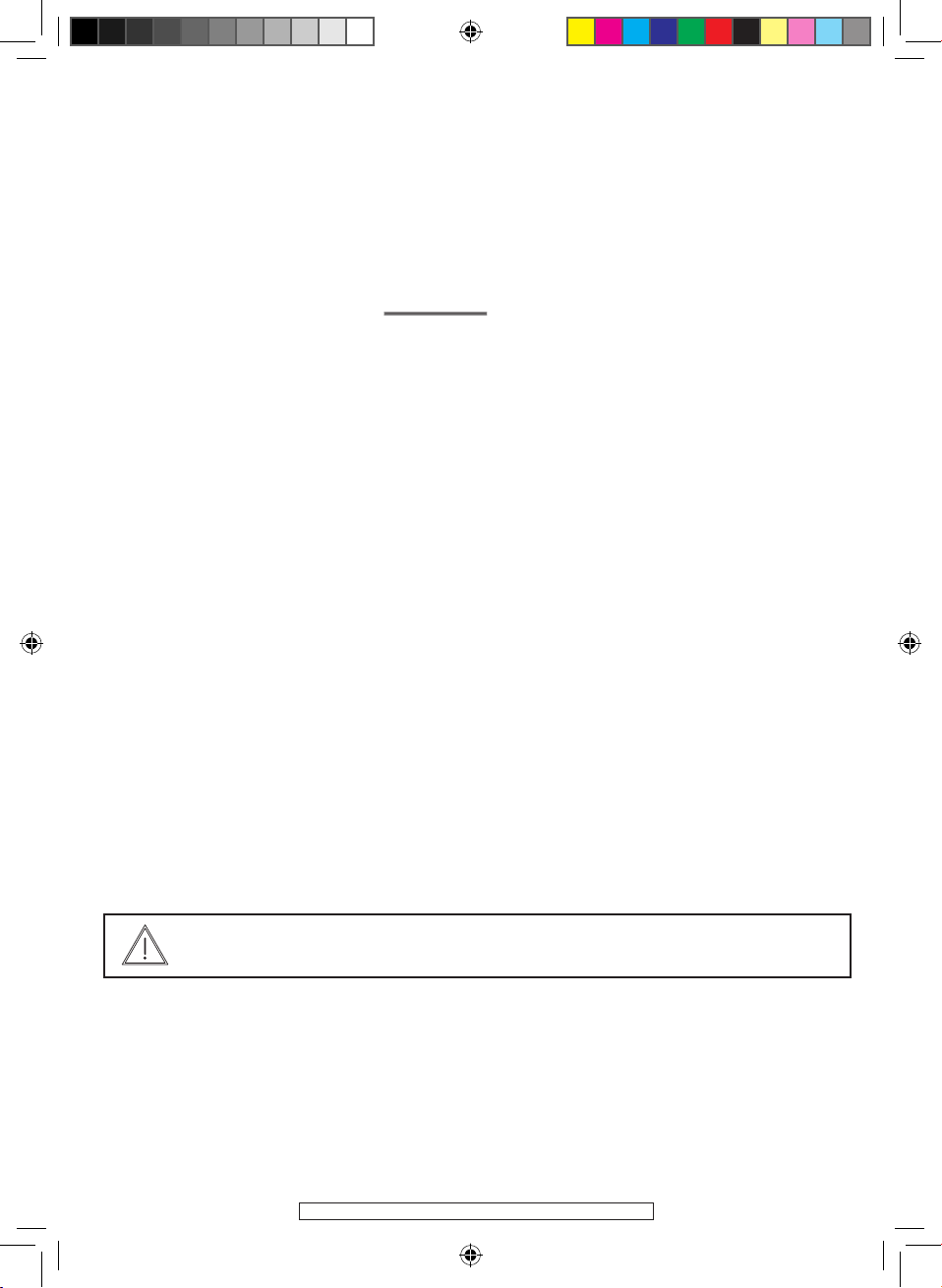
The mixed fitting mode is used when the part, once clamped in the chuck, protrudes
from it by more than twice its diameter.
Tighten the part in the chuck, Drill a centre hole using a centring bit, Then bring up
the tailstock centre (114317), the mounting is a rigid one and it is possible to safely ma-
chine.
The fitting between tailstocks mode is used to produce axes that require perfect concen-
tricity between all diameters. To do this, it is necessary to drill a centre hole through both
ends of the axis to be machined. Then take the chuck apart and fit the dry tailstock and
place the part to be milled between the dry tailstock and the spinning one (114317).
Drive is achieved with a toc
MIXED FITTING
FITTING BETWEEN TAILSTOCKS
OTHER MILLING MODES
Metric
threading
114252-Manual-D-EN.indd 16 21/03/12 10:48:39

©FAR GROUP EUROPE
A steady is used when machining very long axes and when the tailstock centre can be
used. The steady is mounted on the longitudinal carriage and the brass pads or ball
bearings are positioned on the opposite side to the tool. This avoids vibration (therefore
ensuring good quality machining).
A fixed steady is used when machining very only axes when the tailstock centre cannot
be used (boring, thread cutting). The fixed steady is mounted on the bench between the
chuck and the tool carrier carriage
FITTING WITH A STEADY (OPTION 114300)
MOUNTING WITH A FIXED STEADY (OPTION 114320
fitting between tailstocks
fitting with a
steady
steady
fixed
steady
fitting with a
fixed steady
114252-Manual-D-EN.indd 17 21/03/12 10:48:40

©FAR GROUP EUROPE
X
Lire les instructions avant usage : Внимательно прочитайте следующие инструкции :
X
Read the instructions before use : Kullanmadan talimatlari okuyunuz :
Vor Einsatz des Geräts Anweisung lesen : Pozorně si přečtěte následující pokyny :
Léase las instrucciones antes de usar : Pred použitím si precítajte pokyny :
Leggere le istruzioni prima dell’uso : יפוליח םרז
Ler as instruções antes da utilização : .مادختسالا لبق تاميلعتلا أرقا
Lees voor het gebruik de instructies : használat elott olvassuk el az utasítást :
: Pred uporabo preberite ustrezna navodila :
Zapoznać sięz instrukcją przed użyciem : Прочетете указанията за употреба :
Lue ohjeet ennen käyttöä : Enne kasutamist lugege instruktsiooni
Läs anvisningarna före användning : Prieš naudojimą perskaityti instrukciją
læs instruktionerne før brug izlasīt instrukcijas pirms lietošanas
Înainte de utilizare, cititi instructiunile :
Conformité européenne соответствие европейским стандартам:
X
Conforms to EC standards : Avrupa uygunluk :
CE-Konformität : evropská shoda :
Cumple con las directivas CE : európska dohoda :
Conforme alle norme CE : םייפוריאהםינקתל המאתה
Conforme às normas CE : .ةيبوروألا تافصاوملل قباطم
Voldoet aan de EG-normen : evropska ustreznost :
európai megfelelőség :
Zgodność z normami CE : Съответствие с европейските норми :
EU-standardien mukainen : Euroopa Liidu vastavusmärk
EU-standardien mukainen : Europinių normų atitikima
Overholder EU standarderne : Atbilstība Eiropas standartiem
Conform cu normele europene:
Danger : Опасно :
X
Danger : Tehlike :
Gefahr : Nebezpečí :
Peligro : Nebezpečenstvo :
Pericolo : .הנכס
Perigo : .رطخ
Gevaar : Veszély :
: Nevarnost:
Niebezpieczńestwo : Опасност :
Vaara : Oht
Fara : Pavojus
Fare : Bīstamība
Pericol :
114252-Manual-D-EN.indd 18 21/03/12 10:48:43

©FAR GROUP EUROPE
Porter une protection auditive: наденьте средства звуковой защиты:
X
Wear hearing protective equipment: İşitsel koruma aleti takın:
Gehörschutz tragen: Používejte ochranu sluchu:
Llevar puesta una protección auditiva: Noste ochranné slúchadlá:
Portare una protezione uditiva: העימש תנגה ביכרה ל שי
Utilizar uma protecção auditiva: .جيجضلا ضض ةذوخ سبل
Draag gehoorbeschermers: Viseljen fülvédőt
Nositi zašito ušes:
Zakładać słuchawki ochronne Да се използва слухови защитни средства:
Käytä kuulosuojaimia: Kandke kõrvakaitset
Bär hörselskydd: Nešioti apsaugą nuo triukšmo
Der skal benyttes høreværn: valkāt dzirdes aizsarglīdzekli
Purtaţi căşti de protecţie auz:
Porter un masque anti-poussière: Наденьте респиратор :
X
Wear a dust mask : Toza karşı maske takın :
Staubschutzmaske tragen : Používejte masku proti prachu :
Llevar puesta una careta de protección contra el polvo : Noste ochrannú masku proti prachu :
Indossare una mascherina anti-polvere : נא לחבוש מסכה נגד אבק.
Utilizar uma máscara anti-poeira : .رابغلل ضاضم عانق سبل
Draag een stofmasker : Viseljen porvédő maszkot
χρήση προστατευτική µάσκα :Nositi zaščitno masko proti prahu:
Zakładać maskę przeciwpyłową Да се използва защитна маска :
Käytä pölysuojust : Kandke tolmumaski.
Bär mask mot damm : Dėvėti respiratorių
Der skal benyttes beskyttelsesmaske mod støv: Valkāt aizsarg masku pret putekļiem
Purtaţi mască anti-praf :
Porter des lunettes de sécurité : Наденьте защитные очки :
X
Wear protective eyewear : Güvenlik gözlükleri takın :
Schutzbrille tragen : Používejte bezpečnostní brýle :
Llevar puestas gafas protectoras : Noste ochranné okuliare :
Portare de gli occhiali di sicurezza : נא להרכיב משקפי בטיחות.
Utilizar óculos de segurança : .ةياقو تاراظن لَمح
Draag een veiligheidsbril : Viseljen védőszemüveget :
: Nositi zaščitna očala :
Zakładać okulary ochronne :Да се използват защитни очила :
Käytä suojalaseja : Kandke kaitseprille
Använd skyddsglasögon :Nešioti apsauginius akinius
Der skal benyttes sikkerhedsbriller : Valkāt aizsargbrilles
Purtaţi ochelari de protecţie :
114252-Manual-D-EN.indd 19 21/03/12 10:48:45

©FAR GROUP EUROPE
Niveau de puissance acoustique : уровень мощности звука :
117 dB (A)
Acoustic power level : Akustik basınç seviyesi :
Schallleistungspegel : Hladina zvukového výkonu:
Nivel de potencia acústica : Hladina zvukového výkonu:
Livello di potenza acustica: .יטסוקא חוכ תמר
Nível de potência acústica: .جيجضلا ىوتسم
Niveau akoestisch vermogen : a hangnyomás szintje :
: Nivo akustične jakosti :
Poziom mocy akustycznej : Равнище на вибрации :
Käytä suojalaseja : Helivõimsuse nivoo
Ljudstyrkenivå : Triukšmo lygis
Lydstyrke : Akustiskās jaudas līmenis
Nivel putere acustică :
NIVEAU SONORE D’EMISSION: A VIDE
Pression acoustique LpA poste opérateur 103 dB
Incertitude 3
Puissance acoustique LWA 117 dB
Incertitude 3
Valeurs déterminées suivant le code d’essai de l’annexe B de la norme EN 61029-1 avec emploi des normes de base ISO 11201 et ISO
3744.
Les niveaux de pression acoustique obtenus in situ dépendent:
- Des niveaux réels de la machine considérées, en prenant en compte les incertitudes déclarées;
- Du local et de l’installation de la machine. Préférez une pièce dont l’acoustique est plus feutrée. Evitez les pièces vide à grande réson-
nance. Placez vous auprès d’une fenètre le cas échéant.
- Des outils montés, des pièces travaillées, des réglages choisis,...
Niveau de pression acoustique : Уровень акустического давления. :
103 dB (A)
Acoustic pressure level : Akustik basınç seviyesi :
Schalldruckpegel : Hladina akustického tlaku :
Nivel de presión acústica : Hladina akustického tlaku :
Livello di pressione acustica : .יטסוקא ץחל תמר
Nível de pressão acústica : .يعمسلا طغضلا ىوتسم
Niveau akoestische druk : A hangnyomás szintje :
: Nivo akustičnega pritiska:
Poziom mocy akustycznej : Равнище на акустично налягане :
Käytä kuulosuojaimia: Helirõhu nivoo
Ljudtrycksnivå : Akustinio spaudimo lygis
Lydtryk : Akustiskā spiediena līmenis
Nivel presiune acustică :
114252-Manual-D-EN.indd 20 21/03/12 10:48:45
Other manuals for ML 700
1
Table of contents
Other Far Tools Lathe manuals


