Steelex ST1008 User manual

#18045DN
Phone: (360) 734-3482 • Online Technical Support: [email protected]
COPYRIGHT © MARCH, 2016 BY WOODSTOCK INTERNATIONAL, INC. REVISED MARCH, 2017 (HE)
WARNING: NO PORTION OF THIS MANUAL MAY BE REPRODUCED IN ANY SHAPE OR FORM WITHOUT
THE WRITTEN APPROVAL OF WOODSTOCK INTERNATIONAL, INC. Printed in China
MODEL ST1008
MINI WOOD LATHE
OWNER'S MANUAL
For Models Manufactured Since 06/16
V2.03.17

Some dust created by power sanding, sawing, grinding, drilling, and
other construction activities contains chemicals known to the State of
California to cause cancer, birth defects or other reproductive harm.
Some examples of these chemicals are:
• Lead from lead-based paints.
• Crystalline silica from bricks, cement and other masonry products.
• Arsenic and chromium from chemically-treated lumber.
Your risk from these exposures varies, depending on how often you
do this type of work. To reduce your exposure to these chemicals:
Work in a well ventilated area, and work with approved safety equip-
ment, such as those dust masks that are specially designed to lter
out microscopic particles.
This manual provides critical safety instructions on the proper setup,
operation, maintenance, and service of this machine/tool. Save this docu-
ment, refer to it often, and use it to instruct other operators.
Failure to read, understand and follow the instructions in this manual may
result in re or serious personal injury—including amputation, electrocu-
tion, or death.
The owner of this machine/tool is solely responsible for its safe use. This
responsibility includes but is not limited to proper installation in a safe
environment, personnel training and usage authorization, proper inspec-
tion and maintenance, manual availability and comprehension, applica-
tion of safety devices, cutting/sanding/grinding tool integrity, and the
usage of personal protective equipment.
The manufacturer will not be held liable for injury or property damage
from negligence, improper training, machine modications or misuse.

Table of Contents
INTRODUCTION .................................................... 2
Contact Info.................................................................... 2
Manual Accuracy .......................................................... 2
Identification.................................................................. 5
Controls & Features...................................................... 6
SAFETY .................................................................. 7
Safety Instructions for Machinery .......................... 7
Additional Safety for Wood Lathes........................ 9
ELECTRICAL......................................................... 10
Circuit Requirements ................................................10
Grounding Requirements .......................................11
Extension Cords ..........................................................11
SETUP .................................................................. 12
Unpacking.....................................................................12
Inventory .......................................................................12
Cleanup..........................................................................13
Site Considerations....................................................13
Assembly .......................................................................14
Test Run..........................................................................15
OPERATIONS ....................................................... 16
Overview .......................................................................16
Stock Inspection & Requirements........................17
Adjusting Tailstock.....................................................19
Adjusting Tool Rest ....................................................19
Installing/Removing Spur Center.........................20
Installing/Removing Live Center ..........................21
Installing/Removing Faceplate..............................21
Selecting Turning Tools............................................22
Spindle Turning...........................................................23
Faceplate Turning.......................................................24
Sanding/Finishing ......................................................25
ACCESSORIES ...................................................... 26
Lathe Accessories .......................................................26
MAINTENANCE.................................................... 27
General...........................................................................27
Cleaning.........................................................................27
Unpainted Cast Iron ..................................................27
Changing Belt..............................................................27
Lubrication....................................................................27
SERVICE ............................................................... 28
Troubleshooting .........................................................28
Wiring Diagram...........................................................30
PARTS................................................................... 31
Main.................................................................................31
Main Parts List .............................................................32
Labels & Cosmetics....................................................33
WARRANTY.......................................................... 34
Warranty Registration...............................................35

-2- ST1008 Mini Wood Lathe
We are proud to provide a high-quality owner’s man-
ual with your new machine!
We made every effort to be exact with the instruc-
tions, specifications, drawings, and photographs
contained inside. Sometimes we make mistakes, but
our policy of continuous improvement also means
that sometimes the machine you receive will be
slightly different than what is shown in the man-
ual.
If you find this to be the case, and the difference
between the manual and machine leaves you
confused about a procedure, check our website
for an updated version. We post current manuals
and manual updates for free on our website at
www.woodstockint.com.
Alternatively, you can call our Technical Support for
help. Before calling, make sure you write down the
Manufacture Date and Serial Number from the
machine ID label (see below). Also, if available, have
a copy of your original purchase receipt on hand.
This information is required for all Tech Support calls.
MODEL XXXX
MACHINE NAME
Motor:
Specification:
Specification:
Specification:
Specification:
Weight:
Specifications
To reduce risk of serious personal injury when using this
machine:
1. Read & understand owner’s manual before operating.
2. Always wear approved eye protection and respirator.
3. Only plug power cord into a grounded outlet.
4. Only use this machine to collect wood dust/chips—never
use to collect glass, metal, liquids, asbestos, silica,
animal parts, biohazards, burning material/ashes, etc.
5. Always disconnect power before servicing or cleaning.
6. Do not expose to rain or wet areas.
7. Keep hands, long hair, and loose clothing away from
inlet.
8. Never leave machine unattended while it is running.
9. Do not use if cord/plug becomes damaged—promptly
repair and protect cord from future damage.
10. Do not use without dust bag or filters in place.
11. Always wear a respirator when emptying bags.
12. Prevent unauthorized use by children or untrained users.
Date
Serial Number
Manufactured for Woodstock in Taiwan
WARNING!
Manufacture
Date
Serial Number
We are committed to customer satisfaction. If you
have any questions or need help, use the information
below to contact us.
IMPORTANT: Before contacting, please get the
original purchase receipt, serial number, and
manufacture date of your machine. This informa-
tion is required for all Technical Support calls and
it will help us help you faster.
Woodstock International Technical Support
Phone: (360) 734-3482
Email: [email protected]
We want your feedback on this manual. What did
you like about it? Where could it be improved?
Please take a few minutes to give us feedback.
Technical Documentation Manager
P.O. Box 2309
Bellingham, WA 98227
Email: [email protected]
INTRODUCTION
Contact Info Manual Accuracy

ST1008 Mini Wood Lathe -3-
© Woodstock International, Inc. • Phone: (800) 840-8420 • Web: www.woodstockint.com
MACHINE
SPECIFICATIONS
MODEL ST1008
10" X 15" BENCHTOP WOOD LATHE
Product Dimensions:
Weight ........................................................................................................................................................................................................................92 lbs.
Length x Width x Height ............................................................................................................................................................... 34 x 8-3/4 x 15 in.
Footprint (Length x Width) .....................................................................................................................................................................33 x 8-3/4 in.
Shipping Dimensions
Type.............................................................................................................................................................................................................Cardboard Box
Content .................................................................................................................................................................................................................. Machine
Weight .........................................................................................................................................................................................................................98 lbs.
Length x Width x Height......................................................................................................................................................................38 x 12 x 16 in.
Electrical:
Power Requirement.........................................................................................................................................................120V, Single-Phase, 60 Hz
Prewired Voltage........................................................................................................................................................................................................ 120V
Full-Load Current Rating..............................................................................................................................................................................................6A
Minimum Circuit Size..................................................................................................................................................................................................15A
Connection Type...........................................................................................................................................................................................Cord & Plug
Power Cord Included ...................................................................................................................................................................................................Yes
Power Cord Length......................................................................................................................................................................................................6 ft.
Power Cord Gauge...............................................................................................................................................................................................18 AWG
Plug Included..................................................................................................................................................................................................................Yes
Included Plug Type .....................................................................................................................................................................................................5-15
Switch Type............................................................................................................................................. Paddle Safety Switch w/Removable Key
Motor:
Type............................................................................................................................................................................ TEFC Capacitor-Start Induction
Horsepower..............................................................................................................................................................................................................1/2 HP
Phase...............................................................................................................................................................................................................Single-Phase
Amps...................................................................................................................................................................................................................................6A
Speed................................................................................................................................................................................................................... 1725 RPM
Power Transfer...................................................................................................................................................................................................Belt Drive
Bearings ........................................................................................................................................................... Shielded & Permanently Lubricated
Main Specications:
Operation
Swing Over Bed............................................................................................................................................................................................10 in.
Distance Between Centers .......................................................................................................................................................................15 in.
Max. Distance Tool Rest to Spindle Center...................................................................................................................................3-3/4 in.
Number of Spindle Speeds ..............................................................................................................................................................................6
Spindle Speed Range ........................................................................................................................................................... 480 – 4023 RPM
Floor to Center Height .................................................................................................................................................................... 13-5/32 in.
Model ST1008 Machine Specifications, Page 1 of 2

-4- ST1008 Mini Wood Lathe
Spindle Information
Spindle Taper................................................................................................................................................................................................ MT#2
Spindle Thread Size............................................................................................................................................................................. 1" x 8 TPI
Spindle Thread Direction ............................................................................................................................................................. Right-Hand
Spindle Bore...........................................................................................................................................................................................2-3/64 in.
Type of Included Spindle Center............................................................................................................................................................. Spur
Tailstock Information
Tailstock Taper.............................................................................................................................................................................................. MT#2
Typer of Included Tailstock Center.......................................................................................................................................................... Live
Construction
Bed .........................................................................................................................................................................Precision-Ground Cast Iron
Frame..........................................................................................................................................................................................Cast Iron & Steel
Headstock.................................................................................................................................................................................Cast Iron & Steel
Tailstock.....................................................................................................................................................................................Cast Iron & Steel
Paint Type/Finish......................................................................................................................................................................................Enamel
Other Related Information
Bed Width ...............................................................................................................................................................................................8-3/16 in.
Faceplate Size..................................................................................................................................................................................................3 in.
Other Information
Country of Origin........................................................................................................................................................................................China
Warranty.......................................................................................................................................................................................................2 Years
Approximate Assembly & Setup Time......................................................................................................................................15 Minutes
Serial Number Location....................................................................................................................................................................... ID Label
ISO 9001 Factory ...............................................................................................................................................................................................No
Certified by a Nationally Recognized Testing Laboratory (NRTL) ..................................................................................................Yes
Model ST1008 Machine Specifications, Page 2 of 2
ST1008 Mini Wood Lathe -5-
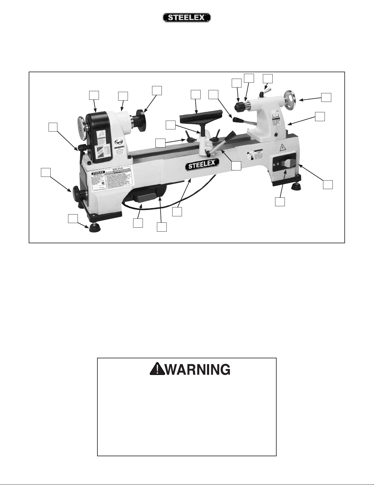
Identification
L
A. Belt Tension Lock Knob
B. Belt Cover Lock Handle
C. Spindle Cover
D. Headstock
E. Faceplate
F. Tool Rest Lock Handle
G. Tool Rest Base
H. Tool Rest
I. Tool Rest Release Lever
J. Tailstock Lock Lever
K. Live Center
L. Quill
M. Quill Lock Handle
N. Quill Handwheel
O. Tailstock
P. ON/OFF Switch
Q. Safety Key
R. Lathe Bed
S. Motor
T. Belt Tension Lever
U. Foot
Figure 1. ST1008 identification.
A
F
P
Q
R
S
U
I
J
KM
N
O
B
CDE
G
H
T
For Your Own Safety Read Instruction Manual Before
Operating Lathe
a) Wear eye protection.
b) Do not wear gloves, necktie, or loose clothing.
c) Tighten all locks before operating.
d) Rotate workpiece by hand before applying power.
e) Rough out workpiece before installing on faceplate.
f) Do not mount split workpiece or one containing knot.
g) Use lowest speed when starting new workpiece.
Become familiar with the names and locations of the controls and features shown below to better understand the
instructions in this manual.
-6- ST1008 Mini Wood Lathe
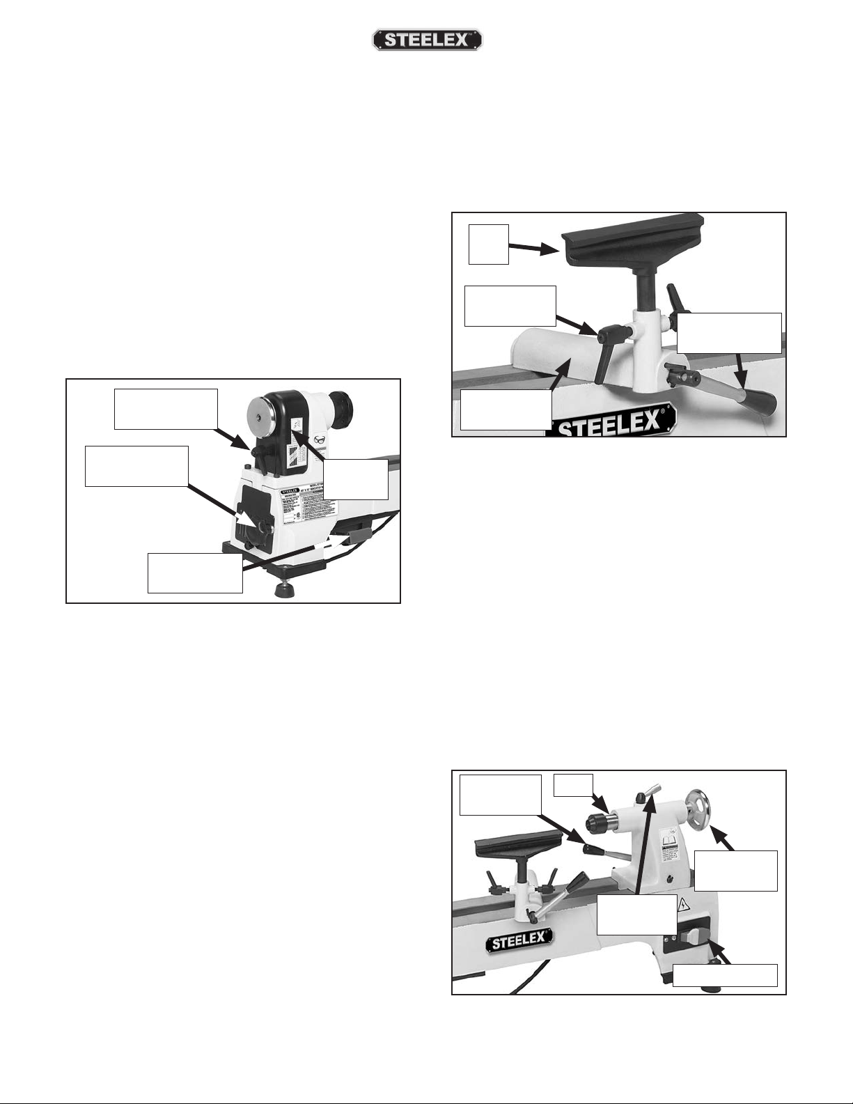
Controls & Features
Use descriptions and following figures to become
familiar with basic controls of your lathe.
Belt Cover Lock Handle: Removes the belt cover
when loosened.
Belt Tension Lock Knob: Locks or unlocks belt ten-
sion lever.
Belt Tension Lever: Adjusts belt tension.
Spindle Cover: Protective cover over belt and spin-
dle pulley. Remove to change belt position on pulleys
for adjusting spindle speed.
Tailstock Lock Lever: Unlocks tailstock to allow
quick position adjustments along lathe bed.
Tailstock Quill: Holds centers or tooling. Can be
moved toward and away from spindle.
Quill Handwheel: Moves tailstock quill in and out
to allow clamping or releasing of workpiece held
between spindle center and tailstock center.
Quill Lock Handle: Locks quill in place to prevent
loosening during operation of lathe.
ON/OFF Switch: Turns power ON/OFF to lathe motor,
which rotates spindle.
Figure 4.Tailstock controls.
Quill
Quill
Handwheel
ON/OFF Switch
Quill Lock
Handle
Tailstock
Lock Lever
Figure 2. Belt tension controls.
Belt Tension
Lock Knob Spindle
Cover
Belt Tension
Lever
Belt Cover
Lock Handle
Figure 3. Tool rest controls.
Tool
Rest
Tool Rest
Lock Handle Tool Rest
Release Lever
Tool Rest: Provides a stable resting position for turn-
ing tools.
Tool Rest Lock Handle: Locks tool rest in position
relative to tool rest base.
Tool Rest Release Lever: Lock and unlocks tool rest
base and allows it to be repositioned along lathe bed.
Tool Rest
Base (Banjo)

ST1008 Mini Wood Lathe -7-
SAFETY
ELECTRICAL EQUIPMENT INJURY RISKS. You can
be shocked, burned, or killed by touching live elec-
trical components or improperly grounded machin-
ery. To reduce this risk, only allow qualified service
personnel to do electrical installation or repair work,
and always disconnect power before accessing or
exposing electrical equipment.
DISCONNECT POWER FIRST.
Always disconnect
machine from power supply BEFORE making adjust-
ments, changing tooling, or servicing machine. This
prevents an injury risk from unintended startup or
contact with live electrical components.
EYE PROTECTION. Always wear ANSI-approved safe-
ty glasses or a face shield when operating or observ-
ing machinery to reduce the risk of eye injury or
blindness from flying particles. Everyday eyeglasses
are NOT approved safety glasses.
OWNER’S MANUAL. Read and understand this own-
er’s manual BEFORE using machine.
TRAINED OPERATORS ONLY.Untrained operators
have a higher risk of being hurt or killed. Only
allow trained/supervised people to use this machine.
When machine is not being used, disconnect power,
remove switch keys, or lock-out machine to prevent
unauthorized use—especially around children. Make
workshop kid proof!
DANGEROUS ENVIRONMENTS. Do not use machin-
ery in areas that are wet, cluttered, or have poor
lighting. Operating machinery in these areas greatly
increases the risk of accidents and injury.
MENTAL ALERTNESS REQUIRED. Full mental alert-
ness is required for safe operation of machinery.
Never operate under the influence of drugs or alco-
hol, when tired, or when distracted.
For Your Own Safety, Read Instruction Manual
Before Operating This Machine
The purpose of safety symbols is to attract your attention to possible hazardous conditions. This
manual uses a series of symbols and signal words intended to convey the level of importance of the
safety messages. The progression of symbols is described below. Remember that safety messages
by themselves do not eliminate danger and are not a substitute for proper accident prevention mea-
sures. Always use common sense and good judgment.
Indicates a potentially hazardous situation which, if not avoided, MAY
result in minor or moderate injury. It may also be used to alert against
unsafe practices.
Indicates a potentially hazardous situation which, if not avoided, COULD
result in death or serious injury.
Indicates an imminently hazardous situation which, if not avoided, WILL
result in death or serious injury.
This symbol is used to alert the user to useful information about proper
operation of the machine.
NOTICE
Safety Instructions for Machinery

-8- ST1008 Mini Wood Lathe
WEARING PROPER APPAREL. Do not wear cloth-
ing, apparel or jewelry that can become entangled
in moving parts. Always tie back or cover long hair.
Wear non-slip footwear to reduce risk of slipping and
losing control or accidentally contacting cutting tool
or moving parts.
HAZARDOUS DUST. Dust created by machinery
operations may cause cancer, birth defects, or long-
term respiratory damage. Be aware of dust hazards
associated with each workpiece material. Always
wear a NIOSH-approved respirator to reduce your
risk.
HEARING PROTECTION. Always wear hearing pro-
tection when operating or observing loud machin-
ery. Extended exposure to this noise without hearing
protection can cause permanent hearing loss.
REMOVE ADJUSTING TOOLS. Tools left on machin-
ery can become dangerous projectiles upon startup.
Never leave chuck keys, wrenches, or any other tools
on machine. Always verify removal before starting!
USE CORRECT TOOL FOR THE JOB. Only use this
tool for its intended purpose—do not force it or an
attachment to do a job for which it was not designed.
Never make unapproved modifications—modifying
tool or using it differently than intended may result
in malfunction or mechanical failure that can lead to
personal injury or death!
AWKWARD POSITIONS. Keep proper footing and
balance at all times when operating machine. Do
not overreach! Avoid awkward hand positions that
make workpiece control difficult or increase the risk
of accidental injury.
CHILDREN & BYSTANDERS. Keep children and
bystanders at a safe distance from the work area.
Stop using machine if they become a distraction.
GUARDS & COVERS. Guards and covers reduce acci-
dental contact with moving parts or flying debris.
Make sure they are properly installed, undamaged,
and working correctly BEFORE operating machine.
FORCING MACHINERY. Do not force machine. It will
do the job safer and better at the rate for which it was
designed.
NEVER STAND ON MACHINE. Serious injury may
occur if machine is tipped or if the cutting tool is
unintentionally contacted.
STABLE MACHINE. Unexpected movement during
operation greatly increases risk of injury or loss of
control. Before starting, verify machine is stable and
mobile base (if used) is locked.
USE RECOMMENDED ACCESSORIES. Consult this
owner’s manual or the manufacturer for recom-
mended accessories. Using improper accessories will
increase the risk of serious injury.
UNATTENDED OPERATION. To reduce the risk of
accidental injury, turn machine OFF and ensure all
moving parts completely stop before walking away.
Never leave machine running while unattended.
MAINTAIN WITH CARE. Follow all maintenance
instructions and lubrication schedules to keep
machine in good working condition. A machine that
is improperly maintained could malfunction, leading
to serious personal injury or death.
DAMAGED PARTS. Regularly inspect machine for
damaged, loose, or mis-adjusted parts—or any con-
dition that could affect safe operation. Immediately
repair/replace BEFORE operating machine. For your
own safety, DO NOT operate machine with damaged
parts!
MAINTAIN POWER CORDS. When disconnecting
cord-connected machines from power, grab and pull
the plug—NOT the cord. Pulling the cord may dam-
age the wires inside. Do not handle cord/plug with
wet hands. Avoid cord damage by keeping it away
from heated surfaces, high traffic areas, harsh chemi-
cals, and wet/damp locations.
EXPERIENCING DIFFICULTIES. If at any time you
experience difficulties performing the intended oper-
ation, stop using the machine! Contact our Technical
Support at (570) 546-9663.

ST1008 Mini Wood Lathe -9-
Additional Safety for Wood Lathes
MAIN INJURY HAZARDS: Death or crushing injury from getting entangled in rotating spindle or
workpiece; death, blindness, or broken bones from being struck by a workpiece that breaks apart
or comes loose during rotation, turning tool kickback, or flying wood chips. To minimize your risk of
these hazards, always heed the following warning information:
EYE/FACE PROTECTION.Always wear a face shield
and safety glasses when operating lathe.
PROPER APPAREL.Do not wear gloves, necktie or
loose clothing. Keep long hair away from rotating
spindle.
SPEED RATES. Select correct spindle speed for
workpiece size, type, shape, and condition. Use
low speeds when roughing or when turning large,
long, or non-concentric workpieces. Allow spindle to
reach full speed before turning.
NEW SETUPS. Test each new setup by starting spin-
dle rotation at the lowest speed and standing to the
side of the lathe until workpiece reaches full speed
and you can verify safe rotation.
ROUGHING. Use correct tool. Take light cuts, use
low speeds, and firmly support tool with both hands.
SHARP TOOLS.Only use sharp turning tools— they
cut with less resistance than dull tools. Dull turning
tools can catch or grab and pull your hands into the
rotating workpiece.
STOPPING SPINDLE.Always allow spindle to com-
pletely stop on its own. Never put hands or another
object on spinning workpiece.
ADJUSTMENT/MAINTENANCE.Make sure wood
lathe is turned OFF, disconnected from power, and
all moving parts are completely stopped before
doing adjustmentsor maintenance.
MEASURING WORKPIECE. Only measure
workpiece after it has stopped. Trying to measure
a spinning workpiece increases entanglement risk.
SANDING/POLISHING. To reduce entangle-
ment risk, remove tool rest before sanding. Never
completely wrap sandpaper around workpiece.
INTEGRITY OF STOCK. Verify each workpiece is free
of knots, splits, nails, or foreign material to ensure it
can safely rotate on spindle without breaking apart
or causing tool kickback.
WORKPIECE PREPARATION. Before mounting, cut
off waste portions with a bandsaw or other tool
to ensure workpiece has no large edges to catch
turning tool, and it will rotate without dangerous
wobbling.
SECURING LOCKS. Verify tool rest, headstock, and
tailstock are secure before turning lathe ON.
SECURE WORKPIECE. An improperly secured
workpiece can fly off spindle with deadly force.
Use proven setup techniques and always verify
workpiece is well-secured before starting lathe. Only
use high-quality fasteners with non-tapered heads
for faceplate attachment.
TOOL SUPPORT. An improperly supported tool
may be grabbed or ejected. Adjust tool rest approx-
imately 1⁄4"away from workpiece and 1⁄8"above
workpiece center line to provide proper support
for turning tool. Firmly hold turning tool with both
hands against tool rest.
TOOL KICKBACK.Occurs when turning tool is eject-
ed from workpiece with great force, striking operator
or bystanders. Commonly caused by tool usage, or
improper machine setup or tool rest adjustment.
ADJUSTMENT TOOLS. Remove all chuck keys,
wrenches, and adjustment tools before turning lathe
ON. A tool left on the lathe can become a deadly
projectile when spindle is started.
SAFE CLEARANCES. Before starting spindle, verify
workpiece has adequate clearance by hand-rotating
it through its entire range of motion.

-10- ST1008 Mini Wood Lathe
ELECTRICAL
Circuit Requirements
Full-Load Current Rating at 120V.............. 6Amps
Full-Load Current Rating
The full-load current rating is the amperage a
machine draws at 100% of the rated output power.
On machines with multiple motors, this is the amper-
age drawn by the largest motor or sum of all motors
and electrical devices that might operate at one time
during normal operations.
Circuit Type ................ 120V, 60 Hz, Single-Phase,
Circuit Size.................................................15 Amps
Plug/Receptacle....................................NEMA 5-15
Circuit Requirements
This machine is prewired to operate on a power sup-
ply circuit that has a verified ground and meets the
following requirements:
The circuit requirements listed in this manual
apply to a dedicated circuit—where only
one machine will be running at a time. If this
machine will be connected to a shared circuit
where multiple machines will be running at the
same time, consult a qualified electrician to
ensure that the circuit is properly sized for safe
operation.
This machine must be connected to the correct size
and type of power supply circuit, or fire or electrical
damage may occur. Read through this section to
determine if an adequate power supply circuit is
available. If a correct circuit is not available, an electri-
cian or qualified service personnel MUST install one
before you can connect the machine to power.
A power supply circuit includes all electrical equip-
ment between the breaker box or fuse panel in the
building and the machine. The power supply circuit
used for this machine must be sized to safely handle
the full-load current drawn from the machine for an
extended period of time. (If this machine is connect-
ed to a circuit protected by fuses, use a time delay
fuse marked D.)
Incorrectly wiring or
grounding this machine can
cause electrocution, fire, or
machine damage. To reduce
this risk, only an electrician
or qualified service person-
nel should do any required
electrical work on this
machine.
Serious personal injury could occur if you con-
nect the machine to the power source before
you have completed the set up process. DO
NOT connect the machine to the power source
until instructed to do so.
ST1008 Mini Wood Lathe -11-
Grounding
Requirements
This machine MUST be grounded. In the event of cer-
tain types of malfunctionsor breakdowns, grounding
provides a path of least resistance for electric current
to travel—in order to reduce the risk of electric shock.
Improper connection of the equipment-grounding
wire will increase the risk of electric shock. The wire
with green insulation (with/without yellow stripes)is
the equipment-grounding wire. If repair or replace-
ment of the power cord or plug is necessary, do not
connect the equipment-grounding wire to a live
(current carrying) terminal.
Check with a qualified electrician or service per-
sonnel if you do not understand these grounding
requirements, or if you are in doubt about whether
the tool is properly grounded. If you ever notice that
a cord or plug is damaged or worn, disconnect it
from power, and immediately replace it with a new
one.
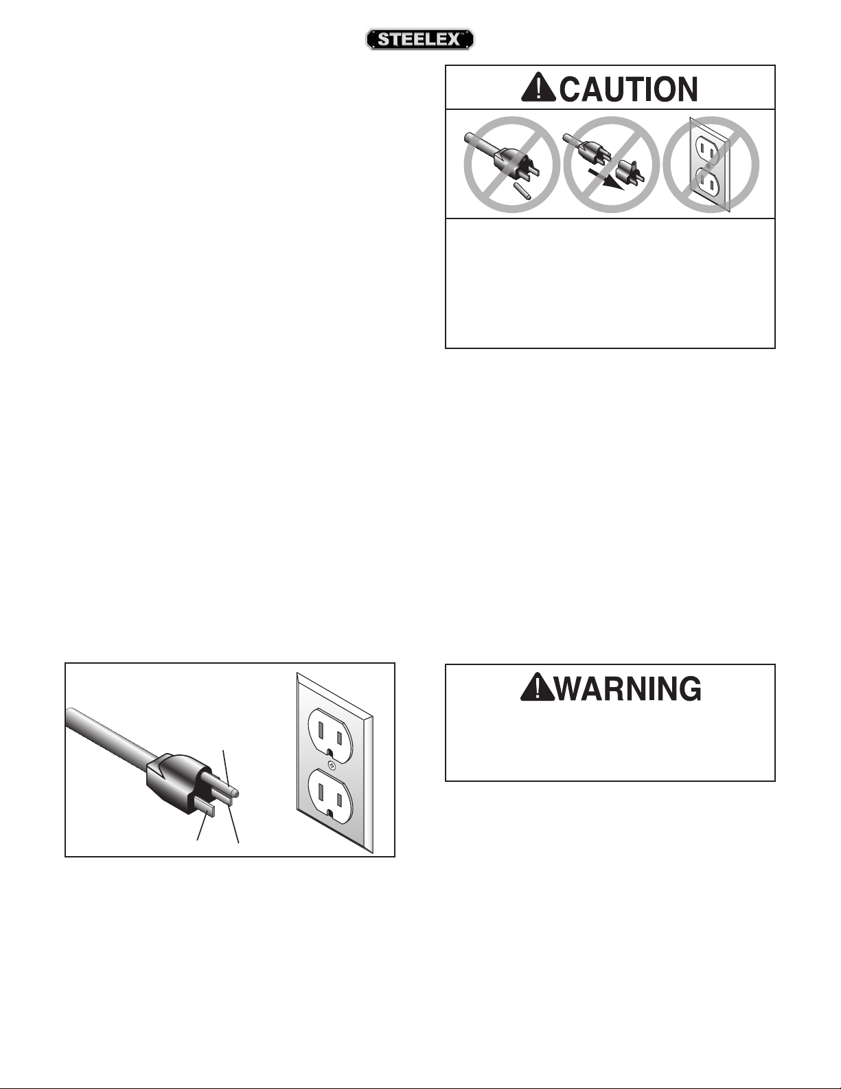
For 120V Connection
This machine is equipped with a power cord that
has an equipment-grounding wire and NEMA 5-15
grounding plug. The plug must only be inserted into
a matching receptacle (see Figure 5) that is properly
installed and grounded in accordance with local
codes and ordinances.
Grounding Prong
Neutral Hot
5-15 PLUG
GROUNDED
5-15 RECEPTACLE
Figure 5. NEMA 5-15 plug & receptacle.
Extension Cords
Minimum Gauge Size at 120V .................. 14 AWG
Maximum Length (Shorter is Better) ............50 ft.
We do not recommend using an extension cord
with this machine. Extension cords cause voltage
drop, which may damage electrical components and
shorten motor life. Voltage drop increases with lon-
ger extension cords and smaller gauge sizes (higher
gauge numbers indicate smaller sizes).
Any extension cord used with this machine must
contain a ground wire, match the required plug and
receptacle, and meet the following requirements:
The machine must be properly set up before
it is safe to operate. DO NOT connect this
machine to the power source until instructed
to do later in this manual.
No adapter should be used with the required
plug. If the plug does not fit the available
receptacle or the machine must be reconnected
for use on a different type of circuit, the
reconnection must be made by an electrician
or qualified service personnel and comply with
all local codes and ordinances.
DO NOT modify the provided plug or
use an adapter if the plug will not
fit the receptacle. Instead, have an
electrician install the proper receptacle
on a power supply circuit that meets
the requirements for this machine.

-12- ST1008 Mini Wood Lathe
SETUP
The following is a description of the main components
shipped with the STEELEX™ Model ST1008. Lay the
components out to inventory them.
Note: Some parts and hardware may already be
installed on the machine. Check the machine when you
use this inventory list.
Box Inventory (Figure 6) Qty
A. Mini Wood Lathe (Not Shown) .............................. 1
B. Safety Glasses............................................................... 1
C. Live Center .................................................................... 1
D. Spur Center ................................................................... 1
E. Faceplate 3"................................................................... 1
F. Tool Rest......................................................................... 1
G. Knock Out Bar .............................................................. 1
H. Tool Rest Lock Handles............................................. 2
Inventory
Figure 6. Box inventory.
B
C
D
E
F
G
H
This machine presents
serious injury hazards
to untrained users. Read
through this entire manu-
al to become familiar with
the controls and opera-
tions before starting the
machine!
The Model ST1008 was carefully packed when it
left our warehouse. If you discover the machine is
damaged after you have signed for delivery, please
immediately call Customer Service at (360) 734-3482
for advice.
Save the containers and all packing materials for pos-
sible inspection by the carrier or its agent. Otherwise,
filing a freight claim can be difficult.
When you are completely satisfied with the condi-
tion of your shipment, you should inventory the
contents.
Unpacking
SUFFOCATION HAZARD!
Immediately discard all plas-
tic bags and packing materi-
als to eliminate choking/suf-
focation hazards for children
and animals.
UNPLUG-power cord before
you do any assembly or
adjustment tasks! Otherwise,
serious personal injury to
you or others may occur!.

ST1008 Mini Wood Lathe -13-
Figure 7. Minimum working clearances.
35½"
15"
120V
6A
Workbench Load
The Model ST1008 weighs 89 lbs. and has a base
footprint of 33" W x 83⁄4" D.
Working Clearances
Consider existing and anticipated needs, size of
material to be processed through each machine,
and space for auxiliary stands, work tables, or other
machinery when establishing a location for your
lathe.
Many of the solvents
commonly used to clean
machinery can be toxic
when inhaled or ingested.
Lack of ventilation while
using these solvents could
cause serious personal
health risks or fire. Take
precautions from this haz-
ard by only using cleaning
solvents in a well ventilat-
ed area.
Site ConsiderationsCleanup
The unpainted surfaces are coated with a waxy oil
to protect them from corrosion during shipment.
Remove this protective coating with a solvent clean-
er or citrus-based degreaser.
To clean thoroughly, some parts may need to be
removed. For optimum performance from your
machine, make sure you clean all moving parts or
sliding contact surfaces that are coated.
Avoid chlorine-based solvents as they may dam-
age painted surfaces should they come in contact.
Always follow the manufacturer’s instructions when
using any type of cleaning product.
Gasoline and petroleum
products have low flash
points and could cause an
explosion or fire if used
to clean machinery. DO
NOT use gasoline or petro-
leum products to clean the
machinery.
The model ST1008 is a
heavy machine. DO NOT
over-exert yourself while
unpacking or moving your
machine—get assistance.
MAKE your shop “child
safe.” Ensure that your
workplace is inaccessible to
youngsters by closing and
locking all entrances when
you are away. NEVER allow
untrained visitors in your
shop when assembling,
adjusting or operating
equipment.
Lighting
Lighting should be bright enough to eliminate shad-
ow and prevent eye strain.
Electrical
Electrical circuits must be dedicated or large enough
to handle amperage requirements. Outlets must be
located near each machine, so power or extension
cords are clear of high-traffic areas. Follow local elec-
trical codes for proper installation of new lighting,
outlets, or circuits.

-14- ST1008 Mini Wood Lathe
Assembly
To assemble the lathe:
1. Turn the release lever on the tool rest base so it
does not interfere with assembly.
2. Thread the tool rest lock handles into the tool
rest base (Figure 10) until the threaded ends of
the handles are flush with the inside of the shaft.
Figure 11. Tool rest installed.
Figure 10. Tool rest lock handles installed.
Lock Handles
Release Lever
Tool Rest
Base
3. Insert the tool rest shaft into the base and turn
the handles to lock it as shown in Figure 11.
4. Install the optional bed extension, Model ST1009
(Page 26). Refer to the instruction sheet includ-
ed with the bed extension.
Bench Mounting
Number of Mounting Holes................................. 4
Dia. of Mounting Hardware Needed ...............5⁄16"
The base of this machine has mounting holes that
allow it to be fastened to a workbench or other
mounting surface to prevent it from moving during
operation and causing accidental injury or damage.
The rubber feet on this machine must be removed
before bench mounting.
The strongest mounting option is a "Through Mount"
(see Figure 8) where holes are drilled all the way
through the workbench—and hex bolts, washers,
and hex nuts are used to secure the machine in place.
Figure 9. "Direct Mount" setup.
Machine Base
Workbench
Lag Screw
Flat Washer
Machine Base
Workbench
Hex
Bolt
Flat Washer
Flat Washer
Lock Washer
Hex Nut
Figure 8. "Through Mount" setup.
Another option is a "Direct Mount" (see Figure 9)
where the machine is secured directly to the work-
bench with lag screws and washers.

ST1008 Mini Wood Lathe -15-
Test Run 4. Remove switch disabling key, as shown in Figure
12.
DO NOT start machine until all preceding setup
instructions have been performed. Operating
an improperly set up machine may result in
malfunction or unexpected results that can
lead to serious injury, death, or machine/prop-
erty damage.
Serious injury or death can result from
using this machine BEFORE understanding
its controls and related safety information.
DO NOT operate, or allow others to operate,
machine until the information is understood.
To test run the machine:
1. Clear all setup tools away from machine.
2. Connect machine to power supply.
3. Turn machine ON, verify motor operation, and
then turn machine OFF.
The motor should run smoothly and without
unusual problems or noises.
5. Try to start machine with paddle switch. The
machine should not start.
— If the machine does not start, the switch dis-
abling feature is working as designed.
— If the machine does start, immediately stop
the machine. The switch disabling feature
is not working correctly. This safety feature
must work properly before proceeding with
regular operations. Call Tech Support for
help.
Figure 12. Removing switch key from paddle
switch.
Once assembly is complete, test run the machine to
ensure it is properly connected to power and safety
components are functioning correctly.
If you find an unusual problem during the test run,
immediately stop the machine, disconnect it from
power, and fix the problem BEFORE operating the
machine again. The Troubleshooting table in the
SERVICE section of this manual can help.

-16- ST1008 Mini Wood Lathe
OPERATIONS
Loose hair/clothing could
get caught in machinery
and cause serious person-
al injury. Keep clothing and
long hair away from moving
machinery.
Eye injuries or respiratory problems can occur
while operating this tool. Wear personal pro-
tective equipment to reduce your risk from
these hazards.
NOTICE
If you have never used this type of machine
or equipment before, WE STRONGLY RECOM
MEND that you read books, trade magazines,
or get formal training before beginning any
projects.
The Model ST1008will perform many types of opera-
tions that are beyond the scope of this manual. Many
of these operations can be dangerous or deadly if
performed incorrectly.
The instructions in this section are written with the
understanding that the operator has the necessary
knowledge and skills to operate this machine. If at
any time you are experiencing difficulties performing
any operation, stop using the machine!
If you are an inexperienced operator, we strongly
recommend that you read books, trade articles, or
seek training from an experienced jointer operator
before performing any unfamiliar operations. Above
all, your safety should come first!
Overview
To complete typical operation, operator does the
following:
1. Examines workpiece to make sure it is suitable
for turning. No extreme bows, knots, or cracks
should exist.
2. Prepares and trims workpiece to make it roughly
concentric.
3. Installs workpiece between centers, or attaches
it to faceplate or chuck.
4. Adjusts tool rest to 1⁄8" above workpiece center-
line, and sets minimum clearance between the
workpiece and lip of tool rest to 1⁄4".
5. Rotates workpiece by hand to verify that the
spindle and workpiece rotate freely throughout
the range of motion.
6. Positions dust collection hood near work piece
to collect wood chips secure in place.
7. Ties back loose hair and clothing, and puts
on face shield and respirator. Takes all other
required safety precautions.
DO NOT investigate prob-
lems or adjust the lathe
while it is running. Wait
until the machine is turned
OFF, unplugged and all
working parts have come
to a complete stop before
proceeding!

ST1008 Mini Wood Lathe -17-
Stock Inspection &
Requirements
Some workpieces are not safe to turn or may require
modification before they are safe to turn. Before
turning a workpiece, inspect all workpieces for
the following:
Workpiece Type: This machine is intended for cut-
ting natural and man-made wood products, and
some plastics. Never attempt to cut any metal, stone,
or rubber workpiece; cutting these materials can lead
to machine damage or severe injury.
Foreign Objects: Nails, staples, dirt, rocks and other
foreign objects are often embedded in wood. While
cutting, these objects can become dislodged and
hit the operator, cause tool grab, or break the turn-
ing tool, which might then fly apart. Always visually
inspect your workpiece for these items. If they can't
be removed, DO NOT turn the workpiece.
Large/Loose Knots: Loose knots can become dis-
lodged during the turning operation. Large knots can
cause a workpiece to completely break in half during
turning and cause machine damage and personal
injury. Choose workpieces that do not have large/
loose knots.
Excessive Warping or Twists:Workpieces with
excessive bowing or twisting are unstable and unbal-
anced. Never turn these workpieces at high speed,
or instability will be magnified and the workpiece
can be ejected from the lathe causing impact injures.
Only turn concentric workpieces!
Disabling Switch
Figure 13. Disabling switch by removing key.
The switch can be disabled by removing the key, as
shown below. Disabling the switch in this manner
can prevent unauthorized operation of the machine,
which is important if it is not kept inside an access-
restricted building or in a location where children
may be present.
IMPORTANT: Disabling the switch only restricts its
function. It is not a substitute for disconnecting
machine from power when adjusting or servicing.
Children or untrained people can be seriously
injured by this machine
. This risk increases
with unsupervised operation.
To help prevent
unsupervised operation, always disable switch
before leaving machine unattended. Make sure
to place key in a well-hidden or secure location!

-18- ST1008 Mini Wood Lathe
BELT 60 Hz
A 480
1270
1960
2730
3327
4023
B
D
E
F
C
A
B
C
DE
Motor Pulley
Spindle Pulley
F
Figure 15. ST1008 Speed Chart.
For Example: As indicated in the speed chart,
belt position B creates 1270 RPM (see Figure 15).
5. Move the belt tension lever down, tighten the
lock knob, and reinstall the access plate and
spindle cover.
Note: When properly tensioned, the belt should
deflect about 3⁄8" when moderate pressure is
applied to the belt mid-way between upper and
lower pulleys, as shown in Figure 16.
Pulley
3⁄8"
Deflection
Pulley
Figure 16. Proper belt deflection.
3. Loosen the belt tension lock knob, and move
the belt tension lever up to reduce tension on
the belt.
4. Locate the desired speed on the speed chart
on the spindle cover, and move the belt to the
desired grooves on the motor and spindle pul-
leys.
Figure 14. Belt Access.
Lock Handle
Access Plate
Belt Tension
Lock Knob Belt Tension Lever
Spindle
Cover
To change speeds, the belt in the headstock must be
repositioned. A chart on the spindle cover shows the
belt positions needed to make the lathe run at the
desired speed.
To change speeds:
1. DISCONNECT MACHINE FROM POWER!
2. Loosen the lock handle, remove the spindle
cover, and open the access plate (Figure 14).
Changing Spindle
Speeds
Table of contents
Other Steelex Lathe manuals


