Micromark MicroLux 85181 User manual

6” x 10”*Variable Speed
Micro Lathe
Instruction Manual
Made in China for
340 Snyder Avenue
Berkeley Heights, NJ 07922
For technical assistance, call 908-464-1094 Monday thru Friday, 1pm to 5pm ET
©Micro-Mark
MM120711
Please read and understand all instructions before using this tool.
Note: These instructions will show you how to assemble this machine,
work its controls and maintain it for long life.
It is not intended as an educational course on how to make parts using a lathe.
#85181
*Nominal size

Specifications
Feature and Legend
1. The Headstock
2. The Running Gear
3. The Tailstock
4. The Saddle and the Cross-Slide
Unpacking and Preparing for Use
Starting Procedure
Operation
Maintenance
Settingsand Adjustments
Accessories
Parts List
Parts Diagram
Wiring Diagram
Packing List
CONTENTS
Important Safety Instruction
2

1. When using electric tools, machines or equipment, basic safety precautions should
always be followed to reduce the risk of fire, electric shock, and personal injury.
2. Keep work area clean. Cluttered areas invite injuries.
3. Consider work area conditions. Do not use machines or power tools in damp, wet, or
poorly lit locations, Do not expose equipment to rain. eep work area well lit. Do not use
tools in the presence of flammable gases or liquids.
4. Keep children away from the work area.
5. Guard against electric shock.Prevent body contact with grounded surfaces such as
pipes, radiators and ranges.
6. Stay alert. Never operate if youare tired.
7. Do not operate the product if under the influence of alcohol or drugs. Read warning
labels on prescriptions to determine if your judgment or reflexes might be impaired.
8. Do not wear loose clothing or jewelry as they can be caught in moving parts.
9. Wear restrictive hair covering to contain long hair.
10. Wear eye and ear protection.
11. Keep proper footing and balance at all times.
12. Do not reach over or across running machines.
Before operations
1. Be sure the switch is OFF when not in use and before plugging tool into power outlet.
2. Do not attempt to use inappropriate attachments in an attempt to exceed the tool's
capacity. Approved accessories are available from Micro-Mark.
3. Check for damaged parts before using any tool. Any part that appears damaged
should be carefully checked to determine that it will operate properly and perform its
intended function.
4. Check for alignment and binding of all moving parts, broken parts,mounting fixtures,
and any other condition that may affect proper operation. Any part that is damaged
should be properly repaired or replaced by a qualified technician.
5. Do not use the tool if any switch does not operate properly.
Operation
1. Never force the tool or attachment to do the work of a larger industrial tool. lt is designed
to do the job better and more safely at the rate for which it was intended.
2. Do not carry the tool by its power cord.
3. Always unplug the cord by the plug. Never yank the cord out of the wall.
4. Always turn off the machine before unplugging.
IF THERE IS ANY QUESTION ABOUT A CONDITION BEING SAFE OR UNSAFE,
DO NOT OPERATE THE TOOL!
Grounding Instructions
This machine has a three prong plug -- the third prong is the ground. Plug this cord into a
three-prong receptacle only. Do not attempt to defeat the protection the ground wire provides by
cutting off the round prong. Cutting off the ground will result in a safety hazard and void the
warranty.
DO NOT MODIFY THE PLUG IN ANY WAY. IF YOU HAVE ANY DOUBT, CALL A
QUALIFIED ELECTRICIAN.
3
IMPORATANT SAFETY INSTRUCTIONS
READ ALL INSTRUCTIONS AND WARNINGS BEFORE USING THIS TOOL
Operator
PLEASE REMEMBER:

1. Clutch (for changing manual & auto feeding) 2. Forward / Off / Reverse Switch
3. Emergency Stop Switch 4. Changing gear box cover
5. Variable Speed Control Knob 6. Chuck and Chuck Cover
7. DC Motor 8. Rear Splash Guard
9. Tool Rest 10. SaddIe and Cross Slide
11. Tailstock Quill Lock Handle 12. Tailstock Casting
13. Leadscrew and Handwheel 14. Bed Way
15. Apron 16. Fuse Box
17. Power Indicator Lamp (Green) 18. Reset Indicator Lamp (Yellow)
SPECIFCATIONS
Max. swing over bed 140 mm (51/2" )
Max. Iength of workpiece 250 mm (10")
Spindle hole taper MT2
Cross slide travel 60 mm (23/8" )
Hole of spindle 9 mm (3/8")
Tailstock taper MT1
Spindle speed (Variable speed) 100 - 2000rpm ±10%
Screw threads Imperial 16, 18, 19, 20, 24
Motor output power 150W
Net/Gross weight 22 / 26 kgs.
FEATURES
LEGEND
4
13 15 14
2
4
13
1211
10
9
8
6
7
5
181716

1. THE HEADSTOCK
5
2. THE RUNNING GEAR
3. THE TAILSTOCK
4. THE SADDLE AND THE CROSS-SLIDE
UNPACKING & PREPARING FOR USE
With assistance, considering the weight of machine, oe t to a good solid surface or
workbench. Proceed to remove all traces of preservative with paraffin or good quality solvent,
and lightly oil all machined surfaces.
Saddle, cross-slide and compound slide adjustments are all factory set to ensure smooth
movement in both directions. lf,however,the adjustments have been upset during transit,
indicated by stiff or erratic movement, refer to settings and adjustments for the methods of
adjustment.
All hex keys and spanners necessary to carry out various adjustments are supplied, together
with a chuck key for the 3-jaw chuck and a spare fuse. The fuse holder is located on the main
control panel.
The three external jawfor the 3-jaw self centering chuck can extend the capacity of the chuck.
The motor provides direct drive to the spindle via an internal tooth-type belt. Spindle speed is
variable, and is regulated by the Speed Control Knob (5). Located on the main control panel.
The spindle is provided with an internal No. 2 Morse taper to accommodate a center for use
with a face plate or turning clamp.
The 3-jaw Self Centering Chuck (6) is mounted on the spindle flange. To remove the chuck,
simply remove the three securing nuts to rear of the flange allowing it to be pulled free together
with three mounting studs.
Note: The Chuck has a protection cover (6). Opening the cover causes main power of the
lathe to be switched off. Keep the cover closed to operate.
The Running Gear, ls protected by a cover (4), open the cover (4) of the gear box on the left side of
the machine, and select the gear (see 'Accessories') of the correct size according to the desired
feeding rate or pitch size. lnstall the appropriate gear into the gearbox and connect it to the
leadscrew. (Refer to the 'changing gear'label on the machine.)
Automatic feeding is enabled or disabled by control the clutch (1) on the main panel. Turn the
Clutch Handle (1) to the left (a hand ) for manual feeding. Turn the Clutch Handle (1) to the right (a
screw) for automatic feeding.
The Tailstock Casting (12), may be moved along the bed to any desired position and is secured in
position by two screw(ront of the tailstock) w lock or loosenthe wedge of the tailstock.
The tailstock spindle carries an internal No. 1 Morse taper for use with the Center provided.
The saddle carries the Cross-Slide (10), onto which is mounted the Tool Rest (9) allowing intricate
and delicate operations to be performed. lt may be driven by a leadscrew, ia a Drive Nut, to
provide automatic feed when the Clutch (1),at the right position, is operated.
On receipt, carefully unpack the lathe, inspect to ensure that no damage was suffered in transit
and all parts are accounted for. Should any damage be apparent, or parts are missing, please
contact your dealer immediately and ae a iin caron or e carrier' inecion.

MOUNTING THE MACHINE
STARTING PROCEDURE
A. DURING INSTALLATION - INITIAL START
The machine should be mounted on a workbench of
sufficient height so that you do not need to bend your
back to perform normal operations.
Ensure the location is adequately lit and that you will
not be working in your own shadow.
We strongly recommend that the machine e bolted
firmly to a workbench, using the tapped holes to
secure the feet to the machine. This is to provide
added stability and, consequently, additional safety.
To do this, first drill three M6 clearance holes in a
worktop, at the dimensions shown in the diagram
opposite, and with appropriate length M6 bolts, or
screws, with flat washers (not supplied).
Tak ing all precautions previously stated, ensure tat the cross-slide is well away from the chuck,
and the clutch for manual and auto feeding is in te left position. Close the chuck' protectie
cover. Insert the electric plug into te socket.
o ar e ae ir reeae e erency o ic A.
en eec orard or eere a deired .
inay roae e eed conro o e deired eed.
Run te ane or a total 5 minutes, gradually
increasn spindle speed to its maximum. Run for at
least 2 minutes at this speed before stopping the
machine and disconnecting from the
main supply.
Check that all components are still secure and working freely and correctly.
Check also to ensure the mountings are secure.
CAUION:
ALWAYS turn the machine OFF i e ariae eed Sic and e orard eere
Swic aein o change any settings or make any adjustments.
6
B A
420mm
85mm

B. STARTING UNDER NORMAL CONDITIONS
1. Take all necessary precautions previously stated, and ensure the workpiece can rotate fully without obstruction.
2. Put the manual & auto feeding Clutch to right or left side, depending upon whether or not auto feeding is required.
IMPORTANT: This should ALWAYS be a deliberate, conscious action.
3. To prevent damage, the carriage drive screw clutch must be engaged with the motor off. To engage the clutch,
turn the clutch control knob (1) gently clockwise while, at the same time, rotating the lead screw hand wheel (13)
until the clutch fully engages (you’ll feel this in the knob as it goes all the way “over”). Before starting the lathe,
you’ll want to make sure there is plenty of clearance for the carriage to move unobstructed. The carriage drive
may be disengaged while the lathe is either running or stopped. To do so, rotate the control knob with a swift, firm
motion counterclockwise to the disengaged position. Remember to stop the lathe before attempting to re-engage
the carriage drive screw clutch.
4. Proceed to start the machine as described in Section A.
5. If the machine is finished with or is to be left unattended, turn the F/O/R switch to the OFF position then
disconnect from the main supply.
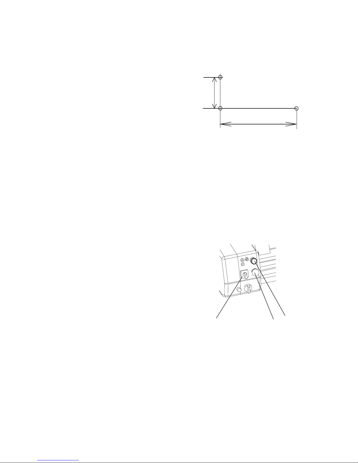
ATTENTION: The power supply system of this machine has an automatic overload protective device. If cutting or
drilling too deep, the system will stop working, and a yellow lamp (C, on the main panel) will light. Just turn down the
Variable Speed control knob (E) and move directional switch (A) to neutral and then turn on again. The system will
work again and the yellow lamp will go off automatically.
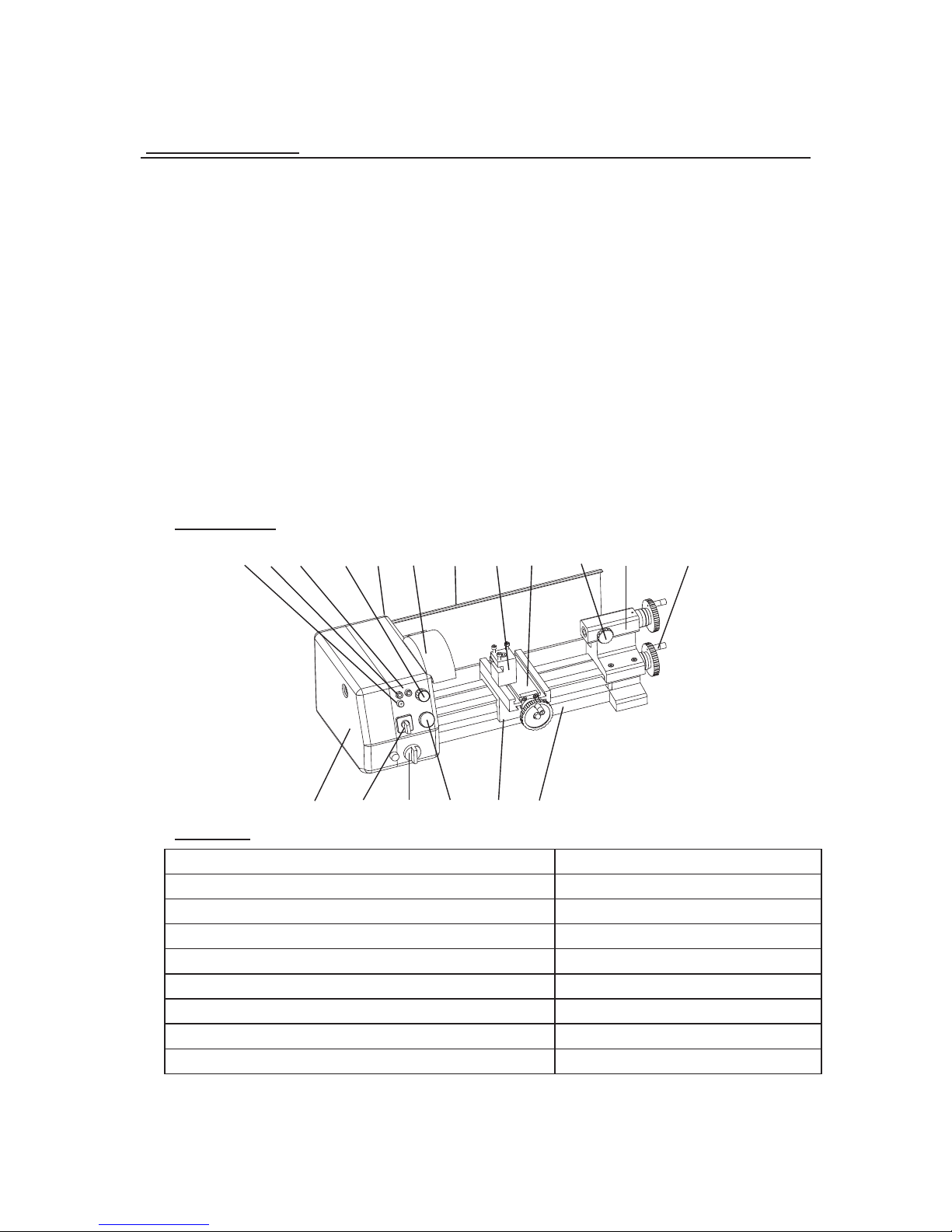
OPERATION
SIMPLE TURNING
Before starting the machine, as described above, it is imperative that the setup for the type of work to be carried out
is fully checked.
The following notes are guidelines as to how to set up the lathe in order to carry out a simple turning operation.
ALWAYS plan your work. Have drawings or a plan on hand together with any measuring instruments you may
require, such as micrometers / verniers / calipers etc.
Select a cutting tool that will produce the desired cut and mount in the tool rest, with as little overhang as possible,
secure it using the hex socket head screws (ideally, the overhang should be approximately 6mm but not more than
8mm for a straight tool).
lt is IMPORTANT to ensure that the tip of the cutting tool is on the center line of the work, or very slightly below it.
On no account should it be above the center line.
Where necessary, shims should be used beneath the tool in order to achieve the correct height or, if the tip is too high
or too low, you may find the rocker side useful, and the last recourse is to select another tool or grind down the tip.
To ch e ck th e tip i s at th e c or r ect h eig ht, p o si t ion t he to ol so t h at t h e tip i s alm ost t ouc h ing t he po int o f the t a ils toc k
center. They should coincide. If necessary make adjustments using shims or grind down the cutting tip or select
another tool.
When satisfied, mount the work, either in the chuck or on a faceplate, and if necessary, use the tailstock center
for additional support(if the work cannot be adequately secured by the chuck, or if it is a long piece, or of small
diameter). Additionally, ‘Steady rest’may be used.
If the tailstock is not to be used you may remove it completely by slackening off the securing screws at its base, and
sliding it free of the bed.
Mark the surface of the work at the point where the cut is to end, i.e. the shoulder, using a scriber or similar means,
and move the saddle so that the cutting tool is directly opposite the mark, then wind in the cross-slide so that the tool
touches the surface of the work.
While carrying out these maneuvers, rotate the chuck by hand to ensure that nothing will come into contact with it
when turning takes place, i.e. there is adequate clearance between the saddle, cross-slide, tool post or cutting tool,
and the chuck.
7

When satisfied,retract the cutting tool and wind the saddle away from the headstock, then wind
the cutting tool up to the work somewhere along the length to be cutwhilerotating the work
by hand using the chuck.
Continue to advance the cutting tool slowly,
until it just touches the surface. Record this
position by zeroing the scale on the cross-
slide, i.e. turn the moveable scale until the
tool is a short distance from the right hand
edge of the wor. n in the cross-slide
again one full turn until the zero marks again
coincide.
lMPORTANT: lf you go past the zero marks,
back off again at least one half of a turn, then slowly bring the marks back together.
Whenever you use the scale as an indicator to advance the cross-slide or compound slide,
ALWAYS use this procedure to alignthe marks. This is to take into account backlash and
other clearances in the gearing and slides,etc.
Continue to turn the handle an amount equivalent to your desired depth of cut.
NOTE: We recommend that for rough cutting, you do not exceed 0.010" (0.25mm) as
8
The setup is now complete to begin your cutting operationbut before starting, check the
position of the Clutch for changing the manual & auto feeding set to left poton.
Switch the machine ON as described under Starting Procedure and slowly feed the cutting
tool into the work using the manual feed handle. Proceed until you reach the previously marked
line on the work, then retract the tool one or two complete turns on te ross-slide feed handle.
Wind the saddle back to the beginning,then wind the tool the same number of turns in, plus
the depth of desired cut, and proceed to cut once more.
NOTE: this describes the procedure for general, rough cutting. For other types of cuts, finishing,
cutting shoulders etc., you should consult a suitable handbook.
IMPORTANT:Your left hand should always be free in order to hit the emergency stop
should it become necessary.
MAINTENANCE
For maximum performance, it is essential that the lathe is properly maintained.
BEFORE USE
Always inspect before use. Any damage should be repaired and maladjustments rectified.
Damage to machined surfaces should be repaired with an oil stone. Test by hand to ensure
smooth operation of all parts before use.
lnject a few drops of oil nto the oilways at both leadscrew bearing(each end bracketonce or twice
during the day if used continuously. lt will be necessary to remove the geartrain cover in order to
oil the left hand bearing.
lo nject a few drops nto the compound slide oilway, located on the slide top surface, between
the two hex socket head screws.
AFTER USE
Remove all er from the machine and thoroughly clean all surfaces. lf coolant has been used,
ensure it has completely drained from the tray.
Components should be dry, and all machined surfaces should be lightly oiled.
Always remove cutting tools, and store in a safe place.
MOTOR BRUSHES
The motor brushes may be changed by unscrewing the caps, at the upper en of the motor, beneath
the headstock.
your depth of cut.
05
10 45 40

Occasionally, it may be necessary to readjust various components in order to maintain optimum
performance. The adjustments that may be performed are as follows:
The cross-slide is mounted on a dovetail slide, as shown below. Between the sloping surfaces on
one side of the dovetail, a ib strip is inserted, which may be tightened against the dovetail under
the influence of three adjuster, or ib screws,mounted along it lent.
The ib screws are to be found on the right hand side of the slide, directly beneath the compound
slide handle. ln time, wear will occur on the mating surfaces resulting in a sloppiness of action.
To adjust the ib strip, account for wear,and ensure the slide moves evenly and smoothly,
proceed as follows:
1. Looen all lock nuts and screw in the
ib screws evenly, i.e. use the same torque
for each screw. The slide should be held
firmly. Test by trying to turn the handle, but
do not force it.
2. Screw out each ib screw by one quarter of
a turn only, and nu up the lock nuts.
3. Test again, by turning the handlethe
movement should be even and smooth
along its complete length.
4. lf the movement is too slack, screw all adjusters in by one eighth of a turn, and re-try.
Similarly, if the movement is too stiff, screw out the adjusters by one eighth of a turn until the
correct adjustment is attained.
5. Tighten all lock nuts,taking care to ensure you do not move the ib screws whiledoing so.
6. When completed, retract the slide fully and apply oil to all mating surfaces and the feed screw
thread, then wind the slideback to its normal position.
The cross-slide feed should run smoothly, and the scale must rotate with the handle.
lf any stiffness occurs, it is probably the result of er lodging between the mating surfaces.
Undo the screw securing the handwheel. Remove the handwheel and pull off the collar
with the scale,taking great are to retan te all prn plate w t n a rooe
beneath the collar.
Clean the assembly and reassemble n reverse order. ltwill be necessary to hold the spring plate
in place with a small screwdriver, or similar tool, wle pushing down on it to allow the collar to be
correctly located on to the shaft.
The tailstock loe by two screw. en te rew are loosene, the tailstock can moved left or rt.
en locke own, te talto can e fixed any position alon the bed way.
SETTINGS AND ADJUSTMENTS
A. CROSS-SLIDE ADJUSTMENTS
B. CROSS-SLIDE FEED HANDLE
C. TAILSTOCK ADJUSTMENTS
NOTE:
lt is important that the cross-slide and compound slide adjustments are ae correctly and that
there is no sloppiness of action. Any maladjustment will have a serious effect on the quality of
your work, as they will all be transferred to the tool tip. lt is vital that there is as little movement of
the tool as possible.
9
ib strip
ib or
Adjuster
Screws

ACCESSORIES
cessories for your machine are aalale ro ro-ar:
10
OPTIONAL AC CE SS OR IE S


Part List(1)
Item
Description
Description
Description
Description
Q'ty
Item
Description
Description
Description
Description
Q'ty
1
Change gear cover
1
54
Screw base
1
2
Cap Screw GB818, M4*8
9
55
Key 2*10
3
3
Cap Screw GB818, M4*12
6
56
Tailstock screw
1
4
Hinge L*B=38*31
2
57
Screw M5*8
1
5
Washer 4
4
58
Screw M5*20
6
6
Nut M4
4
60
Wedge
1
7
Cantilever
1
61
Lock handle
1
8
Nut M6
2
62
Tailstock quill
1
9
Washer 6
7
63
Dial
1
10
Compression spring
1
64
Screw M5*14
4
11
Spacing ring
1
65
Screw bracket
1
12
Cover for Spindle box
1
66
Bed lead rail
1
13
Rotate spindle
1
67
leadscrew
1
14
Key 3*6
1
68
Steel ball 5
1
15
Protect cover for chuck
1
69
Compression spring
1
16
Cap screw M4*8
2
70
Screw M6*10
4
17
Cap screw M5*8
3
71
Pin 3*14
1
18
Rear splash guard
1
72
Clutch bracket
1
19
Motor
1
73
Clutch
1
20
Key 3*16
1
74
Key 3*22
1
21
Check ring 8
2
75
Shaft
1
22
Timing pulley
1
76
Key 3*14
1
23
Support plate
1
77
Gear shaft bracket
1
24
Screw M4*10
5
78
Nut M5
2
26
Spring washer 6
2
79
Support plate
1
27
Screw M6*20
2
80
Washer
3
28
Washer 8
6
81
Change gear Z=72
1
29
Spring washer 8
6
82
Change gear Z=19
1
30
Screw M8*20
2
83
Change gear Z=76
1
31
Small round nut M18*1.5
2
84
Change gear Z=24
1
32
Spindle gear 36T
1
85
Gear sleeve
2
33
Spacing ring (I)
1
86
Gear shaft
2
34
Spindle timing pulley
1
87
Screw M5*8
2
35
Spacing ring (II)
1
88
Spacing ring
1
36
Behind oil seal(ring)
1
89
Change gear Z=90
1
37
Bearing 30205
2
90
Screw M5*25
1
38
Spindle box
1
91
Bed base
1
39
Front oil seal(ring)
1
92
Screw M6*35
4
40
Key 6*36
1
93
Unplug shaft
1
41
Spindle
1
94
Retaining plate
1
42
Key
1
96
Clutch rotate knob
1
43
Nut M6
3
97
Retaining plate
1
44
Screw M6*25
3
98
Leadscrew bracket
1
45
Chuck flange
1
99
Cross slide screw
1
46
Round cap screw M4*12
11
100
Saddle
1
47
80mm 3
-
jaw chuck
1
101
Cross slide nut
1
48
Handle screw
3
102
Leadscrew nut
1
49
Rotate small handle
3
103
Cross slide
1
50
Handwheel
3
104
Screw M4*16
7
51
Cap nut M6
3
105
Nut M4
7
52
Screw M8*12
4
106
Cross slide wedge
1
53
Space ring
1
107
12
Gib strip
1

Part List(2)
Item
Description
Description
Description
Description
Q'ty
Item
Description
Description
Description
Description
Q'ty
108
Screw M8*40
2
130
Screw M5*20
4
109
Tool rest
1
131
Timing belt 1.5*83*10
1
110
Tool rest shaft
1
132
Yellow lamp
1
111
Connect block
1
143
Screw M4*6
1
112
Potentiometer
1
148
Screw M4*6
3
113
Emergency stop switch
1
153
Tool rest block
1
114
Forward/off/Reverse switch
1
194
Spring
3
115
Power indicator light
2
195
Dial
1
116
Fuse box
1
218
Big washer
1
117
pc board
1
219
Washer
1
118
Lock connect
1
220
Tailstock casting
1
119
PC board box
1
221
Base plate
1
120
Screw ST2.9*9.5
4
223
Screw M6*20
1
121
Micro switch
1
224
Bearing sleeve
1
122
Screw ST2.2*9.5
2
250
Screw M8*35
1
123
Power line
1
252
Spacing ring
1
125
Switch label
1
253
Screw M8*25
4
126
Change gear label
1
254
13
Screw M3*8
2
127
Main label
1
128
Scale label (I)
2
129
Scale label (II)
1

Wiring Diagram I (220-240/50Hz)
see the label
14

Wiring Diagram II(100-120V/60Hz)
See the label
15

No.
1
2
3
4
5
6
7
8
9
10
11
Packing List
Qty.Remarks
1
Each 1
1
1
1
1
1
2
1
3
1
Descriptions
Micro Lathe
L Hex.Wrench S:2,3,4,6
Double end wrench 5.5*7
Socket head Wrench 28~32
Center MT#1
Oil cup
Fuse
T-nut
Key for chuck
External jaws
lnstruction Manual
Micro-Mark guarantees this product to be free of manufacturing defects for a period of 90
days from date of shipment, regardless of the amount of time the product has been used
and/or stored. The product, or parts thereof, will be repaired or replaced (at our option) and
shipped back to you free of charge if the following conditions have been met:
• the product is shipped back to us within the warranty period,
• incoming transportation charges have been pre-paid,
• proof of purchase has been provided, and
• our Service Department determines that the problem was caused by a defect in material
and/or workmanship.
Please return to at the address below with a note
explaining the problem.
For products returned after the warranty period, our regular repair charges shall apply. Please
include your telephone number so we may advise you of the repair estimate. Any product
returned to the purchaser without repair work being performed shall be shipped C.O.D. for
the return transportation charges.
This warranty does not cover damages resulting from improper assembly, adjustment or
maintenance, accident, alterations, normal wear, abuse or misuse, and does not apply where
products are used commercially. The warranty shall also not apply when the product has been
used for purposes beyond those for which it was designed or unreasonable for its size.
Micro-Mark makes no other warranty of any kind whatever, expressed or implied, and all implied warranties of merchantability
and fitness for a particular purpose which exceed the above mentioned obligation are hereby disclaimed by Micro-Mark and
excluded from this warranty.
This warranty gives you specific legal rights and you may also have other rights which vary from state to state. The obligation
of the warrantor is solely to repair or replace the products. The warrantor is not liable for any incidental or consequential
damages due to such defect. Some states do not allow the exclusion or limitations of incidental or consequential damages,
so the above limitations or exclusion may not apply to you.
! " #
! " # $ ! % & ' ( ) * + , - -
Table of contents
Other Micromark Lathe manuals