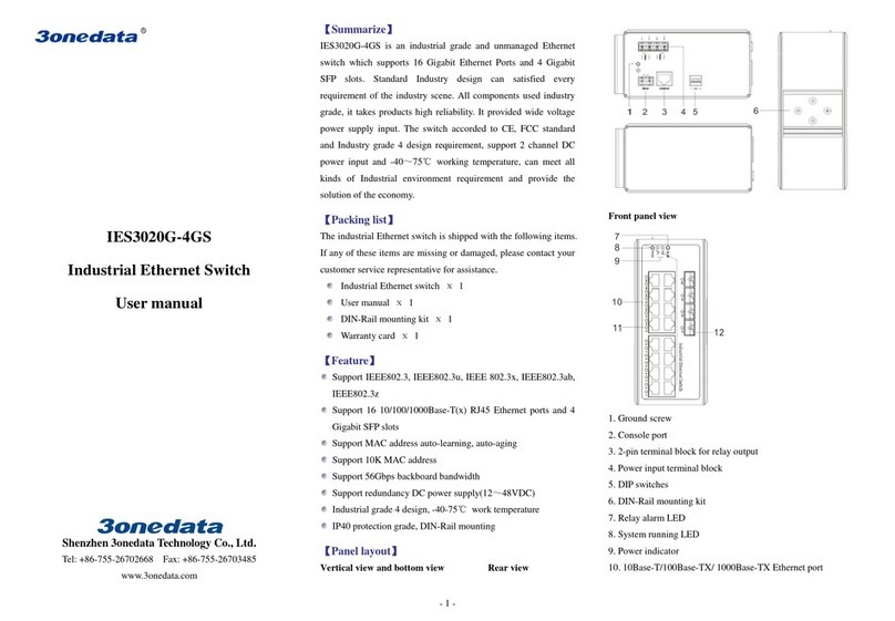
Shenzhen 3onedata Technology IES1024 Series User manual

- 1 -
IES1024 Series
Industrial Ethernet switch
User manual
Shenzhen 3onedata Technology Co. Ltd.
Tel: +86-755-26702668 Fax: +86-755-26703485
www.3onedata.com
Summarize
IES1024 se ies is an indust ial g ade and unmanaged indust ial
Ethe net switch. The indust ial Ethe net switch consists of 24 Fast
Ethe net po ts. Suppo t Fast Ethe net coppe po ts and optical
fibe po t option. The indust ial Ethe net switches p ovide an
economical solution fo you indust ial Ethe net connection. The
switch with a single powe se ies and edundancy powe se ies of
two p oducts can be optional. Dual powe supply p oduct suppo t
edundancy backup function. The single powe supply p oducts
do not suppo t the edundancy function.
The switches have an ope ating tempe atu e ange of -40 to 75°C,
and a e designed with low consumption and without fan. The
ugged ha dwa e design makes the switch pe fect fo ensu ing
that you Ethe net equipment can withstand the igo s of
indust ial applications.
Packing list
The indust ial Ethe net switch is shipped with the following items.
If any of these items a e missing o damaged, please contact you
custome se vice ep esentative fo assistance.
Indust ial Ethe net switch
1
Use manual
1
Wa anty ca d
1
Powe cable
1
Rackmount ea s
2
Feature
High performance network exchange technology
Suppo t IEEE802.3, IEEE802.3u, IEEE 802.3x
Suppo t 8K MAC add ess
Suppo t 12.8Gbps switching fab ic capacity
10/100BaseT(X)(RJ45)
Sto e and Fo wa d switching p ocess type
Plug-and-play, auto MDI/MDI-X connection
Suppo t auto negotiation speed, F/H duplex mode, and auto
send data cont ol
Suppo t MAC add ess lea ning, aging automatic
Suppo t single o edundancy powe supply (100
240VAC/DC)
Reliable Industrial grade design
Indust ial g ade 4 design, -40-75
wo k tempe atu e
No fan deign
IP30 p otection g ade
19 inch ack mounting
Panel layout
Front view
Rear view
1. Resto e facto y settings
2. Console po t
3. Link/ACT LED

- 2 -
4. Systems unning LED
5. The powe LED
6. Relay ala m LED
7. Rackmount ea s
8. Powe input and Relay output te minal block
9. 10/100BaseT(X) (RJ45) po ts
10. 100Base-FX po ts
11. Rea panel connecto LED
Dimension
The se ies of p oducts a e the same size, and the numbe of the
Ethe net inte face is diffe ent. Unit (mm)
Power supply input
The Indust ial Ethe net switches have singe powe and
edundancy powe two kinds of powe input. The singe powe
se ies ea panel p ovides 5 bit wi ing te minal fo
100~240VAC/DC powe ente ed (L/+, GND, N/-) and elay
output (R+, R-).The unmanaged Ethe net switch elay ala m
function is invalid. Te minal diag am is as follows:
The edundancy powe se ies ea panel p ovides two te minal
blocks (5 bits) fo P1 and P2 input. The edundant powe can be
used independently. P1 and P2 can supply powe at the same time,
once eithe of these two powe s fails, anothe powe can acts as
backup automatically to ensu e eliability of the netwo k. Voltage
input ange is 100
240VAC/DC (te minal block defined as P1:
L/+, GND, N/-; P2: L/+, GND, N/- ).
Impo tant notice:
1. Powe ON ope ation: fi st of all, inse t powe cable’s te minal
block into device’s powe po t, then inse t powe supply plug into
powe sou ce
2. Powe OFF ope ation: Fi st off all, unpin powe plug, then
st ike the te minal block, please take ca e of ope ation sequence.
Communication connector
10/100BaseT(X) Ethernet port
The pinout of RJ45 po t display as below, connect by UTP o STP.
The connect distance is no mo e than 100m. 100Mbps is used
120Ω of UTP 5; 10Mbps is used 120Ω of UTP 3, 4, 5.
RJ 45 po t suppo t automatic MDI/MDI-X ope ation. Can connect
the PC, Se ve , Conve te and HUB .Pin 1,2,3,6 Co esponding
connections in MDI. 1→3, 2→6, 3→1, 6→2 a e used as c oss
wi ing in the MDI-X po t of Conve te and HUB.
10Base-T/100Base-TX a e used in MDI/MDI-X, the define of Pin
in the table as below.
NO. MDI signal MDI-X signal
1 TX+ RX+
2 TX- RX-
3 RX+ TX+
6 RX- TX-
4, 5, 7, 8 — —
Note
“TX±”T ansmit Data±
“RX±”Receive Data±
“—”Not Use.
MDI (straight-through cable)
MDI-X (Cross over cable)
MDI/MDI-X auto connection makes switch easy to use fo
custome s without conside ing the type of netwo k cable.
100Base-FX Fiber port
100Base-FX full-duplex SM o MM po t, SC/ST/FC type .The
fibe po t must be used in pai , TX (t ansmit) po t connect emote
switch’s RX ( eceive) po t; RX ( eceive) po t connect emote
1 8

- 3 -
switch’s TX (t ansmit) po t.
The optical fibe connection suppo ts the line to inst uct enhance
the eliability of netwo k effectively.
Suppose: If you make you own cable, we suggest labeling the
two sides of the same line with the same lette (A-to-A and
B-to-B, shown as below, o A1-to-A2 and B1-to-B2).
LED Indicator
LED indicto light on the f ont panel of p oduct, the function of
each LED is desc ibed in the table as below.
System Indication LED
LED State Desc iption
PWR1
ON Powe is being supplied to
powe input PWR1 input
OFF Powe is not being supplied
to powe input PWR1 input
PWR2
ON Powe is being supplied to
powe input PWR2 input
OFF Powe is not being supplied
to powe input PWR2 input
RUN
ON/OFF System is not unning well
Blinking System is unning well
Link/ACT
(1~24)
ON Po t connection is active
Blinking Data t ansmitted
OFF Po t connection is not active
Installation
Befo e installation, confi m that the wo k envi onment meet the
installation equi e, including the powe needs and abundant
space. Whethe it is close to the connection equipment and othe
equipments a e p epa ed o not.
1. Avoid in the sunshine, keep away f om the heat fountainhead o
the a ea whe e in intense EMI.
2. Examine the cables and plugs that installation equi ements.
3. Examine whethe the cables be seemly o not (less than 100m)
acco ding to easonable scheme.
4. Powe : 100-240VAC/DC powe input
5. Envi onment
wo king tempe atu e: -40
75
Sto age Tempe atu e: -40
85
Relative humidity 5%
95%
Rack mount installation
In most of indust ial application, it is convenience to use ack
mount installation, the step of installation is as follows:
1. Check if have ack mount installation tools and components
(The package p ovided pa ts of components)
2. Check installation place st ong o not, have the place to install
the device o not.
3. Put the device into ack, aim at the sc ew hole of device and
ack, fixed it in st ong sc ew. Easy and convenience to
ope ation.
Wiring Requirements
Cable laying need to meet the following equi ements,
1. It is needed to check whethe the type, quantity and
specification of cable match the equi ement befo e cable
laying;
2. It is needed to check the cable is damaged o not, facto y
eco ds and quality assu ance booklet befo e cable laying;
3. The equi ed cable specification, quantity, di ection and
laying position need to match const uction equi ements, and
cable length depends on actual position;
4. All the cable cannot have b eak-down and te minal in the
middle;
5. Cables should be st aight in the hallways and tu ning;
6. Cable should be st aight in the g oove, and cannot beyond the
g oove in case of holding back the inlet and outlet holes.
Cables should be banded and fixed when they a e out of the
g oove;
7. Use cable should be sepa ated f om the powe lines. Cables,
powe lines and g ounding lines cannot be ove lapped and
mixed when they a e in the same g oove oad. When cable is
too long, it cannot hold down othe cable, but st uctu e in the
middle of alignment ack;
8. Pigtail cannot be tied and swe ved as less as possible.
Swe ving adius cannot be too small (small swe ving causes
te ible loss of link). Its banding should be mode ate, not too
tight, and should be sepa ated f om othe cables;
9. It should have co esponding simple signal at both sides of the
cable fo maintaining.
Specification
Technology
Standa d: Suppo t IEEE802.3, IEEE802.3u, IEEE 802.3x
Flow cont ol: IEEE802.3x flow cont ol, back p ess flow cont ol
Exchange attribute
100M fo wa d speed: 148810pps
100M maximum filte speed: 148810pps
T ansmit mode: sto e and fo wa d
Switching fab ic capacity: 12.8Gbps
MAC add ess table: 8K
Memo y: 4Mbit
Interface
Elect ic po t: 10Base-T/100Base-TX auto speed cont ol, Half/full
duplex and MDI/MDI-X auto detect
100M optic fibe po t: 100Base-FX, SC/ST/FC connecto

- 4 -
Console po t: Retain
Ala m po t: Retain
Transfer distance
Twisted cable: 100M
standa d CAT5/CAT5e cable
Multi-mode: 1310nm, 2/5Km
Single-mode: 1310nm, 20/40/60Km
1550nm, 80/100/120Km
Power supply
Input voltage: 100
240VAC
Type of input: 3 bit te minal block
Ove load Cu ent P otection: 1.2A
Suppo t single powe se ies and dual supply se ies of two
p oducts can be optional.
Consumption
IES1024-P (100~240VAC):
Unload consumption: 5.1W
Full load consumption: 9.7W
IES1024-2F- P (100~240VAC):
Unload consumption: 5.5W
Full load consumption: 10.7W
IES1024-4F - P (100~240VAC):
Unload consumption: 6.3W
Full load consumption: 11.2W
IES1024-8F-P (100~240VAC):
Unload consumption: 10.9W
Full load consumption: 14.8W
IES1024-12F-P (100~240VAC):
Unload consumption: 13.0W
Full load consumption: 16.6W
IES1024-16F-P (100~240VAC):
Unload consumption: 13.4W
Full load consumption: 18.6W
IES1024-20F-P (100~240VDC):
Unload consumption: 16.2W
Full load consumption: 18.3W
IES1024-24F-P (100~240VAC):
Unload consumption: 21.4W
Full load consumption: 22.6W
Working environment
Wo king tempe atu e: -40
75
Sto age tempe atu e:-40
85
Relative Humidity: 5%~95% (no condensation)
Mechanical Structure
Shell: IP30 p otect g ade, metal shell
Installation: 19” 1U ack
Size
W×H×D
: 441.6mm×45mm×208.9mm
Industry Standard
EMI: FCC Pa t 15, CISPR (EN55022) class A
EMS: EN61000-4-2 (ESD), Level 4
EN61000-4-3 (RS), Level 3
EN61000-4-4 (EFT), Level 4
EN61000-4-5 (Su ge), Level 4
EN61000-4-6 (CS), Level 3
EN61000-4-8, Level 5
Shock: IEC 60068-2-27
F ee fall: IEC 60068-2-32
Vib ation: IEC 60068-2-6
Certification
CE, FCC, RoHS, UL508 (Pending)
Warranty: 5 yea s
Table of contents
Other Shenzhen 3onedata Technology Network Router manuals
