Shenzhen 3onedata Technology IES3020G-4GS User manual

- 1 -
IES3020G-4GS
Industrial Ethernet Switch
User manual
Shenzhen 3onedata Technology Co., Ltd.
Tel: +86-755-26702668 Fax: +86-755-26703485
www.3onedata.com
【Summarize】
IES3020G-4GS is an industrial grade and unmanaged Ethernet
switch which supports 16 Gigabit Ethernet Ports and 4 Gigabit
SFP slots. Standard Industry design can satisfied every
requirement of the industry scene. All components used industry
grade, it takes products high reliability. It provided wide voltage
power supply input. The switch accorded to CE, FCC standard
and Industry grade 4 design requirement, support 2 channel DC
power input and -40~75℃working temperature, can meet all
kinds of Industrial environment requirement and provide the
solution of the economy.
【Packing list】
The industrial Ethernet switch is shipped with the following items.
If any of these items are missing or damaged, please contact your
customer service representative for assistance.
Industrial Ethernet switch ⅹ1
User manual ⅹ1
DIN-Rail mounting kit ⅹ1
Warranty card ⅹ1
【Feature】
Support IEEE802.3, IEEE802.3u, IEEE 802.3x, IEEE802.3ab,
IEEE802.3z
Support 16 10/100/1000Base-T(x) RJ45 Ethernet ports and 4
Gigabit SFP slots
Support MAC address auto-learning, auto-aging
Support 10K MAC address
Support 56Gbps backboard bandwidth
Support redundancy DC power supply(12~48VDC)
Industrial grade 4 design, -40-75℃work temperature
IP40 protection grade, DIN-Rail mounting
【Panel layout】
Vertical view and bottom view Rear view
Front panel view
1. Ground screw
2. Console port
3. 2-pin terminal block for relay output
4. Power input terminal block
5. DIP switches
6. DIN-Rail mounting kit
7. Relay alarm LED
8. System running LED
9. Power indicator
10. 10Base-T/100Base-TX/ 1000Base-TX Ethernet port
- 2 -
11. Link/ACT LEDs
12. Gigabit SFP slots
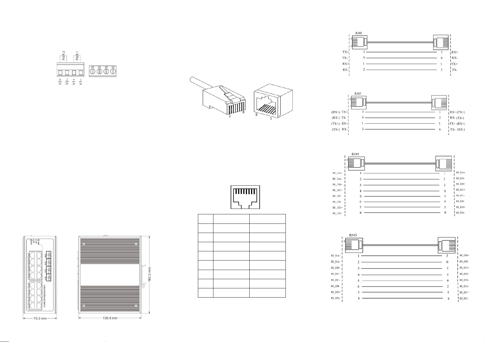
【Power supply input】
The switch top panel provided 4 bit power supply input terminal
block, support DC input. DC power supply input supported
redundancy function, provided PWR1 and PWR2 power input,
can use for single, and can connect 2 separately power supply
system, use 1 pair terminal block connect the device at the same
time. If one of the power systems broke, the device can work
un-interruptible. Built-in overcorrect protection, Reverse
connection protection. Voltage input range is 12 ~48VDC
(terminal block defined as: V1-、V1+、V2-、V2+).
Important notice:
1. Power ON operation: first of all, insert power cable’s terminal
block into device’s power port, then insert power supply plug into
power source
2. Power OFF operation: First off all, unpin power plug, then
strike the terminal block, please take care of operation sequence.
【Dimension】
【Communication connector】
10/100/1000BaseT(X) Ethernet port
The pinout of RJ45 port display as below, connect by UTP or STP.
The connect distance is no more than 100m. 1000Mbps is used
120Ω of UTP 5e; 100Mbps is used 120Ω of UTP 5; 10Mbps is
used 120Ω of UTP 3, 4, 5.
RJ 45 port support automatic MDI/MDI-X operation. That can
connect the PC, Server, Converter and HUB. Pin 1, 2, 3, 4, 5, 6, 7,
8 Corresponding connections in MDI. 1→3, 2→6, 3→1, 4→7,
5→8, 6→2, 7→4, 8→5, are used as cross wiring in the MDI-X
port of Converter and HUB. In MDI/MDI-X, 100/1000Base-TX
PIN defines is as follows:
PIN MDI MDI-X
1 BI_DA+/TX+ BI_DB+/RX+
2 BI_DA-/TX- BI_DB-/RX-
3 BI_DB+/RX+ BI_DA+/TX+
4 BI_DC+/—BI_DD+/—
5 BI_DC-/—BI_DD-/—
6 BI_DB-/RX- BI_DA-/TX-
7 BI_DD+/—BI_DC+/—
8 BI_DD-/—BI_DC-/—
Note:10Base-T/100Base-TX, “TX±”transmit data±, “RX±”receive data±,
“—”not use.
10/100Base-T(X) MDI (straight-through cable)
10/100Base-T(X) MDI-X (Cross over cable)
Gigabit MDI (straight-through cable)
Gigabit MDI-X (Cross over cable)
MDI/MDI-X auto connection makes switch easy to use for
customers without considering the type of network cable.
1 8
- 3 -
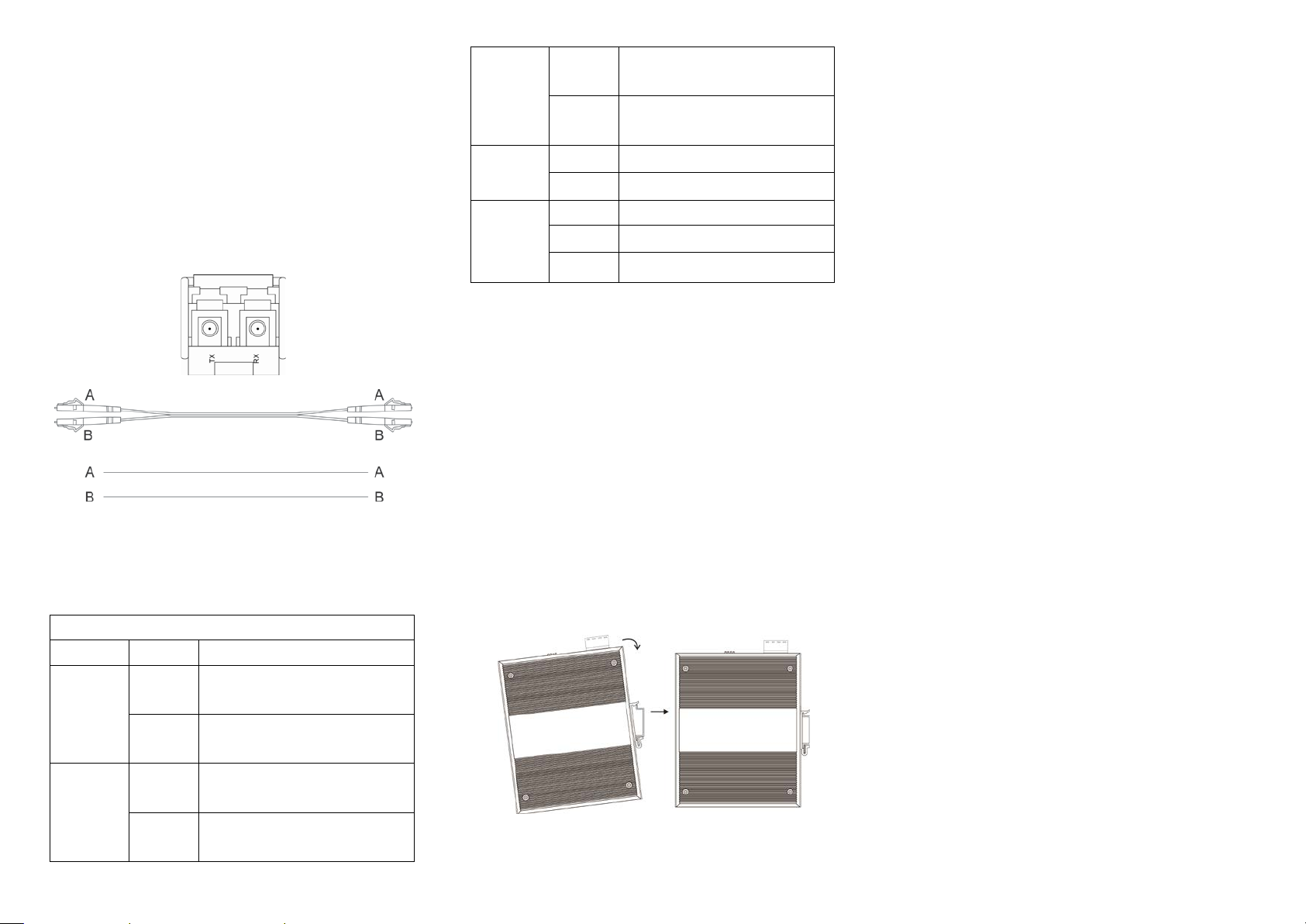
1000Base SFP fiber port(mini-GBIC)
1000Base SFP fiber port adopts gigabit mini-GBIC transmission,
can choice different SFP module according to different transfer
distance. Fiber interface must use for pair, TX port is transmit side,
must connect to RX (receive side). The fiber interface support loss
line indicator.
Suppose: If you make your own cable, we suggest labeling the
two sides of the same line with the same letter (A-to-A and
B-to-B, shown as below, or A1-to-A2 and B1-to-B2).
【LED Indicator】
LED indictor light on the front panel of product, the function of
each LED is described in the table as below.
System indication LED
LED State Description
P1
ON Power is being supplied to power
input PWR1
OFF Power is not being supplied to
power input PWR1
P2
ON Power is being supplied to power
input PWR2
OFF Power is not being supplied to
power input PWR2
Alarm
ON When the alarm is enabled, which
any one way power supply fault
OFF Power supply normal, the alarm is
disabled.
Run ON/OFF System is not running well
Blinking System is running well
Link/ACT
(G1~G20)
ON Port connection is active
Blinking Data transmitted
OFF Port connection is not active
【Installation】
Before installation, confirm that the work environment meet the
installation require, including the power needs and abundant
space. Whether it is close to the connection equipment and other
equipments are prepared or not.
1. Avoid in the sunshine, keep away from the heat fountainhead or
the area where in intense EMI.
2. Examine the cables and plugs that installation requirements.
3. Examine whether the cables be seemly or not (less than 100m)
according to reasonable scheme.
4. Power: support 12 ~ 48VDC power supply
5. Environment: working temperature: -40~75℃
Storage Temperature: -40~85℃
Relative humidity 5%~95%
DIN Rail Installation
In order to use in industrial environments expediently, the product
adopt 35mm DIN-Rail installation, the installation steps as below:
1.Examine the DIN-Rail attachment
2.Examine DIN Rail whether be firm and the position is
suitability or not.
3.Insert the top of the DIN-Rail into the slot just below the
stiff metal spring.
4.The DIN-Rail attachment unit will snap into place as shown
below.
Wiring Requirements
Cable laying need to meet the following requirements,
1. It is needed to check whether the type, quantity and
specification of cable match the requirement before cable
laying;
2. It is needed to check the cable is damaged or not, factory
records and quality assurance booklet before cable laying;
3. The required cable specification, quantity, direction and
laying position need to match construction requirements, and
cable length depends on actual position;
4. All the cable cannot have break-down and terminal in the
middle;
5. Cables should be straight in the hallways and turning;
6. Cable should be straight in the groove, and cannot beyond the
groove in case of holding back the inlet and outlet holes.
Cables should be banded and fixed when they are out of the
groove;
7. User cable should be separated from the power lines. Cables,
power lines and grounding lines cannot be overlapped and
mixed when they are in the same groove road. When cable is
too long, it cannot hold down other cable, but structure in the
middle of alignment rack;
8. Pigtail cannot be tied and swerved as less as possible.
Swerving radius cannot be too small (small swerving causes
terrible loss of link). Its banding should be moderate, not too
tight, and should be separated from other cables;

- 4 -
9. It should have corresponding simple signal at both sides of the
cable for maintaining.
【Specification】
Technology
Standard: IEEE802.3, IEEE802.3x, IEEE802.3u, IEEE802.3ab/z
Flow control: IEEE802.3x flow control, back press flow control
Exchange attribute
100M forward speed: 148810pps
1000M forward speed: 1488100pps
Transmit mode: store and forward
System exchange bandwidth: 56G
MAC address table: 10K
Memory: 12M
Interface
Gigabit RJ45 port: 10Base-T/100Base-TX/1000Base-TX auto
speed control, Half/full duplex and MDI/MDI-X auto detect
Gigabit SFP port: 1000Base-X, SFP slot
Console port: Retain
Alarm port: 2 bit terminal block
1 channel relay alarm output
Transfer distance
Twisted cable: 100M (standard CAT5/CAT5e cable)
Multi-mode: 1310nm, 2Km
Single-mode: 1310nm, 20/40Km
1550nm, 60/80/100/120Km
LED indicator
Run indicator: RUN
Interface indicator: Link (G1~G20)
Power supply indicator: P1, P2
Alarm indicator: ALM
Power supply
Input Voltage: 12~48VDC
Type of input: 4 bits terminal block
DC support reverse connection
DC support redundant power supply
Consumption
No-load consumption: 11.04W@48VDC
Full-load consumption: 12.88W@48VDC
Working environment
Working temperature: -40~75℃
Storage temperature: -40~85℃
Relative Humidity: 5%~95 %( no condensation)
Mechanical Structure
Shell: IP40 protect grade, metal shell
Installation: DIN-Rail mounts
Weight: 1080g
Size (W×H×D): 70mm×160mm×130mm
Industry Standard
EMI: FCC Part 15, CISPR (EN55022) class A
EMS: EN61000-4-2 (ESD), Level 3
EN61000-4-3 (RS), Level 3
EN61000-4-4 (EFT), Level 3
EN61000-4-5 (Surge), Level 3
EN61000-4-6 (CS), Level 3
EN61000-4-8, Level 5
Shock: IEC 60068-2-27
Free fall: IEC 60068-2-32
Vibration: IEC 60068-2-6
Certification
CE, FCC, RoHS, UL508 (Pending)
Warranty: 5 years
Table of contents
Other Shenzhen 3onedata Technology Network Router manuals


