Version:1027130315
1
Thesheetmetalisinsertedinto
thecorrespondinghole,a
vertical pressdown,toensure
thatthesheetmetalcloseto
base
Base
Sheetmetal
Base
sheetmetal
The screwdriver
inserted intothe
roundholefromthe
baseandpushthe
sheetmetalout.
InstuctionMannal of JTY-GD-S832 Point-type
Photoelectric SmokeDetector
Pleaseread through theseinstructionscarefullybeforeinstallationand use!
I. General
JTY-GD-S832 point-typephotoelectricsmokedetectorisaphotoelectric
smokedetector.As anon-polar two-wirepower inputisadoptedinthedetector,
itcandetect thesmokeand send outalarmsignalintimewhen firetaking
place.Asmicrocontrollerisadoptedinthedetector,itcanidentifythesmoke
concentration intellectually.Thedetector monitorssmokeconcentration inthe
workplaceinrealtime.Whilemonitoring,theredindicator blinksandthe
workingcurrent islow.Whentheworksitesmokeconcentrationhasexceeded
thepresetalarmthreshold,thedetectorisalarming and thered indicator
remainson,relayisdriven.Thedetector hasthefunctionofrelaycontact
output, alarmsignalisshownasthechangeofrelaycontact output, alarm
signalcanbekeptandthealarmcanonlyberesetbytheinstantpower
disconnection.Thedetectorhasan automaticcompensation functionagainst
dustaccumulation and canreducetheeffect ofduston thesensitivityofthe
detector.
Thesmokedetector isapplicableinplaceswherefiremightgenerate
volumesmoke,i.e.inindustrialandcivil buildingssuchasintherestaurant,
hotel,teaching building,officebuilding,computer cabinet, archivesandstack
room.
Fig.1
II. Features andtechnicalparameters
1.Executivestandard: GB4715-2005
2.Working voltage: DC12V/24V(allowance:9V~30V)
3.Working current:
During monitoring <1mA@DC12V<5mA@DC24V
Firealarm<30mA@DC12V<35mA@DC24V
4.Relayoutput: normallyopen (closed when alarm)
switchingcapacity 1A30VDC
5.Working indicator:
During monitoring, thered indicatorblinksonceabout per 6s.
Inalarmmode, theredindicatorremainson.
Infault mode, theredIndicator continuouslyblinkstwiceabout per6s.
6.Environment: Temperature: -10℃~+65℃
Relativehumidity:≤95%(40℃2℃non-condensing)
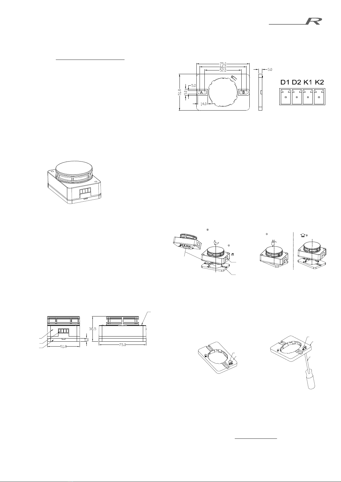
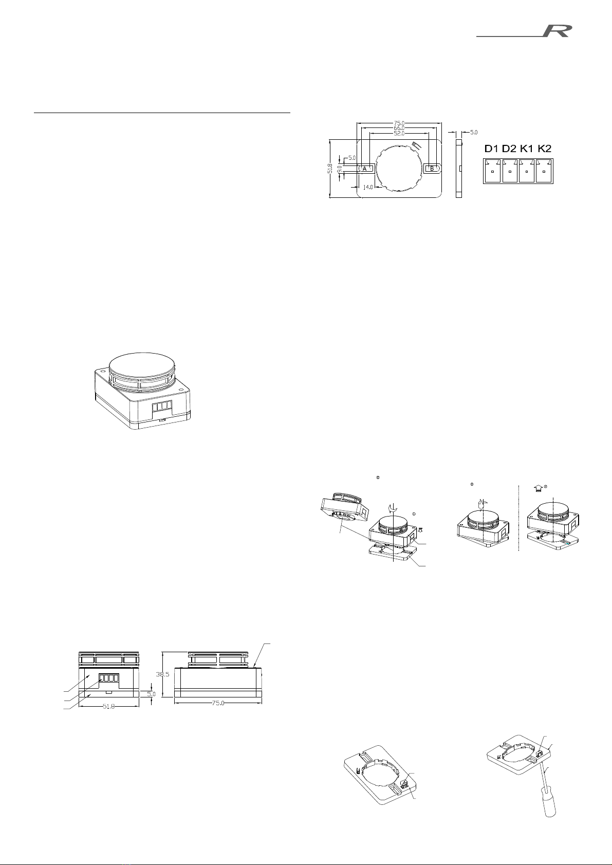
7.Exterior size: 75mm×51.8mm×38.5mm(withbase),asshowninfigure2,
Fig.2
8.Weight: about 80g
9.Standardpackingquantity: 100 PCS/CTN
10.Distancefromfloor: ≤12m
11.Areascovered:seetheprovisionsintheGB50116-98“Codefor Design
ofAutomatic FireAlarmSystem
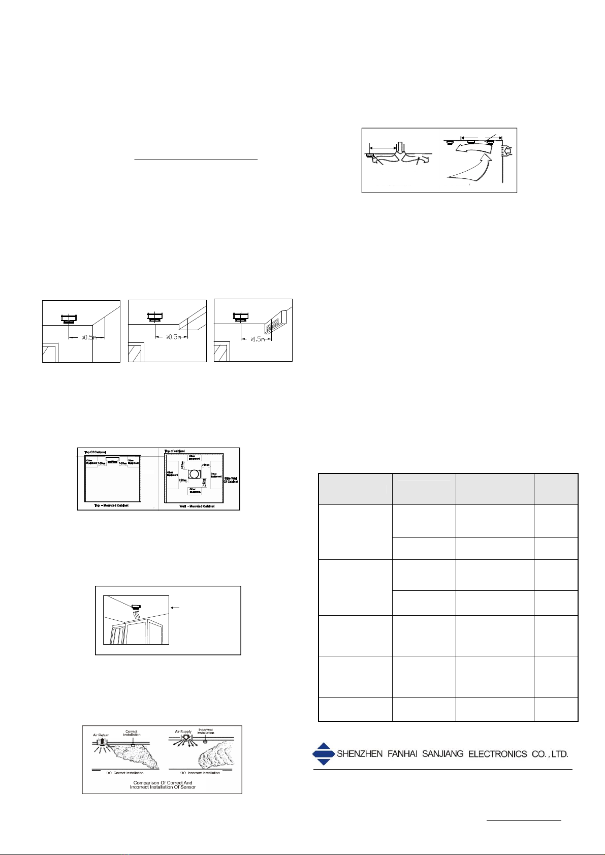
III. Installation and commissioning
Determinethelocation,mountingdistanceandnumbersformounting the
smokedetectorsintheprotection area inaccordancetotherelevant
stipulationsofGB50116-98.
Abaseshowninfigure3isrequiredfor mounting thesmokedetector;its
exterior sizeis75mm×51.8mm×5mm(L×W×H),thesizeofthefixing holeis
5mm×10mmand thedistancebetween theholesis52mm~66mm.
Thesmokedetectorconnectswithpower and other devicevia4PIN
PluggableTerminalBlock.AsShowninfigure4,D1 &D2 pinsarethepower
input terminals; K1& K2pinsaretheoutput terminalsoftherelay.
Fig.3Fig.4
Detailsoftheinstallation andcommissioning areasfollowing:
1.Installed basecanbeusedasfollows:
1)Preparetheshop drawing and fixtheauxiliarybaseontothe
defined location withtwoM4boltsinstalledthroughthetwofixing
holes(A、B showninfigure 3).
2)According totheshop drawing, useadrill toboretwo Φ6mm holes
ontodefinedlocation,then puttwoexpandableplasticstoppers into
theholesseparately, fixtheauxiliarybaseontothedefinedlocation
withtwoST3.5×20mm tappingscrewsinstalledthroughthetwo
fixing holes(A& B showninfigure3);
3)Magnet install intodesignated A, B fixedholeasshowninfigure3,
afterthebaseand thedetectorassembly,adsorbed detector onthe
metalcabinetorrackthrough themagnet, thisinstallationcouldbe
selected.
2.Disconnect thepower,connect all basescorrectlyaspertheshop
drawing,andthenconnect thecontrollerstothecorrespondinginput
ports.
3.Makesurethatall smokedetectorstypescorrespondwiththeones
notedintheshop drawing.
4.Tobeinstalledand disassembledthesmokedetector,asshowninfigure
5and figure6.
Fig.5Fig.6
5.Don’tpower on thecontrolleruntil all smokedetectorshavebeen
mounted correctly;toconfirmcorrect, connect detector powersupply.
First, thered indicator blinks once,and then enterthenormalstateto
monitoraboutevery6secondsblinksonce,indicatingthatdetectors
havebegun working;
6.Alarmtestofthedetector isperformedbyspecialtoolor puffing smoke
directly.Thered indicator remainsonafterthedetectoralarms.After
testing reset thedetector tomonitoring state.
7.After thebaseandthedetector assembly, Internaltermination
resistor(47KΩ) will beconnectedbetweenthe outputterminalsofthe
relay(K1,K2) throughthesheetmetalon thebase.Installation and
removalofthesheet metal, asshowninfigure7andfigure8.
Fig. 7Fig. 8
Turnthesensor
anticlockwise tothe
arrowed in the top view
Pullupthesensor
fromthebase
【The appearancehas
been applied for patents,
all rights reserved.】
Base
Smoke Sensor
Push down the
smoke sensor make
it align to the base
Turn the smoke
sensor clockwise in
thetop view,when
its bottom downto
the base,continue
turn it to arrowed
Bottom
Indicator
Sensor
Wiring port
Base