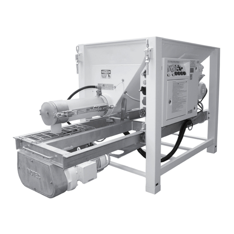
Shibuya Hoppmann Cap Star FCCPSTLDSA Instruction Manual

➟
Please copy this
information from the
CapStar
serial plate.
Cap Feeder
ANSI/Metric Installation
& Maintenance Manual
Refer all servicing to
qualified personnel.
This manual is intended
for use by qualified
mechanics and electricians
who install or service the
CapStar Cap Feeder
Inventory Number (Check One):
❑FCCPSTLDSA ❑FCCPSTRDSA
❑FCCPSTLASM ❑FCCPSTRASM
Cap Star
First Edition, Publication Version, All Rights Reserved
Copyright © 2002 by Hoppmann Corporation.
15395 John Marshall Highway
Haymarket, VA 20169
Phone: (703) 753-8888
Toll Free: (800) 368-3582
Fax: (703) 753-7485
http://www.hoppmann.com
Inventory/Serial Number:

CapStar Feeder Installation/Maintenance Manual
2
About this Manual
Assumptions Hoppmann Corporation assumes that all procedures contained in
thismanualwillbeperformedbyaqualifiedmechanicorelectrician
whomustinstall or servicetheCapStar Cap Feeder.Allprocedures
in this manual should be performed by qualified personnel or
under their direction.
Models Covered This manual covers four models. For spare parts purposes and/or
troubleshooting, locate the inventory number on the serial plate of
the equipment prior to contacting Hoppmann.
Inventory No.
FCCPSTLDSA............... Left Hand, SS, 90 Volt DC Motor
FCCPSTLASM .............. Left Hand, SS, 50 Hz AC Motor
FCCPSTRDSA .............. Right Hand, SS, 90 Volt DC Motor
FCCPSTRASM.............. Right Hand, SS, 50 Hz AC Motor
Caution Symbols Caution symbols and messages in this manual call attention to
and Messages hazardous voltages, moving parts and other hazardous conditions.
The exclamation point caution symbol denotes possible personal
injury and/or damage to the equipment.
Thelightningbolt caution symboldenotespossible personal injury
and/or damage to the equipment from electrical hazards.
Before You Start
Tools You Will Need The CapStar Cap Feeders are offered in both ANSI and metric
versions. For maximum compatibility, ANSI units are classified as
“soft ANSI” construction, meaning that metric threads and hard-
ware are used throughout. Both metric and ANSI units require
metric tools for repair or adjustment.
▲
Quick Start
Equipment Improvements & Hoppmann Corporation continually improves its products and reserves the right to change or
Document Revisions Notice discontinue specifications and designs shown in this manual without notice and without
incurring obligation. Hoppmann Corporation has made every effort to verify the information
contained in this manual, but reserves the right to correct any error at the time of the manual’s next
revision. This manual is subject to change without notice. 7/22/02

3
Quick Start 2About this Manual
2Before You Start
CapStar Description 5The CapStar Cap Feeder: An Overview
& Specifications 6Cap Feeding Process
Figures/Tables:
5Figure 1-1. CapStar Cap Feeder
7Figure 1-2. CapStar Head
8Figure 1-3. CapStar Tooling
9Table 1-1. CapStar Feeder Specifications
10 Figure 1-4. CapStar Feeder Specifications
Safety Precautions 11 Warnings
Installation & Startup 13 If the CapStar Cap Feeder is Already Set Up
13 Unpacking and Inspection
14 Physical Setup
15 Setup
15 Initial Settings
17 Making Tooling Adjustments
19 Motor/Speed Reducer/Idler Assembly
22 Electrical Wiring
Figures:
14 Figure 3-1. Adjusting the Height
17 Figure 3-2. Secondary Hopper Location
18 Figure 3-3. CapStar Tooling
19 Figure 3-4 Height Adjustment
19 Figure 3-5. CapStar Speed Reducer
20 Figure 3-6. DC ANSI Suggested Wiring Diagram
21 Figure 3-7. AC Metric Suggested Wiring Diagram
23 Figure 3-8. CapStar Wiring Schematic
24 Figure 3-9. CapStar Wiring Schematic
ChapterPage
Table of Contents
2
3
1

CapStar Feeder Installation/Maintenance Manual
4
Repair and 25 Preventive Maintenance
Maintenance 25 General Maintenance
25 General Cleaning
25 Conveyor Belt Installation and Replacement
28 Elevator Belt Installation and Replacement
Figures:
26 Figure 4-1. Conveyor Belt Replacement - Exploded View
Replacement Parts 29 Notice to Hoppmann Corporation Customers
31 Warranty
32 Scheduled Preventive Maintenance Log
Figures:
29 Figure 5-1. Serial Plate Layouts
5
ChapterPage
Table of Contents Continued
4

5
1
Description & Specifications
The CapStar Cap Feeder: An Overview
The CapStar Cap Feeder will integrate into an in-line product
handling system, or stand-alone and orient caps (see Figure 1-1).
Function The CapStar Cap Feeder is designed to dispense a wide variety of
cap sizes and shapes, at a cap delivery speed of 40 to 600 parts per
minute. Changeover from one cap style to another takes less than
five minutes and is straightforward. No special training is needed.
Figure 1-1. CapStar Cap Feeder (Right Hand Unit)
Polypropylene
Elevator Belt
Electrical
Cabinet
Primary
Hopper
Singulation
Wiper Horizontal
Conveyor Feed
Belt
Hand Crank
Leveling
Feet
Casters
Pulley
Take Up
Secondary
Hopper
Air Prox
Positive Pressure
Sensor
Return Chute

CapStar Feeder Installation/Maintenance Manual
6
Standard Equipment Standard design features of the CapStar Feeder are:
Features ➤Simple design and ease of use
➤White polypropylene cleated belt
➤FDA approved white urethane impregnated continuous belt
➤No tools required to changeover to another cap style
➤Small footprint
➤Easy retrofit to existing cappers
➤Right-hand and left-hand cap feeders available
Cap Feeding Process
The following description explains the cap feeding process as the
capgoesthroughtheCapStarCapfeederstartingwithadescription
of the unit and then how the CapStar works. Understanding the
process will help the operator or technician in setting up the
machine as well as servicing and troubleshooting the equipment.
Positioning,initial setup and poweringthecapfeederwithelectrical
and pneumatic power will be described in Chapter 3.
The CapStar Cap Feeder is bolted onto an adjustable center stand
using two support arms. The support arms ride on friction guides
that are used to raise and lower the unit when the hand crank is
turned. The vertical movement combined with the caster wheels
allow the unit to be positioned exactly where it is needed.
Caps are loaded into the primary hopper bin (see Figure 1-1
previous page). The elevator uses a continuous belt to transport a
steady supply of caps from the hopper, up and over the center
stand where they are then loaded into a secondary hopper (see
Figure 1-2). The secondary hopper is a settling area to prevent caps
from bouncing away from the horizontal feeder belt.
The caps settle onto the horizontal FDA approved white urethane
feed belt. The belt carries the caps past the singulation wiper and
the height qualifier (see Figure 1-2 and 1-3). These two tooling
features allow only single file caps (one cap diameter at a time) to
pass by and continue down the conveyor. Caps which are

7
misoriented or do not meet the requirements set by the wiper and
qualifier are deflected down the return chute and recirculated.
The single row of caps pass by a positive pressure sensor (the air
prox - see Figure 1-3). The positive pressure sensor continually
blows a low volume, low pressure stream of air at the caps.
As each cap passes the sensor, the air stream blowing down creates
a back pressure. The sensor reads the back pressure, and, if the cap
is misoriented, triggers a reject airjet to blow the cap down the
return chute. Correctly oriented caps are allowed to pass the airjet
and positive pressure sensor, and continue down the conveyor.
Chapter 1 Description and Specifications
Figure 1-2. CapStar Head
Polypropylene
Elevator Belt
Electrical
Cabinet
Singulation
Wiper
Horizontal
Conveyor Feed
Belt
Secondary
Hopper
Return
Chute
Air Prox
Positive Pressure
Sensor
Height
Qualifier

CapStar Feeder Installation/Maintenance Manual
8
See Chapter 3, Installation & Start-up, for the setup details.
Figure 1-3. CapStar Tooling
Height
Qualifier
Air Prox
Conveyor
Tooling
Support
Wall
Orientation
Qualifier
Wiper
Singulation
Wiper

9
Product Specifications ANSI Metric
Inventory No. FCCPSTLDSA FCCPSTLASM
FCCPSTRDSA FCCPSTRASM
Electrical Specifications
Elevator Motor Size 1/4HP 186 Watts
Conveyor/Feed Belt Motor Size 1/5HP 150 Watts
Supply Voltage Refer to Chapter 3 Wiring Diagram
Drive Motor Voltage Refer to Chapter 3 Wiring Diagram
Power Usage Refer to Chapter 3 Wiring Diagram
Weight ≈1000 lbs ≈453.6 kg
Hopper Capacity 4 ft3115 liters
Dimensional Specifications
A. Overall Height 65"- 81"1655 mm - 2060 m
B. Load Height 35"- 51 "908 mm - 1314 mm
C. Discharge Height 46"- 62"1174 mm - 1580 mm
D. Overall Length 60"1536 mm
E. Overall Width 54"1371 mm
F. Belt Width (Horizontal) 6"152 mm
G. Interfaced Conveyor Clearance 7"178 mm
Performance Specifications
Elevator Max Speed 37 feet/min
Conveyor Max Speed 43 feet/min
Table 1-1. CapStar Cap Feeder Specifications
Your direct supplier may have changed some of these specifications
during tooling to better match your application’s requirements.
CapStar Cap Feeder Specifications
Chapter 1 Description and Specifications

CapStar Feeder Installation/Maintenance Manual
10
Figure 1-4 CapStar Cap Feeder Specifications
Your direct supplier may have changed some of these specifications
during tooling to better match your application’s requirements.
CapStar Cap Feeder Specifications
E
F
F
A
BC
L
C
G

11
Warnings
Turn Off Power! Before servicing, make sure you have turned off
compressed air and electrical power in a way which prevents
accidental reactivation. Padlock and clearly tag the appropriate
electrical and pneumatic disconnects. Lockout/tagout procedures
are covered in United States Code of Federal Regulation (CFR)
Title 29 Part 1910.147, “The Control of Hazardous Energy.”
Dress Appropriately! Reduce the risk of injury from moving parts
by securing loose sleeves and other clothing. Do not wear loose
jewelry or neckties near the equipment. Wear safety glasses or
otherprotectiveeye wear whenservicingor operating theCapStar.
Never place hands or tools in the equipment when it is operating.
Avoid Pinch Points! Exposed pinch points include the elevating
belt at the bottom of the hopper and at the intersection of the
horizontal belt. At the horizontal belt where the cap sorter guides
deflect caps.
Avoid Dangerous Conditions! This machine is not designed to
workin explosive or wet environments. Dryconditions arecritical
for a long life. Normal operation inherently causes static electricity
tobuildup;avoid explosive or potentiallyexplosiveenvironments.
Safety Precautions
2

13
3
Installation & Startup
If the CapStar is Already Set Up
IfyoubuyaHoppmann CapStar Cap FeederaspartofaHoppmann
feeder system, then your direct supplier will have performed all
the procedures in this chapter. You will still need to:
▲
Position your CapStar Cap Feeder. Follow the equipment
layout drawing provided by your direct supplier.
▲
Connect Electrical Wiring. Follow as-built electrical diagrams
provided by your direct supplier.
▲
Make Pneumatic Connections. If your CapStar has a hopper
agitator,yourdirect supplier will provideyousetup specifications.
▲
Install and Test the Rest of the System. Installation is complete.
If the Hoppmann CapStar Cap Feeder is drop-shipped to your location,
follow the procedures in this chapter to finish setting up the feeder.
Unpacking and Inspection
Step1—InspectandUnpack the Crate. Removepackingmaterials
from sensors, tooling and moving parts. Make a visual check to be
sure parts have not come loose during shipping. If you find any
concealed damage, call the shipping carrier and your direct sup-
plier immediately. Do not attempt to fix the problem yourself
unless told to do so by your direct supplier.
Step2—Record Serial Number of the CapStar.If you have not
already done so, record the CapStar’s inventory/serial number on
the front of this manual. This information is necessary when ordering
replacement parts or service.
The CapStar Feeder is secured to the floor of the crate and the
weight of the unit is on four leveling footpads. When the unit is
lifted from the floor of the crate, the leveling feet can be raised to
allow the casters to rest on the shop floor. Once the unit has been
positioned, the casters can be locked or the footpads can be
lowered for a stable footing. The leveling feet can be used to level
the unit and they have anchor holes to allow anchoring.

CapStar Feeder Installation/Maintenance Manual
14
Physical Setup
Step 1—Position the CapStar Cap Feeder. Place the feeder as
shown on the equipment layout drawing provided by your direct
supplier.
Step2—Position the CapStar Cap Feeder.The CapStar can be
moved around on it’s casters into position. Press the tab on each
wheel to lock the wheel and keep it from turning. The casters are
locked by stepping down on the locking tabs. When the wheel is
free,step onor press down on theouter edgeof thelocking tab. The
brake engages the wheel and the wheel brake tab protrudes above
the larger locking tab.
To release the brake, step on the small wheel brake tab or lift up on
the larger locking tab.
Lower the feet until the weight is transferred to the feet and engage
the locknuts.
A level should be placed on the horizontal continuous belt and the
unit should be leveled.
The unit can be raised or lowered into position
by turning the hand crank that is located at the
bottom of the center post. The hand crank can
be turned with little effort in either direction
(refer to Figure 3-1).
➮To raise the unit:
- turn the hand crank clockwise.
➮To lower the unit:
- turn the hand crank counterclockwise.
Figure 3-1. Adjusting the Height
Hand
Crank
Pulley
Take Up
Caster

15
Setup
The CapStar Cap Feeder must be setup to run the particular style
of cap. As a point of reference, the hand crank and electrical box
is on the front of the machine. The hopper is the back. The hand
crank is at the bottom and electrical box is at the top of the unit.
Left and right hand CapStar units are distinguished by standing
at the front of the unit and looking back to the hopper. The
pneumatic regulator is located on the support arm.
Initial Settings
To setup for the initial run or to change to another size or style
of cap, block the end of the qualifier with a recirculating plate.
This will allow a quantity of caps to be run without introducing
them into the system.
Step 1—Adjust the Height. Adjust the height qualifier wiper by
loosening the knob and setting the height 1/8"to 1/4" above the cap.
Step 2—Set the Angle. Set the angle of the singulation wiper by
loosing the hand knob and pivoting the wiper so that only one cap
(by diameter) can pass the wiper.
The CapStar Cap Feeder is now setup to send a line of caps to the
orientation qualifier.
Step 3—Orientation. The orientation qualifier is set to allow one
cap (one cap diameter form the edge of the belt to the face of the
singulation wiper) to pass along the conveyor. Any side-by-side
caps will be rejected and pushed by a reject airjet down the return
chute for recirculation. Additionally, the orientation qualifier has
a height adjustment. The adjustment is based on height of one cap
with an allowance of approximately 1/8". To adjust the height
loosen the knobs holding the plate in place, and raise/lower the
plate so that there is a gap of 1/8" between the qualifier and a cap.
Retighten the hand knobs.
Chapter 3 Installation & Startup
Continued
▲

CapStar Feeder Installation/Maintenance Manual
16
Step 4—Fill Hopper. Fill the hopper with a quantity of product to
be fed.
Before connecting air, turn the pneumatic regulator
counterclockwisetopreventthesystemfrombecoming pressurized
when the shop air is attached.
Step5—Connect Power and Air.Connect the CapStar to power and
compressed air to the regulator and set the pressure to and initial
setting of 40 - 50 psi (see Figure 3-1).
The orientation sensor bleeds air continuously. This is normal.
Since bleeding air makes noise, feel around the air lines and the air
line connectors for leaks.
Connect the electrical power by plugging in the end of the power
cord into a properly grounded 115 VAC receptacle. The plug end
should prevent connecting to the wrong voltage.
Turn the main power switch on. Rotate the switch clockwise to
energize. The EMERGENCY STOP switch should be pulled out
and illuminated. When the EMERGENCY STOP switch is pushed
in the electrical power is cut off and the light is off.
If the motors do not start to run, turn the speed controls up until
the elevator belt starts to lift caps out of the hopper. It is
recommended to start at a slow belt speed through the setup.
Watch the caps as they are dropped onto the horizontal feed belt.
Watch the caps pass by the height qualifier. Stacked caps should
be pushed aside and sent down the return chute.
A single line of caps should be passing under the orientation
qualifier. Cavity up caps should pass through and cavity down
caps should be blown down the return chute.
Once the setup is complete, press the stop button.
Remove the recirculating plate from the downstream path of the
caps.

17
Secondary
Hopper
Horizontal
Conveyor
Belt
Electrical
Control
Box
Cleated
Elevator
Belt
Chapter 3 Installation & Startup
The CapStar Cap Feeder is now ready to feed cavity up caps into
the system.
The CapStar Cap Feeder is equipped with a cleanout door in the
base of the hopper, and can be used to quickly empty product for
changeover.
Making Tooling Adjustments
Product which is carried from the primary hopper by the elevator,
belt, is metered into a secondary hopper (see Figure 3-2). The
secondary hopper assists with settling the parts before they enter
the tooling area and horizontal conveyor.
Step 1—Adjust the Speed. The speed at which the elevator is run
shouldbesetso that the productinthesecondaryhoppermaintains
a consistent level. Parts leave the secondary hopper at the same
rate or faster than they enter ensuring the proper fill level of the
secondary hopper.
Figure 3-2. Secondary Hopper Location - CapStar Topview

CapStar Feeder Installation/Maintenance Manual
18
Height
Qualifier
Air Prox
Conveyor
Tooling
Support
Wall
Orientation
Qualifier
Wiper
Singulation
Wiper
Product metered from the secondary hopper loads onto the
conveyorand into the tooling sectionof theCapStar for singulation
and qualification.
Step2—Adjust Height Qualifier. The
height qualifier plate is adjusted to
allow only one part thickness to pass
underneath it. This wiper has 1.88” of
vertical adjustment allowance. The
height qualifier plate is attached to the
deflector plate (see Figure 3-3).
Step 3—Adjust Singulation Wiper.
The singulation wiper is a hinged wall
which can be adjusted to different
angles. The height qualifier wiper and
the singulation wiper work together
(see Figure 3-3). They are adjusted to
allow only one single level of parts to
pass in a single file line.
Step 4—Adjust Air Proximity Vertical and Horizontal Position.
When caps enter the second stage of tooling - or the orientation
qualifier area, the air prox will qualify the part to a cavity up
position. The air prox is attached to the tooling support wall. To
adjust the wall loosen the hand knobs on the back side of the wall,
and move it up or down, in or out, based on the cap size being run.
Place a cap between two flanges (see Figure 3-4 following page),
leaving an 1/8" gap between the top of the cap and the top flange,
and retighten the hand knobs. With regards to the reject airjet,
place a cap beneath the airjet nozzle and adjust the nozzle so that
the vertical tip is no greater than .100” above the surface of the cap.
Adjust the airjet horizontally so that the airflow hits the surface of
the cap as close to the centerline as possible.
Figure 3-3. CapStar Tooling

19
Chapter 3 Installation & Startup
Step 5—Set Air Proximity. The air pressure at the air proximity is
to be set just high enough to trigger the airjet which will fire the
airjet and reject a cavity down part.
Note: All qualified product is discharged at
the end of the conveyor in a single stream
andcontinuestothecustomersdownstream
equipment. Any rejected product, enters the
return chute and is reintroduced into the
system for recirculation.
Motor/Speed Reducer/Idler Assembly
Speed Reducer—No Lubrication Required. The speed reducer
used in the CapStar is lubricated for life with synthetic lubricant
and requires no regular maintenance (see Figure 3-5).
Figure 3-5. CapStar Speed Reducer
Reducer Idler
Assembly
Motor
Motor Mount
Figure 3-4. Height Adjustment
Height
Adjustment
Knobs
Height
Qualifier
Place
Caps
between
Flanges

CapStar Feeder Installation/Maintenance Manual
20
Specifications
CapStar Motor Wiring Diagram - DC ANSI
Elevator Motor
Conveyor Belt Motor
Figure 3-6. DC ANSI Suggested Wiring Diagram
DC Motor Speed
Controller
Line Input
Plug-In Horsepower
Resistor (R21)
KBIC-118
115 VAC
0.05 Ohm 1/4HP
0.10 Ohm 1/5HP
1/4HP Hoppmann Part Number MOTRPM25HP
1/5HP Hoppmann Part Number MOTRP.20HP
1
2
3
4
P2
L2
L1
F -
ACCEL
DECEL
MAXMIN P1
P3
A -
A + F+
R21
IR CL
AC LINE IN
5K Main Speed Potentiometer
P3 - Violet
P2 - Orange
P1 - White
ARMATURE
D.C. MOTOR
CW
RED
BLK
KBIC - 118
&
KBIC - 218
1
3
2
4
Notes:
▲
Do not use this diagram if your CapStar has an AC motor or a different motor speed controller
than shown. Follow the suggested wiring drawing provided by your direct supplier.
▲
Motor Controller Start-Stop Options:
Option 1: Open P3 circuit of speed pot with a pilot duty switch circuit for stop.
Option 2: Interrupt line voltage.
▲
To reverse motor rotation interchange leads A+ and A-.
▲
If equipped with shunt motor then F+ and F- are connected.
▲
For additional info: See “KBIC® Solid State DC Motor Speed Control Installation and Operating
Instructions” in U.S.A. from KB Electronics, Inc., Brooklyn, NY 11207. Plug-In Horsepower Resistor
is a registered trademark of KB Electronics Inc. for its electronic motor control circuit apparatus.

21
Specifications
CapStar Motor Wiring Diagram - AC Metric Drive
Elevator Motor
Conveyor Belt Motor
Figure 3-7. AC Metric Suggested Wiring Diagram
Mounting IEC 63A Face Mounting
186 Watts; Hoppmann Part Number MOTORMAC025
150 Watts; Hoppmann Part Number MOTRM.20HP
T6 T4 T5
T1 T2 T3
L1 L2 L3
T6 T4 T5
T1 T2 T3
L1 L2 L3
HIGH VOLTAGELOW VOLTAGE
220V - 50 HZ 380V - 50 HZ
FRAME
SINGLE
SPEED
DFT 71
DFT 8fl
Protection Level IP54 Protection Level
Chapter 3 Installation & Startup
This manual suits for next models
3
Table of contents
Popular Industrial Equipment manuals by other brands
Flexco
Flexco Clipper Pro 200 Operation manual
ABB
ABB HT572894 Operation manual
TrojanLabel
TrojanLabel T3-OPX user guide

Hussmann
Hussmann austral DH13-1 Series installation manual

Siemens
Siemens Power M12 Plug PRO Compact operating instructions
INOXPA
INOXPA CPG Series Installation, service & maintenance instruction
